Licensing Requirements
For a complete explanation of Cisco NX-OS licensing recommendations and how to obtain and apply licenses, see the Cisco NX-OS Licensing Guide.
The documentation set for this product strives to use bias-free language. For the purposes of this documentation set, bias-free is defined as language that does not imply discrimination based on age, disability, gender, racial identity, ethnic identity, sexual orientation, socioeconomic status, and intersectionality. Exceptions may be present in the documentation due to language that is hardcoded in the user interfaces of the product software, language used based on RFP documentation, or language that is used by a referenced third-party product. Learn more about how Cisco is using Inclusive Language.
This chapter describes the multicast features of Cisco NX-OS.
For a complete explanation of Cisco NX-OS licensing recommendations and how to obtain and apply licenses, see the Cisco NX-OS Licensing Guide.
IP multicast is a method of forwarding the same set of IP packets to a number of hosts within a network. You can use multicast in both IPv4 and IPv6 networks to provide efficient delivery of data to multiple destinations.
 Note |
Beginning with Cisco NX-OS Release 5.2(1) for the Nexus 7000 Series devices, you can configure Protocol-Independent Multicast v4 (PIMv4) to run over generic routing encapsulation (GRE) tunnels including outgoing interfaces (OIF). In prior Cisco NX-OS releases, tunnel interfaces do not support PIM. |
Note |
Beginning with Cisco NX-OS Release 7.3(0)DX(1), multicast generic routing encapsulation (mGRE) tunnels is supported on M3 Series modules. |
Multicast involves both a method of delivery and discovery of senders and receivers of multicast data, which is transmitted on IP multicast addresses called groups. A multicast address that includes a group and source IP address is often referred to as a channel. The Internet Assigned Number Authority (IANA) has assigned 224.0.0.0 through 239.255.255.255 as IPv4 multicast addresses. For more information, see http://www.iana.org/assignments/multicast-addresses.
IPv6 multicast addresses begin with 0xFF. The IPv6 addressing architecture is defined by RFC 4291. For more information about the IANA reserved addresses, see http://www.iana.org/assignments/ipv6-multicast-addresses.
Note |
For a complete list of RFCs related to multicast, see IETF RFCs for IP Multicast. |
The routers in the network listen for receivers to advertise their interest in receiving multicast data from selected groups. The routers then replicate and forward the data from sources to the interested receivers. Multicast data for a group is transmitted only to those LAN segments with receivers that requested it.
This figure shows one source transmitting multicast data that is delivered to two receivers. In the figure, because the center host is on a LAN segment where no receiver requested multicast data, no data is delivered to that receiver.

A multicast distribution tree represents the path that multicast data takes between the routers that connect sources and receivers. The multicast software builds different types of trees to support different multicast methods.
A source tree represents the shortest path that the multicast traffic takes through the network from the sources that transmit to a particular multicast group to receivers that requested traffic from that same group. Because of the shortest path characteristic of a source tree, this tree is often referred to as a shortest path tree (SPT). This figure shows a source tree for group 224.1.1.1 that begins at host A and connects to hosts B and C.
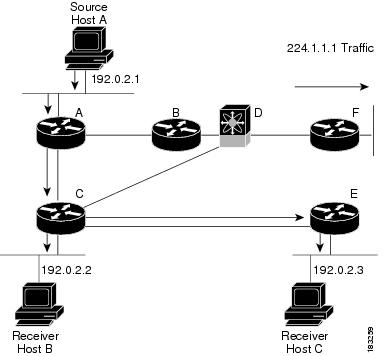
The notation (S, G) represents the multicast traffic from source S on group G. The SPT in this figure is written (192.0.2.1, 224.1.1.1). Multiple sources can be transmitting on the same group.
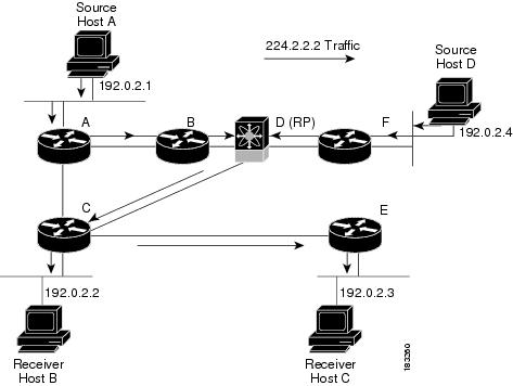
A shared tree represents the shared distribution path that the multicast traffic takes through the network from a shared root or rendezvous point (RP) to each receiver. (The RP creates an SPT to each source.) A shared tree is also called an RP tree (RPT). The figure below shows a shared tree for group 224.1.1.1 with the RP at router D. Source hosts A and D send their data to router D, the RP, which then forwards the traffic to receiver hosts B and C.
The notation (*, G) represents the multicast traffic from any source on group G. The shared tree in this figure is written (*, 224.2.2.2).
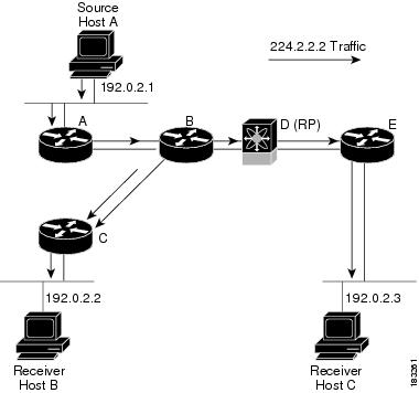
A bidirectional shared tree represents the shared distribution path that the multicast traffic takes through the network from a shared root, or rendezvous point (RP), to each receiver. Multicast data is forwarded to receivers encountered on the way to the RP. The advantage of the bidirectional shared tree is shown in the figure below. Multicast traffic flows directly from host A to host B through routers B and C. In a shared tree, the data from source host A is first sent to the RP (router D) and then forwarded to router B for delivery to host B.
The notation (*, G) represents the multicast traffic from any source on group G. The bidirectional tree in the figure below is written (*, 224.2.2.2).
Because multicast traffic is destined for an arbitrary group of hosts, the router uses reverse path forwarding (RPF) to route data to active receivers for the group. When receivers join a group, a path is formed either toward the source (SSM mode) or the RP (ASM or Bidir mode). The path from a source to a receiver flows in the reverse direction from the path that was created when the receiver joined the group.
For each incoming multicast packet, the router performs an RPF check. If the packet arrives on the interface leading to the source, the packet is forwarded out each interface in the outgoing interface (OIF) list for the group. Otherwise, the router drops the packet.
Note |
In Bidir mode, if a packet arrives on a non-RPF interface, and the interface was elected as the designated forwarder (DF), then the packet is also forwarded in the upstream direction toward the RP. |
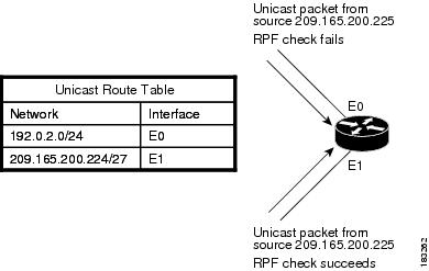
The figure below shows an example of RPF checks on packets coming in from different interfaces. The packet that arrives on E0 fails the RPF check because the unicast route table lists the source of the network on interface E1. The packet that arrives on E1 passes the RPF check because the unicast route table lists the source of that network on interface E1.
Cisco NX-OS supports multicasting with Protocol Independent Multicast (PIM) sparse mode. PIM is IP routing protocol independent and can leverage whichever unicast routing protocols are used to populate the unicast routing table. In PIM sparse mode, multicast traffic is sent only to locations of the network that specifically request it. PIM dense mode is not supported by Cisco NX-OS.
Note |
In this publication, the term “PIM” is used for PIM sparse mode version 2. |
To access multicast commands, you must enable the PIM or PIM6 feature. Multicast is enabled only after you enable PIM or PIM6 on an interface of each router in a domain. You configure PIM for an IPv4 network and PIM6 for an IPv6 network. By default, IGMP and MLD are running on the system.
PIM, which is used between multicast-capable routers, advertises group membership across a routing domain by constructing multicast distribution trees. PIM builds shared distribution trees on which packets from multiple sources are forwarded, as well as source distribution trees, on which packets from a single source are forwarded.
The distribution trees change automatically to reflect the topology changes due to link or router failures. PIM dynamically tracks both multicast-capable sources and receivers, although the source state is not created in Bidir mode.
The router uses the unicast routing table and RPF routes for multicast to create multicast routing information. In Bidir mode, additional routing information is created.
Note |
In this publication, “PIM for IPv4” and “PIM6 for IPv6” refer to the Cisco NX-OS implementation of PIM sparse mode. A PIM domain can include both an IPv4 and an IPv6 network. |
The figure below shows two PIM domains in an IPv4 network.
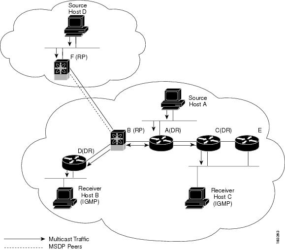
The lines with arrows show the path of the multicast data through the network. The multicast data originates from the sources at hosts A and D.
The dashed line connects routers B and F, which are Multicast Source Discovery Protocol (MSDP) peers. MSDP supports the discovery of multicast sources in other PIM domains.
Hosts B and C receive multicast data by using the Internet Group Management Protocol (IGMP) to advertise requests to join a multicast group.
Routers A, C, and D are designated routers (DRs). When more than one router is connected to a LAN segment, such as C and E, the PIM software chooses one router to be the DR so that only one router is responsible for putting multicast data on the segment
Router B is the rendezvous point (RP) for one PIM domain and router F is the RP for the other PIM domain. The RP provides a common point for connecting sources and receivers within a PIM domain.
This figure shows two PIM6 domains in an IPv6 network. In an IPv6 network, receivers that want to receive multicast data use the Multicast Listener Discovery (MLD) protocol to advertise requests to join a multicast group. MSDP, which allows for discovery of multicast sources in other PIM domains, is not supported for IPv6. You can configure IPv6 peers and use Source-Specific Multicast (SSM) and Multiprotocol BGP (MBGP) to forward multicast data between PIM6 domains.

PIM supports three multicast modes for connecting sources and receivers:
Any source multicast (ASM)
Source-specific multicast (SSM)
Bidirectional shared trees (Bidir)
Cisco NX-OS supports a combination of these modes for different ranges of multicast groups. You can also define RPF routes for multicast.
Any Source Multicast (ASM) is a PIM tree building mode that uses shared trees to discover new sources and receivers as well as source trees to form shortest paths from receivers to sources. The shared tree uses a network node as the root, called the rendezvous point (RP). The source tree is rooted at first-hop routers, directly attached to each source that is an active sender. The ASM mode requires an RP for a group range. An RP can be configured statically or learned dynamically by the Auto-RP or BSR group-to-RP discovery protocols. If an RP is learned and is not known to be a Bidir-RP, the group operates in ASM mode.
The ASM mode is the default mode when you configure RPs.
Bidirectional shared trees (Bidir) is a PIM mode that, like the ASM mode, builds a shared tree between receivers and the RP, but does not support switching over to a source tree when a new receiver is added to a group. In the Bidir mode, the router that is connected to a receiver is called the designated forwarder because multicast data can be forwarded directly from the designated router (DR) to the receiver without first going to the RP. The Bidir mode requires that you configure an RP.
The Bidir mode can reduce the amount of resources required on a router when there are many multicast sources and can continue to operate whether or not the RP is operational or connected.
Source-Specific Multicast (SSM) is a PIM mode that builds a source tree that originates at the designated router on the LAN segment that receives a request to join a multicast source. Source trees are built by sending PIM join messages in the direction of the source. The SSM mode does not require you to configure RPs.
The SSM mode allows receivers to connect to sources outside the PIM domain.
You can configure static multicast RPF routes to override what the unicast routing table uses. This feature is used when the multicast topology is different than the unicast topology.
By default, the Internet Group Management Protocol (IGMP) for PIM and Multicast Listener Discovery (MLD) for PIM6 are running on the system.
IGMP and MLD protocols are used by hosts that want to receive multicast data to request membership in multicast groups. Once the group membership is established, multicast data for the group is directed to the LAN segment of the requesting host.
You can configure IGMPv2 or IGMPv3 on an interface. You will usually configure IGMPv3 to support SSM mode. By default, the software enables IGMPv2.
You can configure MLDv1 or MLDv2 on an interface. You will usually configure MLDv2 to support SSM mode. By default, the software enables MLDv2.
IGMP snooping is a feature that limits multicast traffic on VLANs to the subset of ports that have known receivers. By examining (snooping) IGMP membership report messages from interested hosts, multicast traffic is sent only to VLAN ports that interested hosts reside on. By default, IGMP snooping is running on the system.
Cisco NX-OS provides several methods that allow multicast traffic to flow between PIM domains.
The PIM software uses SSM to construct a shortest path tree from the designated router for the receiver to a known source IP address, which may be in another PIM domain. The ASM and Bidir modes cannot access sources from another PIM domain without the use of another protocol.
Once you enable PIM or PIM6 in your networks, you can use SSM to reach any multicast source that has an IP address known to the designated router for the receiver.
Multicast Source Discovery Protocol (MSDP) is a multicast routing protocol that is used with PIM to support the discovery of multicast sources in different PIM domains.
Note |
Cisco NX-OS supports the PIM Anycast-RP, which does not require MSDP configuration. |
Multiprotocol BGP (MBGP) defines extensions to BGP4 that enable routers to carry multicast routing information. PIM and PIM6 can use this multicast information to reach sources in external BGP autonomous systems.
For information about MBGP, see the Cisco Nexus 7000 Series NX-OS Unicast Routing Command Reference.
The Cisco NX-OS IPv4 Multicast Routing Information Base (MRIB) is a repository for route information that is generated by multicast protocols such as PIM and IGMP. The MRIB does not affect the route information itself. The MRIB maintains independent route information for each virtual routing and forwarding (VRF) instance in a virtual device context (VDC). For more information about VDCs, see the Cisco Nexus 7000 Series NX-OS Virtual Device Context Configuration Guide.
Similar to the MRIB for IPv4 routing information, the M6RIB maintains IPv6 routing information that is generated by protocols such as PIM6 and MLD.
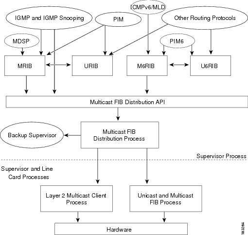
This figure shows the major components of the Cisco NX-OS multicast software architecture:
The Multicast FIB (MFIB and M6FIB) Distribution (MFDM) API defines an interface between the multicast Layer 2 and Layer 3 control plane modules, including the MRIB and M6RIB, and the platform forwarding plane. The control plane modules send the Layer 3 route update and Layer 2 lookup information using the MFDM API.
The multicast FIB distribution process distributes the multicast update messages to all the relevant modules and the standby supervisor. It runs only on the supervisor.
The Layer 2 multicast client process sets up the Layer 2 multicast hardware forwarding path. It runs on both the supervisor and the modules.
The unicast and multicast FIB process manages the Layer 3 hardware forwarding path. It runs on both the supervisor and the modules.
The Cisco NX-OS IPv4 Multicast Routing Information Base and IPv6 Multicast Routing Information Base (MRIB/M6RIB) dynamic shared memory support feature supports dynamic shared memory in a virtual device context (VDC). The MRIB/M6RIB dynamic shared memory feature changes the shared memory dynamically based on the number of routes that are added or removed from the MRIB/M6RIB. Instead of a static allocation of the entire configured memory for the multicast routes, the shared memory for MRIB/M6RIB dynamically adds up or is removed based on the increase or decrease, respectively, in the number of routes.
This feature also ensures that information on the shared memory is accessible and readable by the MRIB/M6RIB clients during a dynamic change in the shared memory. The MRIB/M6RIB dynamic shared memory feature also supports device switchover (from active to standy state and vice-versa) when the shared memory increases or decreases.
The MRIB and M6RIB maintain independent route information for each virtual routing and forwarding (VRF) instance in a virtual device context (VDC). VDC resource templates set the minimum and maximum limits for the shared memory when you create a VDC. The Cisco NX-OS software reserves the minimum limit for the resource to the VDC. Any resources allocated to the VDC beyond the minimum are based on the maximum limit and availability on the device. VDC templates set limits on both IPv4 multicast route memory and IPv6 multicast route memory. You can change the VDC resource limits by applying a new VDC resource template. Changes to the limits take effect immediately except for the IPv4 and IPv6 route memory limits, which take effect after the next VDC reset, physical device reload, or physical device stateful switchover. A switchover occurs when the active route processor (RP) fails, is removed from the networking device, or is manually taken down for maintenance.
Instead of a static allocation of the entire configured memory for the multicast routes, the shared memory for MRIB/M6RIB dynamically adds up or is removed based on the increase or decrease, respectively, in the number of routes, without making any modifications to the VDC.
The dynamic shared memory in MRIB/M6RIB is not affected during synchronization of the active and standby processors and during a physical device stateful switchover from the active to the standby processor.
A virtual port channel (vPC) allows a single device to use a port channel across two upstream switches. When you configure a vPC, the following multicast features may be affected:
PIM and PIM6—Cisco NX-OS software for the Nexus 7000 Series devices does not support PIM SSM or Bidr on a vPC.
GMP snooping—You should configure the vPC peers identically.
On the Cisco NX-OS software for the Nexus 7000 Series devices, the Maximum Transmission Unit (MTU) for a given mroute is equal to the smallest MTU of the OIF. Packets exceeding that MTU value are dropped and not multicast routed to any of the OIFs for that mroute.
Beginning with Cisco NX-OS Release 5.1, you can add an F Series module, which is a Layer 2-only module, into the Cisco Nexus 7000 Series chassis. When you add this module to a chassis that already contains M Series modules, you can provision multicasting.
Cisco NX-OS multicast features have the following restrictions:
Cisco Nexus 7000 Series devices do not support Pragmatic General Multicast (PGM).
After a multicast routing protocol is restarted, its state is recovered from the MRIB process. When a supervisor switchover occurs, the MRIB recovers its state from the hardware, and the multicast protocols recover their state from periodic message activity. For more information about high availability, see the Cisco Nexus 7000 Series NX-OS High Availability and Redundancy Guide.
|
Related Topic |
Document Title |
|---|---|
|
VDCs |
Cisco Nexus 7000 Series NX-OS Virtual Device Context Command Reference |
|
CLI Commands |
Cisco Nexus 7000 Series NX-OS Multicast Routing Command Reference |
|
Description |
Link |
|---|---|
|
Technical Assistance Center (TAC) home page, containing 30,000 pages of searchable technical content, including links to products, technologies, solutions, technical tips, and tools. Registered Cisco.com users can log in from this page to access even more content. |
 Feedback