Overview
The Cisco Nexus 9332D-H2R switch (N9K-C9332D-H2R) is a 1-rack unit (RU), fixed-port switch designed for deployment in data centers.
This switch includes the following ports:
-
400-Gigabit QSFP-DD ports (32)
-
10-Gigabit SFP+ ports (2)
-
Management ports (one 10/100/1000BASE-T port and one SFP port)
-
Console port (RS-232)
-
USB port
 Note |
ZRP optical modules can be plugged in the upper 16 ports only. |
This switch includes the following user-replaceable components:
-
Fan modules (6) with the following airflow choices:
-
Port-side intake fan module with burgundy coloring (NXA-SFAN-35CFM-PI)
-
-
Power supply modules (two—One for operations and one for redundancy [1+1]) with the following choices:
-
2000-W port-side intake AC power supply with burgundy coloring (NXA-PAC-2KW-PI)
-
2000-W port-side intake DC power supply with burgundy coloring (NXA-PDC-2KW-PI)
-
2000-W port-side intake HVDC power supply with burgundy coloring (NXA-PHV-2KW-PI)
Note
All fan modules and power supplies must use the same airflow direction.
Note
Each fan module has two rotors. The switch can function normally if one rotor inside the any one fan module fails. In case of more than one rotor failure, the switch will issue a warning and power down in 2 minute.
-
The following figure shows the switch features on the port side of the chassis.

|
1 |
Synchronous Ethernet (SyncE) DIN connector (1 PPS) |
2 |
Synchronous Ethernet (SyncE) DIN connector (10 MHz) |
|
3 |
10-Gigabit SFP+ port |
4 |
10-Gigabit SFP+ port |
|
5 |
400-Gigabit QSFP-DD ports (32) |
6 |
Time of Day (ToD) port |
|
7 |
Management port (RJ45) |
8 |
Management port (SFP) |
To determine which transceivers, adapters, and cables are support this switch, see the Cisco Transceiver Modules Compatibility Information document.
The following figure shows the switch features on the power supply side of the chassis.
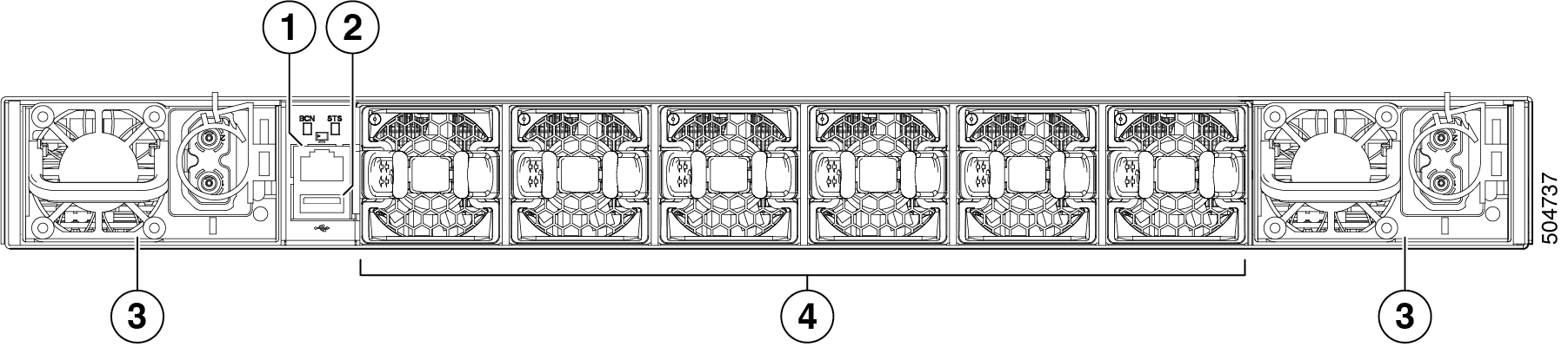
|
1 |
Console port |
2 |
USB port |
|
3 |
Power supply modules (1 or 2) (AC power supplies shown) with slots numbered 1 (left) and 2 (right) |
4 |
Fan modules (6) with slots numbered from 1 (left) to 6 (right) |
The following figure shows the side of the chassis.
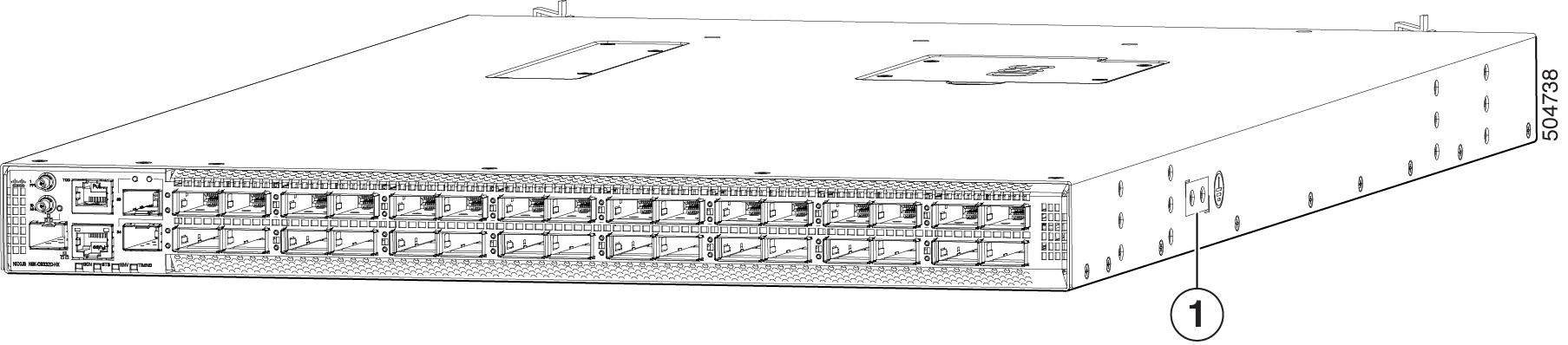
|
1 |
Grounding pad |
The fan and power supply modules are field replaceable. You can replace one fan module or one power supply module during operations so long as the other modules are installed and operating. If you have only one power supply installed, you can install the replacement power supply in the open slot before removing the original power supply.
 Caution |
If the switch has port-side intake airflow (burgundy coloring for fan modules), you must locate the ports in the cold aisle. If the switch has port-side exhaust airflow (blue coloring for fan modules), you must locate the ports in the hot aisle. If you locate the air intake in a hot aisle, the switch can overheat and shut down. |
 Feedback