Connecting the Switch to the ACI Fabric

ACI Fabric Topology

The ACI fabric topology includes the following major components:

  • Application Centric Infrastructure Controller (APIC) appliance (cluster of APICs)

  • Leaf switches (for switch compatibility, please see the data sheets).

  • Spine switches (for switch compatibility, please see the data sheets).

For additional information, please see the Cisco APIC Installation, Upgrade, and Downgrade Guide.


Note


To prevent sub-optimal forwarding between endpoints, connect every leaf switch in the fabric to every spine switch in the same fabric.


As shown in the following figure, each APIC is connected to one or two leaf switches and each leaf switch should be connected to every spine switch in the same fabric.

Figure 1. Connections Between APIC Clusters, Leaf Nodes, and Spine Nodes

Preparing to Connect to Other Devices

When preparing to connect the fabric devices, consider the following for each type of interface, and gather all of the required equipment before making the connections:

  • Cabling type required for each interface type

  • Distance limitations for each signal type

  • Additional interface equipment required


Note


When running power and data cables in overhead or subfloor cable trays, we strongly recommend that you locate power cables and other potential noise sources as far away as practical from network cabling that terminates on Cisco equipment. In situations where long parallel cable runs cannot be separated by at least 3.3 feet (1 meter), we recommend that you shield any potential noise sources by housing them in a grounded metallic conduit.


The optical transceivers that are not already assembled to their cables come separate from their cables. To prevent these transceivers and their cables from being damaged, we recommend that you keep the transceivers disconnected from their cables when installing them in ports and then insert the optical cable into the transceiver. When removing transceivers from ports, remove their cables before removing the transceivers.

To maximize the effectiveness and life of your transceivers and optical cables, do the following:

  • Wear an ESD-preventative wrist strap that is connected to an earth ground whenever handling transceivers. The switch is typically grounded when you install transceivers and provides an ESD port to which you can connect your wrist strap. If you cannot find an ESD port, connect the wrist strap to an earth ground (such as the grounding connection for the chassis).

  • Do not remove or insert a transceiver more often than necessary. Repeated removals and insertions can shorten its useful life.

  • Keep the transceivers and fiber-optic cables clean and dust free to maintain high signal accuracy and to prevent damage to the connectors. Attenuation (loss of light) increases with contamination and should be kept below 0.35 dB.

    • Clean these parts before installing them to prevent dust from scratching the fiber-optic cable ends.

    • Clean the connectors regularly; the required frequency of cleaning depends upon the environment. In addition, clean connectors if they are exposed to dust or accidentally touched. Both wet and dry cleaning techniques can be effective; refer to your site's fiber-optic connection cleaning procedures.

    • Do not touch the ends of connectors. Touching the ends can leave fingerprints and cause other contamination.

  • Inspect routinely for dust and damage. If you suspect damage, clean and then inspect fiber ends under a microscope to determine if damage has occurred.

Connecting Leaf Switches to APICs

You must downlink one or two (recommended for redundancy) Cisco Nexus 9300 platform ACI-mode leaf switches to each Application Policy Infrastructure Controller (APIC) in your ACI fabric. The type of virtual interface card (VIC) installed on the APIC determines the types of interface cables that you can use to connect the leaf switches to the APICs.

  • The VIC 1225T module supports copper connectors, copper cables, and switches with copper downlink ports (such as: Cisco Nexus 93108TC-FX switche).

  • The VIC 1225 module supports optical transceivers, optical cables, and switches with optical downlink ports (such as: Cisco Nexus 93600CD-GX switche).

  • The VIC 1455 module supports optical transceivers, optical cables, and switches with optical downlink ports (such as: Cisco Nexus 93600CD-GX switche).


Note


Breakout ports cannot be used for Cisco APIC connectivity.


Before you begin

The APIC and leaf switches in the fabric must be fully installed in their racks and grounded.


Note


When connecting an APIC to a 40-Gigabit interface, ensure that you use the CVR-QSFP-SFP10G adapter, which will automatically convert the interface to operate at 10-Gigabit. 40-Gigabit to 10-Gigabit breakout cables are not supported in this manner as they require manual configuration, which can only be done post fabric discovery.


Procedure


Step 1

Connect an interface cable to one of the two to four ports on the virtual interface card (VIC) installed on the APIC. If the cable is not already assembled to its transceivers, insert the transceiver into the VIC port and then connect the optical interface cable to the transceiver.

  • For a VIC 1225T 10GBASE-T copper module, use 10GBASE-T cables with RJ-45 connectors.

  • For a VIC 1225 optical module, use one of the following sets of transceivers and cables:

    • Cisco 10GBASE-LR transceivers (SFP-10G-LR) supporting a link length of up to 6.1 miles (10 km)

    • Cisco 10GBASE-SR transceivers (SFP-10G-SR) supporting the following link lengths:

      • Using 2000 MHz MMF (OM3) for up to 984 feet (300 m)

      • Using 4700 MHz MMF (OM4) for up to 1312 feet (400 m)

    • Cisco SFP+ Active Optical Cables (SFP-10G-AOCxM [where x=1, 3, 5, 7 for lengths in meters])

    • Cisco SFP+ Twinax Cables (SFP-H10GB-CUxM [where x=7 for lengths in meters])

  • For a VIC 1455 SFP28 module, 10-Gigabit only, use one of the following sets of transceivers and cables:

    • Cisco 10GBASE-LR transceivers (SFP-10G-LR) supporting a link length of up to 6.1 miles (10 km)

    • Cisco 10GBASE-SR transceivers (SFP-10G-SR) supporting the following link lengths:

      • Using 2000 MHz MMF (OM3) for up to 984 feet (300 m)

      • Using 4700 MHz MMF (OM4) for up to 1312 feet (400 m)

    • Cisco SFP+ Active Optical Cables (SFP-10G-AOCxM [where x=1, 2, 3, 5, 7, or 10 for lengths in meters])

    • Cisco SFP+ Twinax Cables (SFP-H10GB-CUxM [where x=1, 2, 3, 5, 7, or 10 for lengths in meters])

    Note


    The VIC 1455 has 4 ports, port-1, port-2, port-3, and port-4 from left to right.

    • All ports must have the same speed, either 10-Gigabit or 25-Gigabit.

    • Port-1 and port-2 is one pair, corresponding to eth2-1 on APIC and port-3 and port-4 is another pair, corresponding to eth2-2 on APIC. Only one connection is allowed for each pair. For example, you can connect one cable to either port-1 or port-2, and connect another cable to either port-3 or port-4 (please do not connect two cables on any pair).

    To determine which transceivers, adapters, and cables support this switch, see the Cisco Transceiver Modules Compatibility Information document.

    To see the transceiver specifications and installation information, see Transceiver Module Installation Guides.

Step 2

Connect the other end of the interface cable to a downlink port on a leaf switch.

  • For a Cisco 10GBASE-LR or -SR transceiver and cable, insert the transceiver into a downlink optical port on a leaf switch before connecting the cable to the transceiver.

  • For Cisco SFP+ Active Optical Cables, insert the transceiver on the cable into a downlink optical port on a leaf switch.

  • For a 10GBASE-T copper cable, insert the RJ-45 connector on the cable into a downlink BASE-T port on a leaf switch.

Note


To determine which transceivers, adapters, and cables support this switch, see the Cisco Transceiver Modules Compatibility Information document.


Connecting Leaf Switches to Spine Switches

For optimal forwarding between endpoints, you must connect each leaf switch to every spine switch in the same ACI fabric.

To determine which transceivers, adapters, and cables support this switch, see the Cisco Transceiver Modules Compatibility Information document.

To see the transceiver specifications and installation information, see Transceiver Module Installation Guides.


Warning


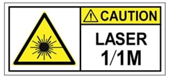
Statement 1055—Class 1/1M Laser

Invisible laser radiation is present. Do not expose to users of telescopic optics. This applies to Class 1/1M laser products.


Warning


Statement 1056—Unterminated Fiber Cable

Invisible laser radiation may be emitted from the end of the unterminated fiber cable or connector. Do not view directly with optical instruments. Viewing the laser output with certain optical instruments, for example, eye loupes, magnifiers, and microscopes, within a distance of 100 mm, may pose an eye hazard.


Before you begin

  • The leaf and spine switches in the fabric (such as: N9k-C9364C, N9K-C9332C, N9K-C9316D-GX, and N9K-C9332D-GX2B) must be fully installed in their racks and grounded.

  • If there are modular switches in the fabric, their ACI-mode line cards must already be installed. The line cards can be of the following types:

    • 32-port 100-Gigabit (such as: N9K-X9732C-EX)

    • 36-port 100-Gigabit (such as: N9K-X9736C-FX)

    • 16-port 400-Gigabit (such as: N9K-X9716D-GX)


Note


You cannot include NX-OS line cards in the same chassis when running in ACI mode.


Note


Multiple uplinks from a leaf switch to a spine switch is supported. A symmetrical topology is recommended so that all devices have equal access to resources.


Procedure


Step 1

For the transceivers with removable cables, make sure that the transceivers are separated from their interface cables.

Step 2

Insert the appropriate transceiver into an active uplink port on the leaf switch.

Step 3

Insert the same type of transceiver in the spine switch port on the line card.

Step 4

For transceivers with removable cables, insert the interface cable into the open end of each of those transceivers.

Step 5

Repeat Steps 1 through 4 for each spine switch in the ACI fabric.

The leaf switch is connected to each spine switch in the ACI fabric.

Step 6

Repeat Steps 1 through 5 for each leaf switch in the ACI fabric.

Each leaf switch in the ACI fabric is connected to each spine switch in the network,

The fabric automatically implements Equal Cost Multi-Pathing (ECMP) and enables all links. You do not need to configure the links.

Installing a Gigabit Ethernet module (GEM)

Procedure


Step 1

Clear the switch's current configuration by using the setup-clean-config command.

Step 2

Power off the switch by disconnecting the power.

Step 3

Replace the current GEM card with the new GEM card.

Step 4

Power on the switch.


Setting Up an Optional Console Interface

You can optionally set up a console interface for performing the initial configuration of the switch. To do this, use the interface cable provided in the accessory kit to connect the switch to your console device. You can connect the console port on the switch to a modem. If you do not connect it to a modem, make the connection either before powering up the switch or after completing the boot process for the switch.

Before you begin

The console device must support VT100 terminal emulations and asynchronous transmissions.

Procedure


Step 1

Configure the terminal emulator program to match each of the following default port characteristics:

  • 9600 baud

  • 8 data bits

  • 1 stop bit

  • No parity

Step 2

Insert the RJ-45 connector on the interface cable found in the accessory kit into the RS-232 port on the switch and insert the DB-9 connector on the other end of the cable to the serial port on the console device.


What to do next

You can now perform the initial configuration for the switch (see the Cisco ACI Getting Started Guide).

Setting Up an Optional Management Connection

You can optionally set up an out-of-band management connection for monitoring and troubleshooting purposes. To do this, depending on your switch, you connect either the RJ-45 management port or the SFP management port on the switch to an external hub, switch, or router.

Before you begin

To prevent an IP address conflict, you must complete the initial configuration for the switch and establish an IP address before you create the management connection.

Procedure


Step 1

Connect the interface cable to a management port on the switch.

  • For the RJ-45 management port, use a copper interface cable with RJ-45 connectors (can be used for shorter connections).

  • For the SFP management port, use an optical interface cable with LH or SX SFP transceivers (can be used for longer connections).

Note


If you use the management interface, connect only one of the two management ports. The switch does not support your use of two management ports at the same time.

Step 2

Connect the other end of the cable to an external hub, switch, or router.


Maintaining Transceivers and Optical Cables

Transceivers and fiber-optic cables must be kept clean and dust free to maintain high signal accuracy and prevent damage to the connectors. Contamination increases attenuation (loss of light) and should be below 0.35 dB.

Consider these maintenance guidelines:

  • Transceivers are static sensitive. To prevent ESD damage, wear an ESD-preventative wrist strap that is connected to the grounded chassis.

  • Do not remove and insert a transceiver more often than is necessary. Repeated removals and insertions can shorten its useful life.

  • Keep all optical connections covered when not in use. Clean them before using to prevent dust from scratching the fiber-optic cable ends.

  • Do not touch the ends of connectors. Touching the ends can leave fingerprints and cause other contamination.

  • Clean the connectors regularly; the required frequency of cleaning depends upon the environment. In addition, clean connectors if they are exposed to dust or accidentally touched. Both wet and dry cleaning techniques can be effective; refer to the fiber-optic connection cleaning procedures for your site.

  • Inspect routinely for dust and damage. If you suspect damage, clean and then inspect fiber ends under a microscope to determine if damage has occurred.