Configuring PTP

This chapter describes how to configure the Precision Time Protocol (PTP) on Cisco NX-OS devices.

This chapter includes the following sections:

About PTP

PTP is a time synchronization protocol defined in IEEE 1588 for nodes distributed across a network. With PTP, it is possible to synchronize distributed clocks with an accuracy of less than 1 microsecond via Ethernet networks. In addition, PTP's hardware timestamping feature provides timestamp information in the ERSPAN Type III header that can be used to calculate packet latency among edge, aggregate, and core switches.

A PTP system can consist of a combination of PTP and non-PTP devices. PTP devices include ordinary clocks, boundary clocks, and transparent clocks. Non-PTP devices include ordinary network switches, routers, and other infrastructure devices.

PTP is a distributed protocol that specifies how real-time PTP clocks in the system synchronize with each other. These clocks are organized into a master-slave synchronization hierarchy with the grandmaster clock, which is the clock at the top of the hierarchy, determining the reference time for the entire system. Synchronization is achieved by exchanging PTP timing messages, with the members using the timing information to adjust their clocks to the time of their master in the hierarchy. PTP operates within a logical scope called a PTP domain.

PTP supports the following functionality:

  • Multicast and unicast PTP transport—In the multicast transport mode, PTP uses multicast destination IP address 224.0.1.129 as per IEEE 1588 standards for communication between devices. For the source IP address, it uses the user configurable global IP address under the PTP domain. In the unicast transport mode, PTP uses configurable unicast source and destination IP addresses that can be configured under an interface. In both, the unicast and the multicast modes, PTP uses UDP ports, 319 for event messages and 320 for general messages communication between devices.

  • PTP multicast configuration is supported only under physical interface for L2 or L3. Unicast PTP configuration supported only under L3 physical interface. PTP is not supported for virtual interfaces such as Port-channel, SVI, and tunnel.

  • PTP encapsulation over UDP over IP—PTP uses UDP as the transport protocol over IP. In both, the unicast and multicast modes, PTP uses UDP ports 319 for event messages and 320 for general messages communication between devices. L2 encapsulation mode is not supported in Cisco NX-OS Release 7.0(3)F3(3).

  • PTP profiles—PTP supports default (1588) , AES67, and SMPTE 2059-2 profiles. They all have different ranges of sync and delay request intervals. For information on the default profile, refer to IEEE 1588. For more information on AES67 and SMPTE 2059-2, refer to the respective specifications.

  • Path delay measurement—We support delay request and response mechanism to measure the delay between the master and slave devices. Peer delay request and response mechanism is not supported in Cisco NX-OS Release 7.0(3)F3(3).

  • Message intervals—You can configure the interval at which the announce, sync, and delay request messages needs to be sent between devices.

  • Best master clock (BMC) selection—BMC algorithm is used to select master, slave, and passive states of the PTP enabled interfaces based on the Announce message received as per 1588 specification.

PTP Device Types

The PTP device type is configurable and can be used to set the clock type.

Clocks

The following clocks are common PTP devices:

Ordinary clock

Communicates with the network based on a single physical port, similar to an end host. An ordinary clock can function as a grandmaster clock.

Boundary clock

Typically has several physical ports, with each port behaving like a port of an ordinary clock. However, each port shares the local clock, and the clock data sets are common to all ports. Each port decides its individual state, either master (synchronizing other ports connected to it) or slave (synchronizing to a downstream port), based on the best clock available to it through all of the other ports on the boundary clock. Messages related to synchronization and establishing the master-slave hierarchy terminate in the protocol engine of a boundary clock and are not forwarded.

Transparent clock

Forwards all PTP messages like an ordinary switch or router but measures the residence time of a packet in the switch (the time that the packet takes to traverse the transparent clock) and in some cases the link delay of the ingress port for the packet. The ports have no state because the transparent clock does not need to synchronize to the grandmaster clock.

There are two kinds of transparent clocks:

End-to-end transparent clock

Measures the residence time of a PTP message and accumulates the times in the correction field of the PTP message or an associated follow-up message.

Peer-to-peer transparent clock

Measures the residence time of a PTP message and computes the link delay between each port and a similarly equipped port on another node that shares the link. For a packet, this incoming link delay is added to the residence time in the correction field of the PTP message or an associated follow-up message.


Note


PTP operates only in boundary clock mode. Cisco recommends deployment of a Grand Master Clock (10 MHz) upstream, with servers containing clocks requiring synchronization connected to the switch.

End-to-end transparent clock and peer-to-peer transparent clock modes are not supported.


PTP Process

The PTP process consists of two phases: establishing the master-slave hierarchy and synchronizing the clocks.

Within a PTP domain, each port of an ordinary or boundary clock follows this process to determine its state:

  • Examines the contents of all received announce messages (issued by ports in the master state)

  • Compares the data sets of the foreign master (in the announce message) and the local clock for priority, clock class, accuracy, and so on

  • Determines its own state as either master or slave

The ordinary and boundary clocks use Sync , Delay_Req , Follow_Up , Delay_Resp event messages to generate and communicate timing information.

These messages are sent in the following sequence:

  1. The master sends a Sync message to the slave and notes the time, t1 at which it was sent. For one-step Sync message carries the time when the message leaves the master and for two-step this time is sent in the subsequent Follow-Up event message.

  2. The slave receives the Sync message and notes the time of reception, t2.

  3. The master conveys to the slave the timestamp, t1 by embedding the timestamp in a Follow_Up event message.

  4. The slave sends a Delay_Req message to the master and notes the time, t3 at which it was sent.

  5. The master receives the Delay_Req message and notes the time of reception, t4.

  6. The master conveys to the slave the timestamp, t4 by embedding it in a Delay_Resp message.

  7. After this sequence, the slave possesses all four timestamps. These timestamps can be used to compute the offset of the slave clock relative to the master, and the mean propagation time of messages between the two clocks.

    The following figure describes the event messages in the PTP process that generate and communicate timing information.

    Figure 1. PTP Process
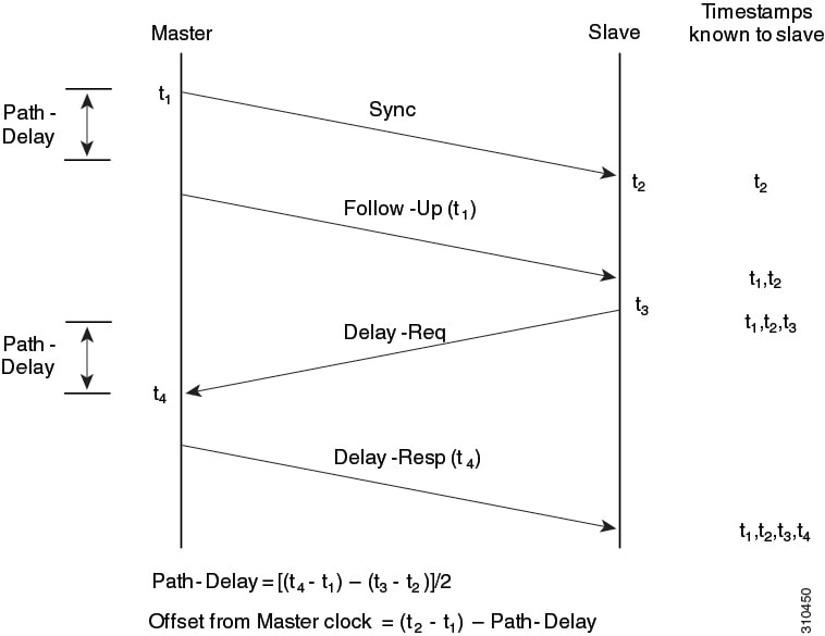
    Event messages that generate and communicate timing information

Guidelines and Limitations for PTP


Note


For scale information, see the release-specific Cisco Nexus 9000 Series NX-OS Verified Scalability Guide.


  • To match PTP control packets using RACL, enable PIM on the L3 interface.

  • When PTP is configured on a Cisco Nexus 9000 series switch, set the clock protocol to use PTP through theclock protocol ptp vdc 1 command. NTP cannot coexist with PTP on a Cisco Nexus 9000 series switch.

  • PTP is supported for all Cisco Nexus 9000 Series and 3164Q hardware except for the 100G 9408PC line card and the 100G M4PC generic expansion module (GEM). The Cisco Nexus 9300-FX platform switches support PTP beginning with Cisco NX-OS Release 7.0(3)I7(1).

  • PTP operates only in boundary clock mode. End-to-end transparent clock and peer-to-peer transparent clock modes are not supported.

  • PTP supports transport over User Datagram Protocol (UDP). Transport over Ethernet is not supported.

  • One-step PTP is only supported on Cisco Nexus 9000-R series platform switches.

  • PTP supports multicast communication. Beginning with Cisco NX-OS Release 7.0(3)I4(5), PTP also supports unicast communication and the unicast mode is optional.

  • Timestamp Tagging (TTAG) is supported on the following platform switches:

    • Cisco Nexus 9200 platform switches: beginning with Cisco NX-OS Release 7.0(3)I6(1)

    • Cisco Nexus 9364C: beginning with Cisco NX-OS Release 7.0(3)I7(2)

    • Cisco Nexus 9300-EX platform switches: beginning with Cisco NX-OS Release (7.0(3)I6(1)

    • Cisco Nexus 9300-FX platform switches: beginning with Cisco NX-OS Release 7.0(3)I7(3)

    • Cisco Nexus 9500 platform switches with -EX and -FX line cards

  • Beginning with Cisco NX-OS Release 7.0(3)F3(3), PTP supports unicast communication on Cisco Nexus 9508 switches with 9636C-R, 9636C-RX, and 9636Q-R line cards. For PTP to work, you must use the latest SUP and LC FPGA versions.

  • Beginning in Cisco NX-OS Release 7.0(3)I7(2) the Cisco Nexus 9000 Series switches support mixed non-negotiated mode of operation on master PTP ports. Meaning that when a slave client sends unicast delay request PTP packet, the Cisco Nexus 9000 responds with an unicast delay response packet. And, if the slave client sends multicast delay request PTP packet, the Cisco Nexus 9000 responds with a multicast delay response packet. For mixed non-negotiated mode to work, the source IP address used in the ptp source <IP address> configuration on the BC device must also be configured on any physical or logical interface of the BC device. The recommended best practice is to use the loopback interface of the device.

  • Beginning with Cisco NX-OS Release 7.0(3)I6(1), Cisco Nexus 93108TC-EX and 93180YC-EX switches support PTP mixed mode and unicast mode. Beginning with Cisco NX-OS Release 7.0(3)I7(1), the Cisco Nexus 9396 switch supports PTP mixed mode.

  • Beginning with Cisco NX-OS Release 7.0(3)F3(3), PTP unicast mode on the Layer2 SVI interfaces is not supported on Cisco Nexus 9508 switches with 9636C-R, 9636C-RX, and 9636Q-R line cards.

  • Beginning with Cisco NX-OS Release 7.0(3)F3(3), PTP configuration with UC and MC on either sides is not supported on Cisco Nexus 9508 switches with 9636C-R and 9636Q-R line cards.

  • PTP is limited to a single domain per network.

  • All management messages are forwarded on ports on which PTP is enabled. Handling management messages is not supported.

  • Beginning with Cisco NX-OS Release 7.0(3)F3(3), forwarding PTP management packets is supported on Cisco Nexus 9508 switches with 9636C-R, 9636C-RX, and 9636Q-R line cards.

  • PTP is not supported on FEX interfaces.

  • PTP-capable ports do not identify PTP packets and do not time-stamp or redirect those packets unless you enable PTP on those ports.

  • PTP can be enabled on port-channel member ports.

  • Beginning with Cisco NX-OS Release 7.0(3)I6(1), Cisco Nexus 9732C-EX, 9736C-EX, and 97160YC-EX line cards support PTP offloading.

  • Beginning with Cisco NX-OS Release 7.0(3)I6(1), Cisco Nexus 9732C-EX, 9736C-EX, and 97160YC-EX line cards support timestamp tagging.

  • We recommend that the PTP device can either have multicast or unicast PTP mode configured, but not both multicast and unicast mode together.

  • We recommend that you have the one-step or two-step PTP in the PTP device and the associated downstream switches.

  • Unicast negotiation is not supported for IPv4 unicast communication for all Nexus 9000 switches.

Default Settings for PTP

The following table lists the default settings for PTP parameters.

Table 1. Default PTP Parameters
Parameters Default

PTP

Disabled

PTP version

2

PTP domain

0

PTP priority 1 value when advertising the clock

255

PTP priority 2 value when advertising the clock

255

PTP announce interval

1 log second

PTP announce timeout

3 announce intervals

PTP delay-request interval

  • 0 log seconds

  • -1 log seconds for Cisco Nexus 3232C, 3264Q, and 9500 platform switches

PTP sync interval

  • -2 log seconds

  • -3 log seconds for Cisco Nexus 3232C, 3264Q, and 9500 platform switches

PTP VLAN

gPTP supports only default vlan 1, and no other user configured VLANs.

Configuring PTP

Configuring PTP Globally

You can enable or disable PTP globally on a device. You can also configure various PTP clock parameters to help determine which clock in the network has the highest priority to be selected as the grandmaster.


Note


You must always set the clock protocol PTP vdc1 for the local clock to be updated by the PTP protocol, irrespective of the one-step or the two-step mode. You can verify the configuration using the show running-config clock_manager command.

Procedure

  Command or Action Purpose

Step 1

configure terminal

Example:

switch# configure terminal
switch(config)#

Enters global configuration mode.

Step 2

[no] feature ptp

Example:

switch(config)# feature ptp

Enables or disables PTP on the device.

Note


Enabling PTP on the switch does not enable PTP on each interface.

Step 3

[no] ptp device-type [generalized-ptp | boundary-clock]

Example:

switch(config)# ptp device-type generalized-ptp
Configures the device type as gPTP or boundary clock. The generalized-ptp option is available only for Cisco Nexus 9508 switches with an -R series line card, beginning with Cisco NX-OS Release 7.0(3)PTP0(15).

Step 4

[no] ptp source ip-address

Example:

switch(config)# ptp source 10.10.10.1

Configures the source IPv4 address for all the PTP packets in the multicast PTP mode.

Step 5

(Optional) [no] ptp domain number

Example:

switch(config)# ptp domain 1
(Optional)

Configures the domain number to use for this clock. PTP domains allow you to use multiple independent PTP clocking subdomains on a single network.

The range for the number is from 0 to 127.

Step 6

(Optional) [no] ptp priority1 value

Example:

switch(config)# ptp priority1 1
(Optional)

Configures the priority1 value to use when advertising this clock. This value overrides the default criteria (clock quality, clock class, and so on) for best master clock selection. Lower values take precedence.

The range for the value is from 0 to 255.

Note


For the switch to synchronize with an external Grand Master clock, the local switch PTP priority value must be configured higher than that of external Grand Master Clock priority.

Step 7

(Optional) [no] ptp priority2 value

Example:

switch(config)# ptp priority2 1
(Optional)

Configures the priority2 value to use when advertising this clock. This value is used to decide between two devices that are otherwise equally matched in the default criteria. For example, you can use the priority2 value to give a specific switch priority over other identical switches.

The range for the value is from 0 to 255.

Note


For the switch to synchronize with an external Grand Master clock, the local switch PTP priority value must be configured higher than that of external Grand Master Clock priority.

Step 8

[ no ] ptp management

Example:

switch(config)# ptp management
switch(config-ptp-profile)#

Configures support for PTP management packets. This command is enabled by default.

no : Disables support for management packets.

Step 9

(Optional) copy running-config startup-config

Example:

switch(config)# copy running-config startup-config
(Optional)

Copies the running configuration to the startup configuration.

Configuring PTP on an Interface

After you globally enable PTP, it is not enabled on all supported interfaces by default. You must enable PTP interfaces individually.

Before you begin

Make sure that you have globally enabled PTP on the switch and configured the source IP address for PTP communication.

Procedure

  Command or Action Purpose

Step 1

configure terminal

Example:

switch# configure terminal
switch(config)#

Enters global configuration mode.

Step 2

interface ethernet slot/port

Example:

switch(config)# interface ethernet 2/1
switch(config-if)#

Specifies the interface on which you are enabling PTP and enters the interface configuration mode.

Step 3

[no] ptp

Example:

switch(config-if)# ptp

Enables or disables PTP on an interface.

Step 4

(Optional) [ no ] ptp master ipv6-address

Example:

switch(config-if)# ptp master 10.10.10.1
switch(config-if)#
(Optional)

Sets the IP address of the master clock when the PTP role of the interface is set to "slave".

This option is only available for PTP Telecom Profile on the Cisco Nexus 93180YC-FX3S switch.

Note


This command is supported beginning with Cisco NX-OS Release 10.2(1)F.

Step 5

(Optional) ptp transport ipv4 ucast master

Example:

switch(config)# ptp transport ipv4 ucast master
(Optional)

Enables PTP on the interface in an unicast mode (PTP master use).

Step 6

(Optional) ptp transport ipv4 ucast slave

Example:

switch(config)# ptp transport ipv4 ucast slave
(Optional)

Enables PTP on the interface in an unicast mode (PTP slave use).

Step 7

(Optional) ptp ucast-source ipv4-address [ vrf vrf-name ]

Example:

switch(config)# ptp ucast-source 10.1.1.40
(Optional)

Configures the source IP address for unicast messages.

ipv4-address : The IPv4 address of the unicast source.

vrf vrf-name: The name of the VRF used for hello messages.

Step 8

(Optional) [no] ptp announce {interval log-seconds | timeout count}

Example:

switch(config-if)# ptp announce interval 3
(Optional)

Configures the interval between PTP announce messages on an interface or the number of PTP intervals before a timeout occurs on an interface.

The range for the PTP announcement interval is from 0 to 4 log seconds, and the range for the interval timeout is from 2 to 4 intervals.

Step 9

(Optional) [no] ptp announce interval [aes67 | smpte-2059] log-seconds

Example:

switch(config-if)# ptp announce interval aes67 3
(Optional)

Configures the interval between PTP announce messages on an interface.

Table 2. PTP Announcement Interval Range and Default Values

Option

Range

Default Value

aes67-2015

0 to 4 log seconds

1 log second

smpte-2059-2

–3 to 1 log seconds

1 log second

Without the aes67 or smpte-2059 option

0 to 4 log seconds

1 log second

Step 10

(Optional) [no] ptp delay-request minimum interval log-seconds

Example:

switch(config-if)# ptp delay-request minimum interval -1
(Optional)

Configures the minimum interval allowed between PTP delay messages when the port is in the master state.

The range is from log(–1) to log(6) seconds, where log(–1) = 2 frames every second.

Step 11

(Optional) [no] ptp delay-request minimum interval [aes67-2015 | smpte-2059-2] log-seconds

Example:

switch(config-if)# ptp delay-request minimum interval aes67-2015-1
(Optional)

Configures the minimum interval allowed between PTP delay messages when the port is in the master state.

Table 3. PTP Delay-Request Minimum Interval Range and Default Values

Option

Range

Default Value

aes67-2015

–4 to 5 log seconds

0 log seconds

smpte-2059-2

–4 to 5 log seconds

0 log seconds

Without the aes67-2015 or smpte-2059-2 option

–1 to 6 log seconds (where –1 = 2 frames every second)

0 log seconds

Step 12

(Optional) [no] ptp sync interval log-seconds

Example:

switch(config-if)# ptp sync interval 1
(Optional)

Configures the interval between PTP synchronization messages on an interface.

The range is from log(–3) to log(1) seconds. For the media-related profile information, see the Cisco NX-OS IP Fabric for Medial Solution Guide when configuring PTP for media.

Step 13

(Optional) [no] ptp sync interval [aes67-2015 | smpte-2059-2] log-seconds

Example:

switch(config-if)# ptp sync interval aes67 1
(Optional)

Configures the interval between PTP synchronization messages on an interface.

Table 4. PTP Synchronization Interval Range and Default Values

Option

Range

Default Value

aes67-2015

–4 to 1 log seconds

–2 log seconds

smpte-2059-2

–4 to –1 log seconds

–2 log seconds

Without the aes67-2015 or smpte-2059-2 option

–3 to 1 log seconds

–2 log seconds

Step 14

(Optional) [no] ptp vlan vlan-id

Example:

switch(config-if)# ptp vlan 1
(Optional)

Specifies the VLAN for the interface where PTP is being enabled. You can only enable PTP on one VLAN on an interface.

The range is from 1 to 4094.

Step 15

(Optional) show ptp brief

Example:

switch(config-if)# show ptp brief
(Optional)

Displays the PTP status.

Step 16

(Optional) show ptp port interface interface slot/port

Example:

switch(config-if)# show ptp port interface ethernet 2/1
(Optional)

Displays the status of the PTP port.

Step 17

(Optional) copy running-config startup-config

Example:

switch(config-if)# copy running-config startup-config
(Optional)

Copies the running configuration to the startup configuration.

Configuring PTP in Unicast Mode

Configuring Unicast Mode

Traditional PTP messages are delivered to the nodes that are capable of receiving PTP multicast messages. (For example, announce , sync , delay_req , delay_resp and follow_up ). In Unicast mode, all PTP messages are delivered only to a particular PTP node. Multicast address is not used. In unicast mode, you can configure master/slave role and assign corresponding peer slave/master IP addresses.

Up to 8 master IPs can be configured for a slave unicast port and 64 slave IPs can be configured for a master port with a maximum 256 slave IP total for all ports. The following commands are used to configure the unicast slave IPs and unicast master IPs. Unicast packets are only sent to and received from these IPs. Packets received from other IPs are ignored.

switch(config-if)# ptp transport ipv4 ucast master 
switch(config-if-ptp-master)# slave ipv4 10.10.10.2 

switch(config-if)# ptp transport ipv4 ucast slave 
switch(config-if-ptp-slave)# master ipv4 10.10.10.1 

Assigning Master Role

Complete the following steps to assign a master role:

Procedure
  Command or Action Purpose

Step 1

configure terminal

Example:
switch# configure terminal
switch(config)#

Enters global configuration mode.

Step 2

interface ethernet slot/port

Example:
switch(config)# interface ethernet 2/1
switch(config-if)#

Specifies the interface on which you are enabling PTP and enters the interface configuration mode.

Step 3

[no ] ptp transport ipv4 ucast master

Example:
switch(config-if)# ptp transport ipv4 ucast master
switch(config-if-ptp-master)#

Enables PTP master on a particular port (Layer 3 interface). In the master sub-mode, you can enter the slave IPv4 addresses.

Step 4

slave ipv4 <IP_address>

Example:
switch-1(config)# interface ethernet 1/1
switch-1(config-if)# ptp transport ipv4 ucast master
switch-1(config-if-ptp-master)# slave ipv4 1.2.3.1
switch-1(config-if-ptp-master)# slave ipv4 1.2.3.2
switch-1(config-if-ptp-master)# slave ipv4 1.2.3.3
switch-1(config-if-ptp-master)# slave ipv4 1.2.3.4
switch-1(config-if-ptp-master)#

Enters the slave IPv4 addresses. Maximum of 64 IP addresses are allowed per master, but this number varies and it depends on the sync interval configuration. The master sends announce, sync, follow-up, and delay_resp only to these slave addresses. You must make sure that the slave IP is reachable.

Assigning Slave Role

Complete the following steps to assign a slave role:

Procedure
  Command or Action Purpose

Step 1

configure terminal

Example:
switch# configure terminal
switch(config)#

Enters global configuration mode.

Step 2

interface ethernet slot/port

Example:
switch(config)# interface ethernet 2/1
switch(config-if)#

Specifies the interface on which you are enabling PTP and enters the interface configuration mode.

Step 3

[no ] ptp transport ipv4 ucast slave

Example:
switch(config-if)# ptp transport ipv4 ucast slave
switch(config-if-ptp-slave)#

Enables PTP slave on a particular port (Layer 3 interface). In the slave sub-mode, you can enter the master IPv4 addresses.

Step 4

master ipv4 <IP_address>

Example:

switch-1(config)# interface ethernet 1/1
switch-1(config-if)# ptp transport ipv4 ucast slave
switch-1(config-if-ptp-slave)# master ipv4 4.4.4.1
switch-1(config-if-ptp-slave)# master ipv4 4.4.4.2
switch-1(config-if-ptp-slave)# master ipv4 4.4.4.3

Enters the master IPv4 addresses.

Configuring Unicast Source Address


Note


For all releases up to, and including Cisco NX-OS Release 9.3(4), if the PTP configuration on the interface is changed from unicast to multicast or unicast slave to unicast master, you must reconfigure the unicast source address.


Complete the following steps to configure unicast source address:

Procedure
  Command or Action Purpose

Step 1

configure terminal

Example:
switch# configure terminal
switch(config)#

Enters global configuration mode.

Step 2

interface ethernet slot/port

Example:
switch(config)# interface ethernet 2/1
switch(config-if)#

Specifies the interface on which you are enabling PTP and enters the interface configuration mode.

Step 3

[no] ptp ucast-source ipv4-address

Example:
switch(config-if)# ptp ucast-source 10.10.10.20
switch(config-if)#

Configure PTP source address per interface level. This IP address is used only for unicast PTP messages. The PTP unicast source IP address must be reachable.

Timestamp Tagging

The timestamp tagging feature provides precision time information to track in real time when packets arrive at remote devices. Packets are truncated and timestamped using PTP with nanosecond accuracy. Using the TAP aggregation functionality on the switch, along with the Cisco Nexus Data Broker, you can copy the network traffic using SPAN, filter and timestamp the traffic, and send it for recording and analysis.

Configuring Timestamp Tagging


Note


Configuring timestamp tagging is not supported on Cisco Nexus 9508 switches with 9636C-R, 9636C-RX, and 9636Q-R line cards.

Note


When you use the ttag feature in a VXLAN EVPN multisite deployment, make sure that the ttag is stripped (ttag-strip ) on BGW's DCI interfaces that connect to the cloud. To elaborate, if the ttag is attached to non-Nexus 9000 devices that do not support ether-type 0x8905, stripping of ttag is required. However, BGW back-to-back model of DCI does not require ttag stripping.


Before you begin

Make sure that you have globally enabled PTP offloading.

Procedure

  Command or Action Purpose

Step 1

configure terminal

Example:

switch# configure terminal
switch(config)#

Enters global configuration mode.

Step 2

interface type slot/port

Example:

switch(config)# interface ethernet 2/2
switch(config-if)# 

Enters interface configuration mode for the specified interface.

Step 3

[no] ttag

Example:

switch(config-if)# ttag

Configures timestamp tagging on the Layer 2 or Layer 3 egress interface.

Configuring the TTAG Marker Packets and Time Interval

The ttag timestamp field attaches a 48-bit timestamp on the marker packet. This 48-bit timestamp is not a human familiar ASCII based timestamp. To make this 48-bit timestamp human readable, the ttag marker packet can be used to provide additional information to decode the 48-bit timestamp information.

Field

Position (byte:bit)

Length

Definition

Magic

16

By default, this field displays A6A6. This enables to identify ttag-marker packets on the packet stream.

Version

8

Version number. The default version is 1.

Granularity

16

This field represents the granularity of the 48-bit timestamp size. By default, the value is 04, which is 100 picoseconds or 0.1. nanoseconds.

UTc_offset

8

The utc_offset between the ASIC and the UTC clocks. The default value is 0.

Timestamp_hi

32

The high 16-bit of 48- bit ASIC hardware timestamp.

Timestamp_lo

32

The low 32-bit of 48- bit ASIC hardware timestamp.

UTC sec

32

The seconds part of UTC timestamp from the CPU clock of the Cisco Nexus 9000 Series switch.

UTC nsec

32

The nanoseconds part of UTC timestamp from the CPU clock of the Cisco Nexus 9000 Series switch.

Reserved

32

Reserved for future use.

Signature

32

The default value is 0xA5A5A5A5. This allows a forward search of marker packet and provide references to the UTC timestamp, so the client software can use that reference UTC to recover the 32-bit hardware timestamp in each packet header.

Pad

8

This is align byte to convert the ttag-marker align to 4 byte boundary.

Before you begin

Make sure that you have globally enabled PTP offloading.

Procedure

  Command or Action Purpose

Step 1

configure terminal

Example:

switch# configure terminal
switch(config)#

Enters global configuration mode.

Step 2

ttag-marker-interval seconds

Example:

switch(config-if)# ttag-marker-interval 90

Configures the seconds that a switch will take to send a ttag-marker packet to the outgoing ports. This is a global setting to the switch. By default, it sends a ttag-marker packet every 60 seconds. The range for seconds is from 1 to 25200.

Step 3

interface type slot/port

Example:

switch(config)# interface ethernet 2/2
switch(config-if)# 

Enters interface configuration mode for the specified interface.

Step 4

[no] ttag-marker enable

Example:

switch(config-if)# ttag-marker enable

Sends the ttag-marker packets to the outgoing port.

Step 5

ttag-strip

Example:

switch(config-if)# ttag-strip

Removes TTAG from egress packets on the interface.

Verifying the PTP Configuration

Use one of the following commands to verify the configuration:

Table 5. PTP Show Commands
Command Purpose
show ptp brief

Displays the PTP status.

show ptp clock

Displays the properties of the local clock, including clock identity.

show ptp clock foreign-masters-record

Displays the state of foreign masters known to the PTP process. For each foreign master, the output displays the clock identity, basic clock properties, and whether the clock is being used as a grandmaster.

show ptp corrections

Displays the last few PTP corrections.

show ptp counters [all | interface ethernet slot/port]

Displays the PTP packet counters for all interfaces or for a specified interface.

show ptp parent

Displays the properties of the PTP parent.

show ptp port interface ethernet slot/port

Displays the status of the PTP port on the switch.

show ptp time-property

Displays the PTP clock properties.

show ttag brief

Displays the status of the timestamp tagging configuration.

Note

 
Timestamp tagging configuration is not supported on Cisco Nexus 9508 switches with 9636C-R, 9636C-RX, and 9636Q-R line cards.
show running-config ptp [all]

Displays the running configuration for PTP.

clear ptp counters [all | interface ethernet slot/port]

Clears all PTP messages that are received and transmitted on a specific interface or on all interfaces that has PTP enabled.

clear ptp corrections

Clears the history of the PTP corrections.

Configuration Examples for PTP

This example shows how to configure PTP globally on the device, specify the source IP address for PTP communications, and configure a preference level for the clock:

switch# configure terminal
switch(config)# feature ptp
switch(config)# ptp source 10.10.10.1
switch(config)# ptp priority1 1
switch(config)# ptp priority2 1
switch(config)# show ptp brief
PTP port status
-----------------------
Port State
------- --------------
switch(config)# show ptp clock
PTP Device Type: Boundary clock
Clock Identity : 0:22:55:ff:ff:79:a4:c1
Clock Domain: 0
Number of PTP ports: 0
Priority1 : 1
Priority2 : 1
Clock Quality:
  Class : 248
  Accuracy : 254
  Offset (log variance) : 65535
Offset From Master : 0
Mean Path Delay : 0
Steps removed : 0
Local clock time:Mon Dec 22 14:13:24 2014

This example shows how to configure PTP on an interface and configure the intervals for the announce, delay-request, and synchronization messages:

switch# configure terminal
switch(config)# interface Ethernet 1/1
switch(config-if)# ptp
switch(config-if)# ptp announce interval 3
switch(config-if)# ptp announce timeout 2
switch(config-if)# ptp delay-request minimum interval smpte-2059-2 -3
switch(config-if)# ptp sync interval smpte-2059-2 -3
switch(config-if)# no shutdown
switch(config-if)# show ptp brief
PTP port status
-----------------------
Port State
------- --------------
Eth2/1 Master
switch(config-if)# show ptp port interface ethernet 2/1
PTP Port Dataset: Eth2/1
Port identity: clock identity: 0:22:55:ff:ff:79:a4:c1
Port identity: port number: 1028
PTP version: 2
Port state: Master
Delay request interval(log mean): 4
Announce receipt time out: 2
Peer mean path delay: 0
Announce interval(log mean): 3
Sync interval(log mean): 1
Delay Mechanism: End to End
Peer delay request interval(log mean): 0

This example shows how to configure master/slave role and assign corresponding peer slave/master IP addresses.


For Cisco NX-OS Release 9.3(4) and earlier:
switch-1(config)# interface ethernet 1/1
switch-1(config-if)# ptp transport ipv4 ucast master
switch-1(config-if-ptp-master)# slave ipv4 1.2.3.1
switch-1(config-if-ptp-master)# slave ipv4 1.2.3.2
switch-1(config-if-ptp-master)# slave ipv4 1.2.3.3
switch-1(config-if-ptp-master)# slave ipv4 1.2.3.4
switch-1(config-if-ptp-master)#

switch-1(config-if)# ptp transport ipv4 ucast slave
switch-1(config-if-ptp-slave)# master ipv4 4.4.4.1
switch-1(config-if-ptp-slave)# master ipv4 4.4.4.2
switch-1(config-if-ptp-slave)# master ipv4 4.4.4.3


switch-1(config-if-ptp-slave)# ptp ucast-source 9.9.9.9


switch-1(config-if)# sh running-config ptp

!Command: show running-config ptp
!Time: Tue Feb  7 17:37:09 2017

version 7.0(3)I4(6)
feature ptp

ptp source 1.1.1.1


interface Ethernet1/1
  ptp transport ipv4 ucast master
    slave ipv4 1.2.3.1
    slave ipv4 1.2.3.2
    slave ipv4 1.2.3.3
    slave ipv4 1.2.3.4

interface Ethernet1/2
  ptp transport ipv4 ucast slave
    master ipv4 4.4.4.1
    master ipv4 4.4.4.2
    master ipv4 4.4.4.3
  ptp ucast-source 9.9.9.9

switch-1(config-if)#