Configuring VXLAN OAM

This chapter contains the following sections:

VXLAN OAM Overview

The VXLAN operations, administration, and maintenance (OAM) protocol is a protocol for installing, monitoring, and troubleshooting Ethernet networks to enhance management in VXLAN based overlay networks.

Similar to ping, traceroute, or pathtrace utilities that allow quick determination of the problems in the IP networks, equivalent troubleshooting tools have been introduced to diagnose the problems in the VXLAN networks. The VXLAN OAM tools, for example, ping, pathtrace, and traceroute provide the reachability information to the hosts and the VTEPs in a VXLAN network. The OAM channel is used to identify the type of the VXLAN payload that is present in these OAM packets.

There are two types of payloads supported:

  • Conventional ICMP packet to the destination to be tracked

  • Special NVO3 draft Tissa OAM header that carries useful information

The ICMP channel helps to reach the traditional hosts or switches that do not support the new OAM packet formats. The NVO3 draft Tissa channels helps to reach the supported hosts or switches and carries the important diagnostic information. The VXLAN NVO3 draft Tissa OAM messages may be identified via the reserved OAM EtherType or by using a well-known reserved source MAC address in the OAM packets depending on the implementation on different platforms. This constitutes a signature for recognition of the VXLAN OAM packets. The VXLAN OAM tools are categorized as shown in table below.

Table 1. VXLAN OAM Tools

Category

Tools

Fault Verification

Loopback Message

Fault Isolation

Path Trace Message

Performance

Delay Measurement, Loss Measurement

Auxiliary

Address Binding Verification, IP End Station Locator, Error Notification, OAM Command Messages, and Diagnostic Payload Discovery for ECMP Coverage

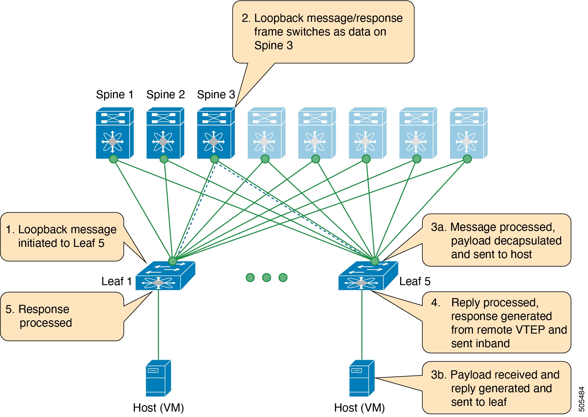
Loopback (Ping) Message

The loopback message (The ping and the loopback messages are the same and they are used interchangeably in this guide) is used for the fault verification. The loopback message utility is used to detect various errors and the path failures. Consider the topology in the following example where there are three core (spine) switches labeled Spine 1, Spine 2, and Spine 3 and five leaf switches connected in a Clos topology. The path of an example loopback message initiated from Leaf 1 for Leaf 5 is displayed when it traverses via Spine 3. When the loopback message initiated by Leaf 1 reaches Spine 3, it forwards it as VXLAN encapsulated data packet based on the outer header. The packet is not sent to the software on Spine 3. On Leaf 3, based on the appropriate loopback message signature, the packet is sent to the software VXLAN OAM module, that in turn, generates a loopback response that is sent back to the originator Leaf 1.

The loopback (ping) message can be destined to VM or to the (VTEP on) leaf switch. This ping message can use different OAM channels. If the ICMP channel is used, the loopback message can reach all the way to the VM if the VM's IP address is specified. If NVO3 draft Tissa channel is used, this loopback message is terminated on the leaf switch that is attached to the VM, as the VMs do not support the NVO3 draft Tissa headers in general. In that case, the leaf switch replies back to this message indicating the reachability of the VM. The ping message supports the following reachability options:

Ping

Check the network reachability (Ping command):

  • From Leaf 1 (VTEP 1) to Leaf 2 (VTEP 2) (ICMP or NVO3 draft Tissa channel)

  • From Leaf 1 (VTEP 1) to VM 2 (host attached to another VTEP) (ICMP or NVO3 draft Tissa channel)

Figure 1. Loopback Message
Figure 2. NVO3 Draft Tissa Ping to Remote VM

Traceroute or Pathtrace Message

The traceroute or pathtrace message is used for the fault isolation. In a VXLAN network, it may be desirable to find the list of switches that are traversed by a frame to reach the destination. When the loopback test from a source switch to a destination switch fails, the next step is to find out the offending switch in the path. The operation of the path trace message begins with the source switch transmitting a VXLAN OAM frame with a TTL value of 1. The next hop switch receives this frame, decrements the TTL, and on finding that the TTL is 0, it transmits a TTL expiry message to the sender switch. The sender switch records this message as an indication of success from the first hop switch. Then the source switch increases the TTL value by one in the next path trace message to find the second hop. At each new transmission, the sequence number in the message is incremented. Each intermediate switch along the path decrements the TTL value by 1 as is the case with regular VXLAN forwarding.

This process continues until a response is received from the destination switch, or the path trace process timeout occurs, or the hop count reaches a maximum configured value. The payload in the VXLAN OAM frames is referred to as the flow entropy. The flow entropy can be populated so as to choose a particular path among multiple ECMP paths between a source and destination switch. The TTL expiry message may also be generated by the intermediate switches for the actual data frames. The same payload of the original path trace request is preserved for the payload of the response.

The traceroute and pathtrace messages are similar, except that traceroute uses the ICMP channel, whereas pathtrace use the NVO3 draft Tissa channel. Pathtrace uses the NVO3 draft Tissa channel, carrying additional diagnostic information, for example, interface load and statistics of the hops taken by these messages. If an intermediate device does not support the NVO3 draft Tissa channel, the pathtrace behaves as a simple traceroute and it provides only the hop information.

Traceroute

Trace the path that is traversed by the packet in the VXLAN overlay using Traceroute command:

  • Traceroute uses the ICMP packets (channel-1), encapsulated in the VXLAN encapsulation to reach the host

Pathtrace

Trace the path that is traversed by the packet in the VXLAN overlay using the NVO3 draft Tissa channel with Pathtrace command:

  • Pathtrace uses special control packets like NVO3 draft Tissa or TISSA (channel-2) to provide additional information regarding the path (for example, ingress interface and egress interface). These packets terminate at VTEP and they does not reach the host. Therefore, only the VTEP responds.

Figure 3. Traceroute Message

VXLAN EVPN Loop Detection and Mitigation Overview

Causes and Impacts of Loop

Loops usually occur in a VXLAN EVPN fabric due to incorrect cabling on the south side (access side) of the fabric. When broadcast packets are injected into a network with a loop, the frame remains bridged in the loop. As more broadcast frames enter the loop, they accumulate and can cause a serious disruption of services.

Guidelines and Limitations for VXLAN NGOAM

VXLAN NGOAM has the following guidelines and limitations:

Supported Platform and Release for VXLAN NGOAM

Supported Release Supported Platform

Configuring VXLAN OAM

Before you begin

As a prerequisite, ensure that the VXLAN configuration is complete.

Procedure

  Command or Action Purpose

Step 1

switch# configure terminal

Enters global configuration mode.

Step 2

switch(config)# feature ngoam

Enters the NGOAM feature.

Step 3

switch(config)# hardware access-list tcam region arp-ether 256 double-wide

For Cisco Nexus 9300 platform switches with Network Forwarding Engine (NFE), configure the TCAM region for ARP-ETHER using this command. This step is essential to program the ACL rule in the hardware and it is a prerequisite before installing the ACL rule.

Note

 
  • Configuring the TCAM region requires the node to be rebooted.

  • This command is not applicable for Cisco Nexus 9300-EX/FX/FX2/GX Series switches.

Step 4

switch(config)# ngoam install acl

Installs the NGOAM Access Control List (ACL).

Step 5

(Optional) bcm-shell module 1 "fp show group 62"

(Optional)

For Cisco Nexus 9300 Series switches with Network Forwarding Engine (NFE), complete this verification step. After entering the command, perform a lookup for entry/eid with data=0x8902 under EtherType.

Example

See the following examples of the configuration topology.

Figure 4. VXLAN Network

VXLAN OAM provides the visibility of the host at the switch level, that allows a leaf to ping the host using the ping nve command.

The following examples display how to ping from Leaf 1 to VM2 via Spine 1 with channel 1 (unique loopback) and with channel 2 (NVO3 Draft Tissa):


switch# ping nve ip 209.165.201.5 vrf vni-31000 source 1.1.1.1 verbose

Codes: '!' - success, 'Q' - request not sent, '.' - timeout,
'D' - Destination Unreachable, 'X' - unknown return code,
'm' - malformed request(parameter problem),
'c' - Corrupted Data/Test, '#' - Duplicate response


Sender handle: 34 
! sport 40673 size 39,Reply from 209.165.201.5,time = 3 ms
! sport 40673 size 39,Reply from 209.165.201.5,time = 1 ms
Success rate is 100 percent (5/5), round-trip min/avg/max = 1/4/18 ms
Total time elapsed 49 ms
                                           <<<<< add space here
switch# ping nve ip unknown vrf vni-31000 payload ip 209.165.201.5 209.165.201.4 payload-end verify-host
<snip>
Sender handle: 34 
!!!!!
Success rate is 100 percent (5/5), round-trip min/avg/max = 1/4/18 ms
Total time elapsed 49 ms

Note


The source ip-address 1.1.1.1 used in the above example is a loopback interface that is configured on Leaf 1 in the same VRF as the destination ip-address. For example, the VRF in this example is vni-31000.


The following example displays how to traceroute from Leaf 1 to VM 2 via Spine 1.


switch# traceroute nve ip 209.165.201.5 vrf vni-31000 source 1.1.1.1 verbose


Codes: '!' - success, 'Q' - request not sent, '.' - timeout,
'D' - Destination Unreachable, 'X' - unknown return code,
'm' - malformed request(parameter problem),
'c' - Corrupted Data/Test, '#' - Duplicate response


Traceroute request to peer ip 209.165.201.4 source ip 209.165.201.2
Sender handle: 36
  1 !Reply from 209.165.201.3,time = 1 ms		
  2 !Reply from 209.165.201.4,time = 2 ms		
  3 !Reply from 209.165.201.5,time = 1 ms


The following example displays how to pathtrace from Leaf 2 to Leaf 1.

switch# pathtrace nve ip 209.165.201.4 vni 31000 verbose

Path trace Request to peer ip 209.165.201.4 source ip 209.165.201.2

Sender handle: 42
TTL			Code		Reply																	IngressI/f				EgressI/f				State 
======================================================================
1     !Reply from 209.165.201.3,  Eth5/5/1      Eth5/5/2     UP/UP
2     !Reply from 209.165.201.4,  Eth1/3	    			Unknown     	UP/DOWN


The following example displays how to MAC ping from Leaf 2 to Leaf 1 using NVO3 draft Tissa channel:

switch# ping nve mac 0050.569a.7418 2901 ethernet 1/51 profile 4 verbose 

Codes: '!' - success, 'Q' - request not sent, '.' - timeout,
'D' - Destination Unreachable, 'X' - unknown return code,
'm' - malformed request(parameter problem),
'c' - Corrupted Data/Test, '#' - Duplicate response

Sender handle: 408
!!!!Success rate is 100 percent (5/5), round-trip min/avg/max = 4/4/5 ms
Total time elapsed 104 ms

switch# show run ngoam
feature ngoam
ngoam profile 4
oam-channel 2
ngoam install acl

The following example displays how to pathtrace based on a payload from Leaf 2 to Leaf 1:


switch# pathtrace nve ip unknown vrf vni-31000 payload mac-addr 0050.569a.d927 0050.569a.a4fa
ip 209.165.201.5 209.165.201.1 port 15334 12769 proto 17 payload-end

Codes: '!' - success, 'Q' - request not sent, '.' - timeout,
'D' - Destination Unreachable, 'X' - unknown return code,
'm' - malformed request(parameter problem),
'c' - Corrupted Data/Test, '#' - Duplicate response

Path trace Request to peer ip 209.165.201.4 source ip 209.165.201.2
Sender handle: 46
TTL Code Reply IngressI/f EgressI/f State
======================================================================
1 !Reply from 209.165.201.3, Eth5/5/1 Eth5/5/2 UP/UP
2 !Reply from 209.165.201.4, Eth1/3 Unknown UP/DOWN

Note


When the total hop count to final destination is more than 5, the path trace default TTL value is 5. Use max-ttl option to finish VXLAN OAM path trace completely.

For example: pathtrace nve ip unknown vrf vrf-vni13001 payload ip 200.1.1.71 200.1.1.23 payload-end verbose max-ttl 10


Configuring NGOAM Profile

Complete the following steps to configure NGOAM profile.

Procedure

  Command or Action Purpose

Step 1

switch(config)# [no] feature ngoam

Enables or disables NGOAM feature

Step 2

switch(config)# [no] ngoam profile <profile-id>

Configures OAM profile. The range for the profile-id is <1 – 1023>. This command does not have a default value. Enters the config-ngoam-profile submode to configure NGOAM specific commands.

Note


All profiles have default values and the show run all CLI command displays them. The default values are not visible through the show run CLI command.

Step 3

switch(config-ng-oam-profile)# ?

Example:


switch(config-ng-oam-profile)# ?
  description  Configure description of the profile
  dot1q        Encapsulation dot1q/bd
  flow         Configure ngoam flow
  hop          Configure ngoam hop count
  interface    Configure ngoam egress interface
  no           Negate a command or set its defaults
  oam-channel  Oam-channel used
  payload      Configure ngoam payload
  sport        Configure ngoam Udp source port range


Displays the options for configuring NGOAM profile.

Example

See the following examples for configuring an NGOAM profile and for configuring NGOAM flow.


switch(config)#
ngoam profile 1
oam-channel 1
flow forward
payload pad 0x2
sport 12345, 54321

switch(config-ngoam-profile)#flow {forward }
Enters config-ngoam-profile-flow submode to configure forward flow entropy specific
information