Configuring FCoE

This chapter contains the following sections:

FCoE Topologies

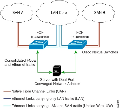
Directly Connected CNA Topology

The Cisco Nexus device can be deployed as a Fibre Channel Forwarder (FCF) as shown in the following figure.

Figure 1. Directly Connected Fibre Channel Forwarder
Directly Connected Fibre Channel Forwarder

The following rules are used to process FIP frames to avoid the FCF being used as a transit between an FCoE node (ENode) and another FCF. These rules also prevent login sessions between ENodes and FCFs in different fabrics.

  • FIP solicitation and login frames received from the CNAs are processed by the FCF and are not forwarded.

  • If an FCF receives solicitations and advertisements from other FCFs over an interface, the following occurs:

    • The frames are ignored and discarded if the FC-MAP value in the frame matches the value of the FCF (the FCF is in the same fabric).

    • The interface is placed in the "FCoE Isolated" state if the FC-MAP value in the FIP frame does not match that of the FCF (the FCF is in a different fabric).

CNAs cannot discover or log in to FCFs that are reachable only through a transit Cisco Nexus FCF. The Cisco Nexus device cannot perform the FCoE transit function between a CNA and another FCF due to hardware limitations.

Because the Cisco Nexus FCF cannot perform the transit FCoE function, you must design your network topology so that the active Spanning Tree Protocol (STP) path of FCoE VLANs is always over the directly connected links between the CNA and the FCF. Make sure that you configure the FCoE VLAN on the directly connected links only.

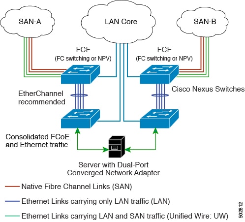
Remotely Connected CNA Topology

The Cisco Nexus device can be deployed as a Fibre Channel Forwarder (FCF) for remotely connected CNAs, but not as a FIP snooping bridge, as shown in the following figure.

Figure 2. Remotely Connected Fibre Channel Forwarder
Remotely Connected Fibre Channel Forwarder

The following rules are used to process FIP frames to avoid the FCF being used as a transit between an ENode and another FCF. These rules also prevent login sessions between ENodes and FCFs in different fabrics.

  • FIP solicitation and login frames received from the CNAs are processed by the FCF and are not forwarded.

  • If an FCF receives solicitations and advertisements from other FCFs over an interface, the following occurs:

    • The frames are ignored and discarded if the FC-MAP value in the frame matches the value of the FCF (the FCF is in the same fabric).

    • The interface is placed in the "FCoE Isolated" state if the FC-MAP value in the FIP frame does not match that of the FCF (the FCF is in a different fabric).

Because the Cisco Nexus FCF cannot perform the transit FCoE function, you must design your network topology so that the active STP path of FCoE VLANs is always over the directly connected links between the CNA and the FCF. Make sure that you configure the FCoE VLAN on the directly connected links only.

FCoE Best Practices

Directly Connected CNA Best Practice

The following figure shows a best practices topology for an access network that is using directly connected CNAs with Cisco Nexus devices.

Figure 3. Directly Connected CNA
Directly Connected CNA

Follow these configuration best practices for the deployment topology in the preceding figure:

  1. You must configure a unique dedicated VLAN at every converged access switch to carry traffic for each Virtual Fabric (VSAN) in the SAN (for example, VLAN 1002 for VSAN 1, VLAN 1003 for VSAN 2, and so on). If you enable Multiple Spanning Tree (MST), you must use a separate MST instance for FCoE VLANs.

  2. You must configure the unified fabric (UF) links as trunk ports. Do not configure the FCoE VLAN as a native VLAN. You must configure all FCoE VLANs as members of the UF links to allow extensions for VF_Port trunking and VSAN management for the virtual Fibre Channel interfaces.


    Note


    A unified wire carries both Ethernet and FCoE traffic.


  3. You must configure the UF links as spanning-tree edge ports.

  4. You must not configure the FCoE VLANs as members of Ethernet links that are not designated to carry FCoE traffic because you want to ensure that the scope of the STP for the FCoE VLANs is limited to UF links only.

  5. If the converged access switches (in the same SAN fabric or in another) need to be connected to each other over Ethernet links for a LAN alternate path, you must explicitly configure such links to exclude all FCoE VLANs from membership. This action ensures that the scope of the STP for the FCoE VLANs is limited to UF links only.

  6. You must use separate FCoE VLANs for FCoE in SAN-A and SAN-B.

Remotely Connected CNA Best Practice

The following figure shows a best practices topology for an access network using remotely connected CNAs with Cisco Nexus devices.

Figure 4. Remotely Connected CNAs
Remotely Connected CNAs

Follow these configuration best practices for the deployment topology in the preceding figure:

  1. You must configure a unique dedicated VLAN at every converged access switch to carry traffic for each Virtual Fabric (VSAN) in the SAN (for example, VLAN 1002 for VSAN 1, VLAN 1003 for VSAN 2, and so on). If you enable MST, you must use a separate MST instance for FCoE VLANs.

  2. You must configure the unified fabric (UF) links as trunk ports. Do not configure the FCoE VLAN as a native VLAN. You must configure all FCoE VLANs as members of the UF links to allow extensions for VF_Port trunking and VSAN management for the virtual Fibre Channel interfaces.


    Note


    A unified fabric link carries both Ethernet and FCoE traffic.


  3. You must configure the CNAs and the blade switches as spanning-tree edge ports.

  4. A blade switch must connect to exactly one Cisco Nexus device converged access switch, preferably over an EtherChannel, to avoid disruption due to STP reconvergence on events such as provisioning new links or blade switches.

  5. You must configure the Cisco Nexus device converged access switch with a better STP priority than the blade switches that are connected to it. This requirement allows you to create an island of FCoE VLANs where the converged access switch is the spanning-tree root and all the blade switches connected to it become downstream nodes.

  6. Do not configure the FCoE VLANs as members of Ethernet links that are not designated to carry FCoE traffic because you want to ensure that the scope of the STP for the FCoE VLANs is limited to UF links only.

  7. If the converged access switches and/or the blade switches need to be connected to each over Ethernet links for the purposes of LAN alternate pathing, you must explicitly configure such links to exclude all FCoE VLANs from membership. This action ensures the scope of the STP for FCoE VLANs is limited to UF links only.

  8. You must use separate FCoE VLANs for FCoE in SAN-A and SAN-B.

Guidelines and Limitations

FC/FCoE has the following guidelines and limitations:

  • Enabling FCoE on VLAN 1 is not supported.

  • Enabling FCoE requires enabling the LLDP feature using feature lldp, as LLDP is not enabled by default.

  • FCOE is not supported with Copper SFPs.

  • Direct connect FCoE (that is, a direct connect to CNAs through a bind interface) is not supported on a port channel of a Cisco Nexus device interface if it is configured to have more than one interface. Direct connect FCoE is supported on port channels with a single link to allow for FCoE from a CNA connected through a vPC with one 10/40 GB link to each upstream switch.

  • Ethernet interfaces used for vFC must have the QOS policy configured manually regardless of default or custom policy defined globally.


Note


For a description of the default quality of service (QoS) policies for FC/FCoE, see the Quality of Service guide for your device. For the Nexus software release that you are using. The available versions of this document can be found at the following URL: https://www.cisco.com/c/en/us/support/switches/nexus-9000-series-switches/products-installation-and-configuration-guides-list.html


Configuring FC/FCoE

Perform TCAM Carving

This section explains how to perform TCAM carving.

SUMMARY STEPS

  1. Perform TCAM carving.
  2. Use the command show hardware access-list tcam region to view the configured TCAM region size.
  3. Save the configuration and use the command reload to reload the switch.

DETAILED STEPS


Step 1

Perform TCAM carving.

Example:


    Switch(config)# hardware access-list tcam region ing-racl 1536
    Switch(config)# hardware access-list tcam region ing-ifacl 256
    Switch(config)# hardware access-list tcam region ing-redirect 256

Step 2

Use the command show hardware access-list tcam region to view the configured TCAM region size.

Example:


  Switch(config)# show hardware access-list tcam region
  Switch(config)# 

Step 3

Save the configuration and use the command reload to reload the switch.

Example:


  Switch(config)# reload
  Switch(config)# 

What to do next

You must reload the switch after carving TCAM

Configuring LLDP

This section explains how to configure LLDP.

SUMMARY STEPS

  1. configure terminal
  2. [no]feature lldp

DETAILED STEPS


Step 1

configure terminal

Enters global configuration mode.

Step 2

[no]feature lldp

Enables or disables LLDP on the device. LLDP is disabled by default.


Configuring Default QoS

There are four types of FCoE default policies: network QoS, output queuing, input queuing, and QoS. You can enable the FCoE default policies by enabling the FCoE feature using the feature-set fcoe command command. The default QoS ingress policy, default-fcoe-in-policy, is implicitly attached to all FC and SAN-port-channel interfaces to enable FC to FCoE traffic; this can be verified by using show interface {fc slot/port | san-port-channel <no>} all command. The default QoS policy uses CoS3 and Q1 for all FC and FCoE traffic.

Configuring User Defined QoS

To use a different queue or CoS value for FCoE traffic, create user-defined policies. The user-defined QoS ingress policy has to be created and attached explicitly to both FC and FCoE interfaces to enable traffic to use a different queue or CoS. User-defined QoS policies must be created and activated for system-wide QoS.


Note


The Ethernet or port-channel interface must be configured with MTU 9216 (or the maximum available MTU size) for supporting FCoE.


The following example demonstrates how to configure and activate user-defined QoS policies that use CoS3 and Q2 for all FC and FCoE traffic.

  • Creating a user-defined network QOS policy:
    
    switch(config)# policy-map type network-qos fcoe_nq
    switch(config-pmap-nqos)# class type network-qos c-nq1
    switch(config-pmap-nqos-c)# mtu 1500
    switch(config-pmap-nqos-c)# class type network-qos c-nq2
    switch(config-pmap-nqos-c)# mtu 9216
    switch(config-pmap-nqos-c)# pause pfc-cos 3 
    switch(config-pmap-nqos-c)# class type network-qos c-nq3
    switch(config-pmap-nqos-c)# mtu 1500
    switch(config-pmap-nqos-c)# class type network-qos c-nq-default
    switch(config-pmap-nqos-c)# mtu 1500
    switch(config-pmap-nqos-c)# exit
    switch(config-pmap-nqos)# exit
    switch(config)#
    
  • Creating a user-defined input queuing policy:

    switch(config)# policy-map type queuing fcoe-in-policy
    switch(config-pmap-que)# class type queuing c-in-q2
    switch(config-pmap-c-que)# bandwidth percent 50
    switch(config-pmap-c-que)# class type queuing c-in-q-default
    switch(config-pmap-c-que)# bandwidth percent 50
    switch(config-pmap-c-que)# exit
    switch(config-pmap-que)# exit
    switch(config)
    
  • Creating a user-defined output queuing policy:

    switch(config)# policy-map type queuing fcoe-out-policy
    switch(config-pmap-que)# class type queuing c-out-q3
    switch(config-pmap-c-que)# priority level 1
    switch(config-pmap-c-que)# class type queuing c-out-q-default
    switch(config-pmap-c-que)# bandwidth remaining percent 50
    switch(config-pmap-c-que)# class type queuing c-out-q1
    switch(config-pmap-c-que)# bandwidth remaining percent 0
    switch(config-pmap-c-que)# class type queuing c-out-q2
    switch(config-pmap-c-que)# bandwidth remaining percent 50
    switch(config-pmap-c-que)# exit
    switch(config-pmap-que)# exit
    switch(config)#
    
    
  • Creating a user-defined QoS input policy:

    
    switch(config)# class-map type qos match-any fcoe
    switch(config-cmap-qos)# match protocol fcoe
    switch(config-cmap-qos)# match cos 3
    switch(config-cmap-qos)# exit
    switch(config)#
    switch(config)# policy-map type qos fcoe_qos_policy
    switch(config-pmap-qos)# class fcoe
    switch(config-pmap-c-qos)# set cos 3
    switch(config-pmap-c-qos)# set qos-group 2
    switch(config-pmap-c-qos)# exit
    switch(config-pmap-qos)# exit
    switch(config)#
    
  • Activating a user-defined system QoS policy:

    switch(config)# system qos 
    switch(config-sys-qos)# service-policy type queuing input fcoe-in-policy 
    switch(config-sys-qos)# service-policy type queuing output fcoe-out-policy 
    switch(config-sys-qos)# service-policy type network-qos fcoe_nq 
    switch(config-sys-qos)# exit 
    switch(config)#
  • Applying a QoS input policy to an FC or FCoE interface:

    
    switch# conf 
    switch(config)# interface {fc <slot>/<port> | ethernet <slot>/<port> | san-port-channel <no> | port-channel <no>}
    switch(config-if)# service-policy type qos input fcoe_qos_policy
  • Removing a QoS input policy from an FC or FCoE interface:

    
    switch# conf 
    switch(config)# interface {fc <slot>/<port> | ethernet <slot>/<port> | san-port-channel <no> | port-channel <no>}
    switch(config-if)# no service-policy type qos input fcoe_qos_policy
  • Verifying a QoS input policy applied to an FC or FCoE interface:

    
    switch# show running-config interface {fc <slot>/<port> | interface <slot>/<port> | san-port-channel <no> | port-channel <no>} all

Note


  • When a user-defined QoS policy is used, the same QoS input policy must be applied to all FC and FCoE interfaces in the switch.

  • Do not configure match protocol fcoe under more than one QoS class map, as FCoE traffic is supported only on a single CoS.


Configuring Traffic Shaping

Traffic shaping is used to control access to available bandwidth and to regulate the flow of traffic in order to avoid congestion that can occur when the sent traffic exceeds the access speed. Because traffic shaping limits the rate of transmission of data, you may use this command only when necessary.

The following example demonstrates how to configure traffic shaper:

  • The following command displays the default system level settings for all FC interfaces:
    
    switch(config)# show running-config all | i i rate
    hardware qos fc rate-shaper  
    switch(config)#
    
  • The following example shows how to configure rate shaper. This command is applied on all FC interfaces:


    Note


    Rarely, you may see input discards on any of the 4G, 8G, 16G, or 32G interfaces. Use the command hardware qos fc rate-shaper [low], to configure the rate shape. Because this is a system level configuration, it will apply to all the FC ports and will reduce the rates for all FC ports. The default option of the command hardware qos fc rate-shaper is applicable to all FC interfaces.


    switch(config)# hardware qos fc rate-shaper low
    switch(config)#  
    switch(config)#end
    

FCoE with vPC Configuration Examples

Figure 5. FCoE Traffic Flow with Host vPC
FCoE Traffic Flow with Enhanced vPC

Note


FCoE VLANs should not be trunked across vPC peer-links.


Note


Only FC uplinks are supported on Cisco Nexus N9K switches (switchmode) that connects to core switches.


The configuration example includes the following parameters:

switchname: tme-switch-1
switchname: tme-switch-2
mgmt ip: 172.25.182.66
mgmt ip: 172.25.182.67

The configuration example includes the following hardware:

  • Emulex CNA or CISCO CNA

  • 2 Cisco Nexus 9000 switches running Cisco NX-OS Release .

The configuration example includes the following considerations and requirements:

  • Generation 2 CNAs that support DCBX are required.

  • Single host CNA port channel connection to a separate switch. FCoE interfaces will not be brought up if the port channel on a single switch contains more than one member port in a port channel or vPC.

  • Cisco NX-OS Release .

Cisco Nexus 9000 Series Switch vPC Configuration Example

This example presumes that the basic configuration has been completed on the switch (for example, IP Address (mgmt0), switchname, and password for the administrator).


Note


The configuration must be done on both peer switches in the vPC topology.


SUMMARY STEPS

  1. feature vpc
  2. vPC domain
  3. vpc peer-link
  4. show vpc peer-keepalive
  5. int po
  6. vpc
  7. show vpc statistics

DETAILED STEPS

  Command or Action Purpose

Step 1

feature vpc

Example:

tme-switch-1# conf t
Enter configuration commands, one per line. End with CNTL/Z.
tme-switch-1(config)# feature vpc
tme-switch-1(config)#
 
tme-switch-2# conf t
Enter configuration commands, one per line. End with CNTL/Z.
tme-switch-2(config)# feature vpc
tme-switch-2(config)#

Enable the vPC feature on both peer switches.

Step 2

vPC domain

Example:

tme-switch-1(config)# vpc domain 2
tme-switch-1(config-vpc-domain)# peer-keepalive destination 192.165.200.229
 
tme-switch-2(config)# vpc domain 2
tme-switch-2(config-vpc-domain)# peer-keepalive destination 192.165.200.230

Configure the vPC domain and peer-keep alive destinations.

Note


In this set up, switch tme-switch-1 has the mgmt IP address of 192.165.200.229 and switch tme-switch-2 has the mgmt IP address of 192.165.200.230.

Step 3

vpc peer-link

Example:

tme-switch-1(config)# int port-channel 1
tme-switch-1(config-if)# vpc peer-link 

Note


The spanning tree port type is changed to network port type on vPC peer-link. This will enable STP Bridge Assurance on vPC peer-link provided that the STP Bridge Assurance (which is enabled by default) is not disabled.


tme-switch-2(config)# int port-channel 1
tme-switch-2(config-if)# vpc peer-link 

Configure the port channel interface that will be used as the vPC peer-link.

Step 4

show vpc peer-keepalive

Example:

tme-switch-1(config)# show vpc peer-keepalive
vPC keep-alive status : peer is alive
--Destination : 172.25.182.167
--Send status : Success
--Receive status : Success
--Last update from peer : (0) seconds, (975) msec
tme-switch-1(config)#
 
tme-switch-2(config)# show vpc peer-keepalive
--PC keep-alive status : peer is alive
--Destination : 172.25.182.166
--Send status : Success
--Receive status : Success
--Last update from peer : (0) seconds, (10336) msec
tme-switch-2(config)# 

Verify that the peer-keepalive can be reached.

Step 5

int po

Example:

tme-switch-1(config-if-range)# int po 1
tme-switch-1(config-if)# switchport mode trunk
tme-switch-1(config-if)# no shut
tme-switch-1(config-if)# exit
tme-switch-1(config)# int eth 1/39-40
tme-switch-1(config-if-range)# switchport mode trunk
tme-switch-1(config-if-range)# channel-group 1
tme-switch-1(config-if-range)# no shut
tme-switch-1(config-if-range)#
 
tme-switch-2(config-if-range)# int po 1
tme-switch-2(config-if)# switchport mode trunk
tme-switch-2(config-if)# no shut
tme-switch-2(config-if)# exit
tme-switch-2(config)# int eth 1/39-40
tme-switch-2(config-if-range)# switchport mode trunk
tme-switch-2(config-if-range)# channel-group 1
tme-switch-2(config-if-range)# no shut
tme-switch-2(config-if-range)#
 
tme-switch-1(config-if-range)# show int po1
port-channel 1 is up
Hardware: Port-Channel, address: 000d.ecde.a92f (bia 000d.ecde.a92f)
MTU 1500 bytes, BW 20000000 Kbit, DLY 10 usec,
reliability 255/255, txload 1/255, rxload 1/255
Encapsulation ARPA
Port mode is trunk
full-duplex, 10 Gb/s
Beacon is turned off
Input flow-control is off, output flow-control is off
Switchport monitor is off
Members in this channel: Eth1/39, Eth1/40
Last clearing of "show interface" counters never
1 minute input rate 1848 bits/sec, 0 packets/sec
1 minute output rate 3488 bits/sec, 3 packets/sec
tme-switch-1(config-if-range)#
 
tme-switch-2(config-if-range)# show int po1
port-channel1 is up
Hardware: Port-Channel, address: 000d.ecdf.5fae (bia 000d.ecdf.5fae) MTU 1500 bytes, BW 20000000 Kbit, DLY 10 usec,
reliability 255/255, txload 1/255, rxload 1/255
Encapsulation ARPA
Port mode is trunk
full-duplex, 10 Gb/s
Beacon is turned off
Input flow-control is off, output flow-control is off
Switchport monitor is off
Members in this channel: Eth1/39, Eth1/40
Last clearing of "show interface" counters never
minute input rate 1848 bits/sec, 0 packets/sec
minute output rate 3488 bits/sec, 3 packets/sec
tme-switch-2(config-if-range)# 

Add member ports to the vpc-peer link port channel and bring up the port channel interface.

Step 6

vpc

Example:
tme-switch-1(config)# int po 11
tme-switch-1(config-if)# vpc 11
tme-switch-1(config-if)# switchport mode trunk
tme-switch-1(config-if)# no shut
tme-switch-1(config-if)# int eth 1/1
tme-switch-1(config-if)# switchport mode trunk
tme-switch-1(config-if)# channel-group 11
tme-switch-1(config-if)# spanning-tree port type edge trunk
tme-switch-1(config-if)#

Warning


Edge port type (portfast) should only be enabled on ports connected to a single host. Connecting some devices such as hubs, concentrators, switches, or bridges to this interface when edge port type (portfast) is enabled, can cause temporary bridging loops. Caution should be used in this type of configuration.

tme-switch-2(config)# int po 11
tme-switch-2(config-if)# vpc 11
tme-switch-2(config-if)# switchport mode trunk
tme-switch-2(config-if)# no shut
tme-switch-2(config-if)# int eth 1/1
tme-switch-2(config-if)# switchport mode trunk
tme-switch-2(config-if)# channel-group 11
tme-switch-2(config-if)# spanning-tree port type edge trunk

Warning


Edge port type (portfast) should only be enabled on ports connected to a single host. Connecting some devices such as hubs, concentrators, switches, or bridges to this interface when edge port type (portfast) is enabled, can cause temporary bridging loops. Caution should be used in this type of configuration.

Create the vPC and add member interfaces.

Note


To run FCoE over a vPC topology, the port channel can only have a sinlge member interface.

Note


The vPC number configured under the port channel interface must match on both Nexus 9000 switches. The port channel interface number does not have to match on both switches.

Step 7

show vpc statistics

Example:
tme-switch-1(config-if)# show vpc statistics vpc 11
port-channel11 is up
vPC Status: Up, vPC number: 11
Hardware: Port-Channel, address: 000d.ecde.a908 (bia 000d.ecde.a908)
MTU 1500 bytes, BW 10000000 Kbit, DLY 10 usec,
reliability 255/255, txload 1/255, rxload 1/255
Encapsulation ARPA
Port mode is trunk
full-duplex, 10 Gb/s
Beacon is turned off
Input flow-control is off, output flow-control is off
Switchport monitor is off
Members in this channel: Eth1/1
Last clearing of "show interface" counters never
minute input rate 4968 bits/sec, 8 packets/sec
minute output rate 792 bits/sec, 1 packets/sec
tme-switch-1(config-if)#
 
tme-switch-2(config-if)# show vpc statistics vpc 11
port-channel11 is up
vPC Status: Up, vPC number: 11
Hardware: Port-Channel, address: 000d.ecdf.5fae (bia 000d.ecdf.5fae)
MTU 1500 bytes, BW 10000000 Kbit, DLY 10 usec,
reliability 255/255, txload 1/255, rxload 1/255
Encapsulation ARPA
Port mode is trunk
full-duplex, 10 Gb/s
Beacon is turned off
Input flow-control is off, output flow-control is off
Switchport monitor is off
Members in this channel: Eth1/1
Last clearing of "show interface" counters never
minute input rate 4968 bits/sec, 8 packets/sec
minute output rate 792 bits/sec, 1 packets/sec
tme-switch-1(config-if)#

Verify that the vPC interfaces are up and operational.

Cisco Nexus 9000 Series Switch FCoE Configuration Example

After setting up vPC between the two Nexus 9000 switches, you can configure the FCoE topology. This procedure presumes that basic configuration has been executed on the Nexus 9000 switch that will provide IP Address (mgmt0), switch name, password for admin, etc. and that the vPC configuration has been completed as outlined in the previous section. The following steps will walk through the basic FCoE configuration necessary to set up an FCoE topology in conjunction with the vPC topology.

SUMMARY STEPS

  1. install feature-set fcoe
  2. feature-set fcoe
  3. vsan database
  4. interface port-channel
  5. int vfc
  6. show int brief
  7. show flogi database
  8. show vpc statistics

DETAILED STEPS

  Command or Action Purpose

Step 1

install feature-set fcoe

Install FCoE feature.

Step 2

feature-set fcoe

Example:

tme-switch-1(config)# feature-set fcoe
Please configure the following for fcoe to be fully functional:
- hardware access-list tcam region ing-racl TCAM size
- hardware access-list tcam region ing-ifacl TCAM size
- hardware access-list tcam region ing-redirect TCAM size
tme-switch-1(config)#

tme-switch-2(config)# feature-set fcoe
Please configure the following for fcoe to be fully functional:
- hardware access-list tcam region ing-racl TCAM size
- hardware access-list tcam region ing-ifacl TCAM size
- hardware access-list tcam region ing-redirect TCAM size
tme-switch-2(config)#

Enable FCoE on the Cisco Nexus 9000 switch.

Note


This can take a few moments to complete. You must ensure to complete the TCAM carving before doing this step. After completing the TCAM carving, you must reload the switch.

Step 3

vsan database

Example:
tme-switch-1(config)# vsan database
tme-switch-1(config-vsan-db)# vsan 100
tme-switch-1(config-vsan-db)# exit
tme-switch-1(config)# vlan 100
tme-switch-1(config-vlan)# fcoe vsan 100
tme-switch-1(config-vlan)# show vlan fcoe
VLAN VSAN Status
-------- -------- --------
100 100 Operational
tme-switch-1(config-vlan)#
 
tme-switch-2(config)# vsan database
tme-switch-2(config-vsan-db)# vsan 101
tme-switch-2(config-vsan-db)# exit
tme-switch-2(config)# vlan 101
tme-switch-2(config-vlan)# fcoe vsan 101
tme-switch-2(config-vlan)# show vlan fcoe
VLAN VSAN Status
-------- -------- --------
101 101 Operational
tme-switch-2(config)#

Create a VSAN and map it to a VLAN that has been designated to carry FCoE traffic.

Note


VLAN and VSAN numbers are not required to be the same.

Step 4

interface port-channel

Example:

tme-switch-1(config)# interface port-channel 11
tme-switch-1(config-if)# switchport trunk allowed vlan 1, 100
tme-switch-1(config-if)# mtu 9216
tme-switch-1(config-if)# service-policy type qos input default-fcoe-in-policy
tme-switch-1(config-if)# show int trunk
------------------------------------------------------------------
Port Native Status Port
------------------------------------------------------------------
Eth1/1 1 trnk-bndl Po11
Eth1/39 1 trnk-bndl Po1
Eth1/40 1 trnk-bndl Po1
Po1 1 trunking --
Po11 1 trunking --
 
------------------------------------------------------------------
Port Vlans Allowed on Trunk
------------------------------------------------------------------
Eth1/1 1,100
Eth1/39 1-3967,4048-4093
Eth1/40 1-3967,4048-4093
Po1 1-3967,4048-4093
Po11 1,100
 
------------------------------------------------------------------
Port Vlans Err-disabled on Trunk
------------------------------------------------------------------
Eth1/1 none
Eth1/39 100
Eth1/40 100
Po1 100
Po11 none
 
------------------------------------------------------------------
Port STP Forwarding
------------------------------------------------------------------
Eth1/1 none
Eth1/39 none
Eth1/40 none
Po1 1
Po11 1,100
tme-switch-1(config-if)#
 
tme-switch-2(config)# int po 11
tme-switch-2(config-if)# switchport trunk allowed vlan 1, 101
tme-switch-1(config-if)# mtu 9216
tme-switch-1(config-if)# service-policy type qos input default-fcoe-in-policy
tme-switch-2(config-if)# show int trunk
------------------------------------------------------------------
Port Native Status Port
------------------------------------------------------------------
Eth1/1 1 trnk-bndl Po11
Eth1/39 1 trnk-bndl Po1
Eth1/40 1 trnk-bndl Po1
Po1 1 trunking --
Po11 1 trunking --
 
------------------------------------------------------------------
Port Vlans Allowed on Trunk
------------------------------------------------------------------
Eth1/1 1,101
Eth1/39 1-3967,4048-4093
Eth1/40 1-3967,4048-4093
Po1 1-3967,4048-4093
Po11 1,101
 
------------------------------------------------------------------
Port Vlans Err-disabled on Trunk
------------------------------------------------------------------
Eth1/1 none
Eth1/39 101
Eth1/40 101
Po1 101
Po11 none
 
------------------------------------------------------------------
Port STP Forwarding
------------------------------------------------------------------
Eth1/1 none
Eth1/39 none
Eth1/40 none
Po1 1
Po11 1,101
tme-switch-2(config-if)#

Configure the VLANs that are allowed to transverse the vPC links.

Step 5

int vfc

Example:

tme-switch-1(config)# int vfc 1
tme-switch-1(config-if)# bind interface po11
tme-switch-1(config-if)# no shut
tme-switch-1(config-if)#
 
tme-switch-2(config)# int vfc 1
tme-switch-2(config-if)# bind interface po11
tme-switch-2(config-if)# no shut
tme-switch-2(config-if)#
 
tme-switch-1(config)# vsan database
tme-switch-1(config-vsan-db)# vsan 100 interface vfc 1
tme-switch-1(config)# show vsan membership
vsan 1 interfaces:
fc2/1 fc2/2 fc2/3 fc2/4
fc2/5 fc2/6 fc2/7 fc2/8
 
vsan 100 interfaces:
vfc1
 
vsan 4079(evfp_isolated_vsan) interfaces:
 
vsan 4094(isolated_vsan) interfaces:
tme-switch-1(config)#
 
tme-switch-2(config)# vsan database
tme-switch-2(config-vsan-db)# vsan 101 interface vfc 1
tme-switch-2(config)# show vsan membership
vsan 1 interfaces:
fc2/1 fc2/2 fc2/3 fc2/4
fc2/5 fc2/6 fc2/7 fc2/8
 
vsan 101 interfaces:
vfc1
 
vsan 4079(evfp_isolated_vsan) interfaces:
 
vsan 4094(isolated_vsan) interfaces:
tme-switch-2(config)# 

Create a virtual Fibre Channel interface (vfc) and add it to the VSAN that was created in the previous step.

Step 6

show int brief

Example:

tme-switch-1(config-if)# show int brief
------------------------------------------------------------------
Ethernet VLAN Type Mode Status Reason Speed
------------------------------------------------------------------
Eth1/1 1 eth trunk up none 10G(D)
Eth1/2 1 eth access up none 10G(D)
Eth1/38 1 eth access down SFP not inserted 10G(D)
Eth1/39 1 eth trunk up none 10G(D)
Eth1/40 1 eth trunk up none 10G(D)
 
------------------------------------------------------------------
Port-channel VLAN Type Mode Status Reason Speed
------------------------------------------------------------------
Po1 1 eth trunk up none a-10G(D) none
Po11 1 eth trunk up none a-10G(D) none
 
------------------------------------------------------------------
Port VRF Status IP Address Speed MTU
------------------------------------------------------------------
mgmt0 -- up 172.25.182.166 1000 1500
 
------------------------------------------------------------------
Interface Vsan Admin Admin Status SFP Oper Oper Port
------------------------------------------------------------------
vfc1 100 F on up -- F auto --
tme-switch-1(config-if)#
 
tme-switch-2(config-if)# show int brief
------------------------------------------------------------------
Ethernet VLAN Type Mode Status Reason Speed Port
------------------------------------------------------------------
Eth1/1 1 eth trunk up none 10G(D) 11
Eth1/2 1 eth access up none 10G(D) --
Eth1/38 1 eth access down SFP not inserted 10G(D) --
Eth1/39 1 eth trunk up none 10G(D) 1
Eth1/40 1 eth trunk up none 10G(D) 1
 
------------------------------------------------------------------
Port-channel VLAN Type Mode Status Reason Speed Protocol
------------------------------------------------------------------
Po1 1 eth trunk up none a-10G(D) none
Po11 1 eth trunk up none a-10G(D) none
 
------------------------------------------------------------------
Port VRF Status IP Address Speed MTU
------------------------------------------------------------------
mgmt0 -- up 172.25.182.167 1000 1500
 
------------------------------------------------------------------
Interface Vsan Admin Admin Status SFP Oper Oper
------------------------------------------------------------------
vfc1 101 F on up -- F auto --
tme-switch-2(config-if)#
 

Verify that the vfc is up and operational:

Step 7

show flogi database

Example:
tme-switch-1# show flogi database
------------------------------------------------------------------
INTERFACE VSAN FCID PORT NAME NODE NAME
-----------------------------------------------------------------------
vfc1 100 0x540000 21:00:00:c0:dd:11:2a:01 20:00:00:c0:dd:11:2a:01
 
Total number of flogi = 1.
tme-switch-2# show flogi database
-----------------------------------------------------------------------
INTERFACE VSAN FCID PORT NAME NODE NAME
------------------------------------------------------------------------
vfc1 101 0x540000 21:00:00:c0:dd:11:2a:01 20:00:00:c0:dd:11:2a:01
 
Total number of flogi = 1.

Verify that the virtual Fibre Channel interface has logged into the fabric.

Step 8

show vpc statistics

Example:
tme-switch-1(config-if)# show vpc statistics vpc 11
port-channel11 is up
vPC Status: Up, vPC number: 11
Hardware: Port-Channel, address: 000d.ecde.a908 (bia 000d.ecde.a908)
MTU 1500 bytes, BW 10000000 Kbit, DLY 10 usec,
reliability 255/255, txload 1/255, rxload 1/255
Encapsulation ARPA
Port mode is trunk
full-duplex, 10 Gb/s
Beacon is turned off
Input flow-control is off, output flow-control is off
Switchport monitor is off
Members in this channel: Eth1/1
Last clearing of "show interface" counters never
1 minute input rate 4968 bits/sec, 8 packets/sec
1 minute output rate 792 bits/sec, 1 packets/sec
 
tme-switch-2(config-if)# show vpc statistics vpc 11
port-channel11 is up
vPC Status: Up, vPC number: 11
Hardware: Port-Channel, address: 000d.ecdf.5fae (bia 000d.ecdf.5fae)
MTU 1500 bytes, BW 10000000 Kbit, DLY 10 usec,
reliability 255/255, txload 1/255, rxload 1/255
Encapsulation ARPA
Port mode is trunk
full-duplex, 10 Gb/s
Beacon is turned off
Input flow-control is off, output flow-control is off
Switchport monitor is off
Members in this channel: Eth1/1
Last clearing of "show interface" counters never
1 minute input rate 4968 bits/sec, 8 packets/sec
1 minute output rate 792 bits/sec, 1 packets/sec
 

Verify that the vPC is up and operational.