- Preface
- Introduction to Cisco Data Center Network Manager
- Cisco DCNM User Roles
- Device Pack for Cisco DCNM
- Cisco DCNM Web Client
- Media Controller
- Configuring DCNM Native High Availability
- Cisco DCNM-SAN Overview
- Configuring Cisco DCNM-SAN Server
- Configuring Authentication in Cisco DCNM-SAN
- Configuring Cisco DCNM-SAN Client
- Device Manager
- Configuring Performance Manager
- Monitoring the Network
- Monitoring Performance
- Vacuum and Autovacuum Postgres Databases
- DCNM-SAN Event Management
- Vcenter Plugin
- Interface Nonoperational Reason Codes
Device Manager
This chapter contains descriptions and instructions for using the Device Manager. This chapter contains the following sections:
Information About Device Manager
Device Manager provides a graphical representation of a Cisco MDS 9000 Family switch chassis, a Cisco Nexus 5000 Series switch chassis, or a Cisco Nexus 7000 Series switch chassis including the installed switching modules, the supervisor modules, the status of each port within each module, the power supplies, and the fan assemblies.

Note![]() Device Manager support for Cisco Nexus 7000 Series switches is only for FCoE. Non-FCoE modules appear as Unsupported Card.
Device Manager support for Cisco Nexus 7000 Series switches is only for FCoE. Non-FCoE modules appear as Unsupported Card.
The tables in the DCNM-SAN Information pane basically correspond to the dialog boxes that appear in Device Manager. However, while DCNM-SAN tables show values for one or more switches, a Device Manager dialog box shows values for a single switch. Also, Device Manager provides more detailed information for verifying or troubleshooting device-specific configuration than DCNM-SAN.
Device Manager Release 4.2 and later provides enhanced security using multiple perspectives (simple and advanced) allowing role based-access to its features. The Device Manager perspective filters out menu items that are not relevant to the user. Users with server admin role, can only access a subset of the fabric related features. The server admin role will not be able to manage Device Manager users or connected clients.
Device Manager Release 5.0 and later supports all the software features that are offered by Cisco NX-OS for managing Cisco MDS 9148 and 9124 Multilayer Fabric switches. Cisco MDS 9148 Multilayer Fabric Switch is a 48-port (1/2/4/8G) FC 1RU switch based on the Sabre ASIC andCisco MDS 9124 Multilayer Fabric switch is a 1/2/4/8G switch module for HP BladeServer based on the Sabre ASIC. Device Manager and DCNM-SAN allow you to discover, display, configure, monitor and service both these new switches. Device Manager also supports the following Cisco Nexus 2000 Series Fabric Extenders on a Cisco Nexus 5000 Series switch that runs Cisco NX-OS Release 5.0(1):
- Cisco Nexus 2148T Fabric Extender—It has four 10-Gigabit Ethernet fabric interfaces for its uplink connection to the parent Cisco Nexus 5000 Series switch and eight 1-Gigabit Ethernet or 10-Gigabit Ethernet host interfaces for its downlink connection to servers or hosts.
- Cisco Nexus 2232PP Fabric Extender—It has eight 10-Gigabit Ethernet fabric interfaces with SFP+ interface adapters for its uplink connection to the parent Cisco Nexus 5000 Series switch and 32 10-Gigabit Ethernet fabric interfaces with SFP+ interface adapters for its downlink connection to servers or hosts.
- Cisco Nexus 2248TP Fabric Extender—It has four 10-Gigabit Ethernet fabric interfaces with small form-factor pluggable (SFP+) interface adapters for its uplink connection to the parent Cisco Nexus 5000 Series switch and 48 1000BASE-T (1-Gigabit) Ethernet host interfaces for its downlink connection to servers or hosts.
Device Manager allows you to discover and display these Fabric Extenders. Cisco Device Manager and the Cisco DCNM-SAN client support provisioning and monitoring of the 48-port 8-Gbps Advanced Fibre Channel switching module (DS-X9248-256K9) and the 32-port 8-Gbps Advanced Fibre Channel switching module (DS-X9232-256K9).
Device Manager Features
Device Manager provides two views: Device View and Summary View. Use Summary View to monitor interfaces on the switch. Use Device View to perform switch-level configurations including the following:
- Configure virtual Fibre Channel interfaces.
- Configure Fibre Channel over Ethernet (FCoE).
- Configure zones for multiple VSANs.
- Manage ports, PortChannels, and trunking.
- Manage SNMPv3 security access to switches.
- Manage CLI security access to the switch.
- Manage alarms, events, and notifications.
- Save and copy configuration files and software image.
- View hardware configuration.
- View chassis, module, port status, and statistics.
Using Device Manager Interface
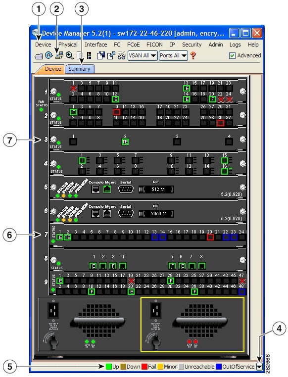
This section describes the Device Manager interface as shown in Figure 11-1.
Figure 11-1 Device Manager, Device Tab
|
|
|
||
|
|
|
||
|
|
|
||
|
|
|
Menu Bar
The menu bar at the top of the Device Manager main window provides options for managing and troubleshooting a single switch. The menu bar provides the following options:
- Device—Opens an instance of Device Manager, sets management preferences, sets the page layout, opens a Telnet/SSH session with the current switch, exports a device image, and closes the Device Manager application.
- Physical—Allows you to view and manage inventory, modules, temperature sensors, power supplies, fans, and the entire system.
- Interface—Allows you to configure and manage PortChannels, as well as Fibre Channel, Ethernet, iSCSI, and FICON ports. Also provides diagnostic, management and monitoring capabilities, as well as SPAN and port tracking.
Note![]() The Interface > Port Channels menu option does not appear if the Cisco Nexus 5000 Series switch is in NPV mode and runs a Cisco NX-OS release prior to 4.2(1).
The Interface > Port Channels menu option does not appear if the Cisco Nexus 5000 Series switch is in NPV mode and runs a Cisco NX-OS release prior to 4.2(1).
- FC—Allows you to configure and manage VSAN, domain, and name server characteristics. Also provides advanced configuration capabilities.
- FCoE—Allows you to configure the FCoE parameters and map VSANs to VLANs on a Cisco Nexus 5000 Series switch.
Note![]() The FCoE menu option appears only if the Cisco Nexus 5000 Series switch runs Cisco NX-OS Release 4.0(1a) or later releases.
The FCoE menu option appears only if the Cisco Nexus 5000 Series switch runs Cisco NX-OS Release 4.0(1a) or later releases.
- FICON—Allows you to configure and manage FICON VSANs, configure RLIR ERL information, swap selected FICON ports, and view FICON port numbers.
- IP—Allows you to configure and manage the following types of information: FCIP, iSCSI, iSNS, routes, VRRP, and CDP.
- Security—Allows you to configure and manage FCSP, port security, iSCSI security, SNMP security, common roles, SSH, AAA, and IP ACLs.
- Admin—Allows you to save, copy, edit, and erase the switch configuration, monitor events, manipulate Flash files, manage licenses, configure NTP, use CFS, and reset the switch. Also enables you to use the show tech support, show cores, and show image commands.
- Logs—Shows the various logs: message, hardware, events, and accounting. Also displays FICON link incidents, and allows you to configure the syslog setup.
- Help—Displays online help topics for specific dialog boxes in the Information pane.
Toolbar Icons
The Device Manager toolbar provides quick access to many Device Manager features. Once the icon is selected, a dialog box may open that allows configuration of the feature. The toolbar provides the main Device and Summary View icons as shown in Table 11-1 .
 Open Device
 Refresh Display
 Command-Line Interface
 Configure Selected
 SysLog
 VSANs
VSANs Save Configuration
 Copy
Copy  Toggle FICON/Interface Port Labels
 Select VSAN
 Help
HelpDialog Boxes
If a toolbar icon is selected, a dialog box may open that allows configuration of the selected feature. The dialog box may include table manipulation icons. See the “Information Pane” for descriptions of these icons.
Tabs
Click the Device tab on the Device Manager main window to see a graphical representation of the switch chassis and components.
Note![]() The Device view also shows the switch chassis information of the Cisco Nexus 2000 Series Fabric Extenders (FEXs) that are connected to a Cisco Nexus 5000 Series switch that runs Cisco NX-OS Release 5.0(1).
The Device view also shows the switch chassis information of the Cisco Nexus 2000 Series Fabric Extenders (FEXs) that are connected to a Cisco Nexus 5000 Series switch that runs Cisco NX-OS Release 5.0(1).
Click the Summary tab on the Device Manager main window to see a summary of active interfaces on a single switch, as well as Fibre Channel and IP neighbor devices. The Summary View also displays port speed, link utilization, and other traffic statistics. There are two buttons in the upper left corner of the Summary View tab used to monitor traffic. To monitor traffic for selected objects, click the Monitor Selected Interface Traffic Util% button. To display detailed statistics for selected objects, click the Monitor Selected Interface Traffic Details button. You can set the poll interval, the type or Rx/Tx display, and the thresholds.
Note![]() The Summary tab does not display the utilization statistics (Util%) of virtual Fibre Channel interfaces for Cisco Nexus 5000 Series switches that run Cisco NX-OS Release 4.2.
The Summary tab does not display the utilization statistics (Util%) of virtual Fibre Channel interfaces for Cisco Nexus 5000 Series switches that run Cisco NX-OS Release 4.2.
Legend
The legend at the bottom right of the Device Manager indicates port status, as follows:
- Green—The port is up.
- Brown—The port is administratively down.
- Red cross—The port is down or has failed as a result of either hardware failure, loopback Diagnostic failure, or link failure.
- Red square—The port is down or has failed as a result of failure other than described for red cross.
- Amber—The port has a minor fault condition as a result of either signal loss, synchronization loss, credit loss, LIP F8 receiver failure, non operational sequence receiver, or off-line sequence receiver failure.
- Gray—The port is unreachable.
- Blue—The port is out of service.
Supervisor and Switching Modules
In the Device View, you can right-click an object and get information on it, or configure it. If you right-click a module, the menu shows the module number and gives you the option to configure or reset the module. If you right-click a port, the menu shows the port number and gives you the option to configure, monitor, enable/disable, set beacon mode, or perform diagnostics on the port.

Tip![]() You can select multiple ports in Device Manager and apply options to all the selected ports at one time. Either select the ports by clicking the mouse and dragging it around them, or hold down the Control key and click each port.
You can select multiple ports in Device Manager and apply options to all the selected ports at one time. Either select the ports by clicking the mouse and dragging it around them, or hold down the Control key and click each port.
To enable or disable a port, right-click the port and click Enable or Disable from the pop-up menu. To enable or disable multiple ports, drag the mouse to select the ports and then right-click the selected ports. Then click Enable or Disable from the pop-up menu.
To manage trunking on one or more ports, right-click the ports and click Configure. In the dialog box that appears, right-click the current value in the Trunk column and click nonTrunk, trunk, or auto from the pull-down list.
To create PortChannels using Device Manager, click PortChannels from the Interface menu.
Note![]() To create a PortChannel, all the ports on both ends of the link must have the same port speed, trunking type, and administrative state.
To create a PortChannel, all the ports on both ends of the link must have the same port speed, trunking type, and administrative state.
Context Menus
Context menus are available in both Device Manager views by right-clicking a device or table.
- Device—Right-click a system, module, or power supply to bring up a menu that gives you the option to configure or reset the device.
- Port— Right-click a port to bring up a menu that shows you the number of the port you have clicked, and to give you the option to configure, monitor, enable, disable, set beacon mode, or perform diagnostics on the port.
Launching Device Manager
To launch Device Manager from your desktop, double-click the Device Manager icon and follow the instructions described in the Cisco DCNM Installation and Licensing Guide.
DETAILED STEPS
Step 1![]() You can choose one of the following three steps
You can choose one of the following three steps
a.![]() Right-click the switch you want to manage on the Fabric pane map and choose Device Manager from the menu that appears.
Right-click the switch you want to manage on the Fabric pane map and choose Device Manager from the menu that appears.
b.![]() Double-click a switch in the Fabric pane map.
Double-click a switch in the Fabric pane map.
c.![]() Select a switch in the Fabric pane map and choose Tools > Device Manager.
Select a switch in the Fabric pane map and choose Tools > Device Manager.
You see the Device Manager open dialog box as shown in Figure 11-2
Figure 11-2 Device Manager: Open Dialog Box
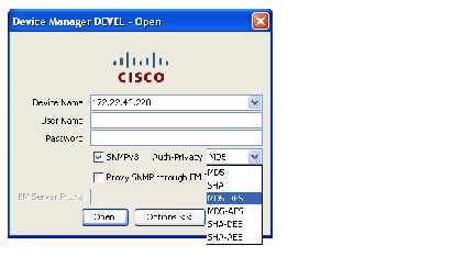
Step 2![]() Enter the IP adress of the device.
Enter the IP adress of the device.
Step 3![]() Enter the user name and password.
Enter the user name and password.
Step 4![]() Check the Proxy SNMP through FMS check box if you want Device Manager Client to use a TCP-based proxy server.
Check the Proxy SNMP through FMS check box if you want Device Manager Client to use a TCP-based proxy server.
Step 5![]() Choose the Auth-Privacy option according to the privacy protocol you have configured on your switch:
Choose the Auth-Privacy option according to the privacy protocol you have configured on your switch:
a.![]() If you have not configured the switch with a privacy protocol, then choose Auth-Privacy option MD5 (no privacy).
If you have not configured the switch with a privacy protocol, then choose Auth-Privacy option MD5 (no privacy).
b.![]() If you have configured the switch with your privacy protocol, choose your Auth-Privacy choice.
If you have configured the switch with your privacy protocol, choose your Auth-Privacy choice.
Step 6![]() Click Open to open the Device Manager.
Click Open to open the Device Manager.
Setting Device Manager Preferences
To set your preferences for the behavior of the Device Manager application, choose Device > Preferences from the Device menu. You can set the following preferences:
- Retry Requests x Time(s) After x sec Timeout —Allows you to set the retry request values. The default settings are 1 time after a 5-second timeout.
- Enable Status Polling Every x secs —Allows you to set the status polling value. The default setting is enabled (checked) with a time of 40 seconds.
- Trace SNMP Packets in Message Lo g—Allows you to set whether Device Manager traces SNMP packets and logs the trace. The default setting is disabled (unchecked).
- Register for Events After Open, Listen on Port 116 3—Allows you to register this switch so that events are logged once you open Device Manager. The default setting is enabled (checked).
- Show WorldWideName (WWN) Vendor —Displays the world wide name vendor name in any table or listing displayed by Device Manager. If Prepend is checked, the name is displayed in front of the IP address of the switch. If Replace is checked, the name is displayed instead of the IP address. The default setting is enabled (checked) with the Prepend option.
- Show Timestamps as Date/Time —Displays timestamps in the date/time format. If this preference is not checked, timestamps are displayed as elapsed time. The default setting is enabled (checked).
- Telnet Path —Sets the path for the telnet.exe file on your system. The default is telnet.exe, but you need to browse for the correct location.
Note![]() If you browse for a path or enter a path and you have a space in the pathname (for example, c:\program files\telnet.exe, then the path will not work. To get the path to work, manually place quotes around it (for example, "c:\program files\telnet.exe").
If you browse for a path or enter a path and you have a space in the pathname (for example, c:\program files\telnet.exe, then the path will not work. To get the path to work, manually place quotes around it (for example, "c:\program files\telnet.exe").
- Use Secure Shell Instead of Telnet —Specifies whether to use SSH or Telnet when using the CLI to communicate with the switch. If enabled, you must specify the path to your SSH application. The default setting is disabled.
- CLI Session Timeout x secs (0= disable) —Specifies the timeout interval for a CLI session. Enter 0 to disable (no timeout value). The default setting is 30 seconds.
- Show Tooltips in Physical View —Determines whether tooltips are displayed in Physical (Device) View. The default setting is enabled (checked).
- Label Physical View Ports With: —Specifies the type of label to assign to the ports when you are in Physical (Device) View. The options are FICON and Interface. The default setting is Interface.
- Export Table —Specifies the type of file that is created when you export a table using Device Manager. The options are Tab-Delimited or XML. The default setting is Tab-Delimited.
 Feedback