Cisco DCNM in Clustered Mode
By default, the clustered mode if not enabled on the Cisco DCNM deployments. Enable the cluster mode after you deploy the Cisco DCNM Server. In a clustered mode, the Cisco DCNM Server with more compute nodes provides an architecture to expand resources, as you deploy more applications.
Compute nodes are scale out application hosting nodes that run resource-intensive services to provide services to the larger Fabric. When compute nodes are added, all services that are containers, run only on these nodes. This includes Config Compliance, Endpoint Locator, and Virtual Machine Manager. The Elasticsearch time series database for these features runs on compute nodes in clustered mode. In the clustered mode deployment, the DCNM Servers do not run containerized applications. All applications that work in unclustered mode works in the clustered mode, also.
 Note |
The clustered mode is not supported on Cisco DCNM for Media Controller deployment. |
From Cisco DCNM Release 11.1(1), in a Native HA setup, 80 switches with Endpoint Locator, Virtual Machine Manager, config compliance are validated in the unclustered mode. For a network exceeding 80 switches, with these features in a given Cisco DCNM instance (maximum qualified scale is 256 switches), we recommend that you enable clustered mode.
While the Cisco DCNM core functionalities only run on the Native HA nodes, addition of compute nodes beyond 80 switches is to build a scale-out model for Cisco DCNM and related services.
From Release 11.2(1), you can configure IPv6 address for Network Management for compute clusters. However, DCNM does not support IPv6-address for containers, and must connect to DCNM using only IPv4 address only.
For best practices and recommended deployments for IP address configurations of all interfaces of the Cisco DCNM and Compute nodes, see Best Practices for Deploying Cisco DCNM and Computes in Cisco DCNM Installation Guide, for your deployment type.
Requirements for Cisco DCNM Clustered Mode
Note |
We recommend that you install the Cisco DCNM in the Native HA mode. |
Cisco DCNM LAN Deployment Without Network Insights (NI)
| Node | CPU Deployment Mode | CPU | Memory | Storage | Network |
|---|---|---|---|---|---|
| DCNM | OVA/ISO | 16 vCPUs | 32G | 500G HDD | 3xNIC |
| Computes | NA | — | — | — | — |
| Node | CPU Deployment Mode | CPU | Memory | Storage | Network |
|---|---|---|---|---|---|
| DCNM | OVA/ISO | 16 vCPUs | 32G | 500G HDD | 3xNIC |
| Computes x 3 | OVA/ISO | 16 vCPUs | 64G | 500G HDD | 3xNIC |
Cisco DCNM LAN Deployment with NIA and NIR Software Telemetry
Note |
We recommend that you install the Cisco DCNM in the Native HA mode. |
| Node | CPU Deployment Mode | CPU | Memory | Storage | Network |
|---|---|---|---|---|---|
| DCNM | OVA/ISO | 16 vCPUs | 32G | 500G HDD | 3xNIC |
| Computes x 3 | OVA/ISO | 16 vCPUs | 64G | 500G HDD | 3xNIC |
| Node | CPU Deployment Mode | CPU | Memory | Storage | Network |
|---|---|---|---|---|---|
| DCNM | OVA/ISO | 16 vCPUs | 32G | 500G HDD | 3xNIC |
| Computes x 3 | ISO | 32 vCPUs | 256G | 2.4-TB HDD | 3xNIC1 |
Subnet Requirements
In general, Eth0 of the Cisco DCNM server is used for Management, Eth1 is used to connect Cisco DCNM Out-Of-Band with switch management, and eth2 is used for In-Band front panel connectivity of Cisco DCNM. The same concept extends into compute nodes as well. Some services in clustered mode have other requirements. Some services require a switch to reach into Cisco DCNM. For example, Route Reflector to Endpoint Locator connection or switch streaming telemetry into the Telemetry receiver service of the application require a switch to reach DCNM. This IP address needs to remain sticky during all failure scenarios. For this purpose, an IP pool must be provided to Cisco DCNM at the time of cluster configuration for both out-of-band and In-Band subnets.
Telemetry NTP Requirements
For telemetry to work correctly, the Cisco Nexus 9000 switches and Cisco DCNM must be time that is synchronized. Cisco DCNM telemetry manager does the required NTP configuration as part of enablement. If there is a use-case to change the NTP server configuration manually on the switches ensure that the DCNM and the switches are time synchronized, always. To set up telemetry network configuration, see .
Installing a Cisco DCNM Compute
Note |
With Native HA installations, ensure that the HA status is OK before DCNM is converted to cluster mode. |
A Cisco DCNM Compute can be installed using an ISO or OVA of a regular Cisco DCNM image. It can be deployed directly on a bare metal using an ISO or a VM using the OVA. After you deploy Cisco DCNM, using the DCNM web installer, choose Compute as the install mode for Cisco DCNM Compute nodes. On a Compute VM, you will not find DCNM processes or postgres database; it runs a minimum set of services that are required to provision and monitor applications.
Networking Policies for OVA Installation
For each compute OVA installation, ensure that the following networking policies are applied for the corresponding vSwitches of host:
-
Log on to the vCenter.
-
Click on the Host on which the computes OVA is running.
-
Click Configuration > Networking.
-
Right click on the port groups corresponding to the eth1 and eth2, and select Edit Settings.
The VM Network - Edit Settings is displayed.
-
In Security settings, for Promiscuous mode, select Accepted.
-
If a DVS Port-group is attached to the compute VM, configure these settings on the vCenter > Networking > Port-Group. If a normal vSwitch port-group is used, configure these settings on Configuration > Networking > port-group on each of the Compute's hosts.
Figure 1. Security Settings for vSwitch Port-Group 
Figure 2. Security Settings for DVSwitch Port-Group 
Note |
Ensure that you repeat this procedure on all the hosts, where a Compute OVA is running. |
Adding Computes into the Cluster Mode
To add computes into the cluster mode from Cisco DCNM Web UI, perform the following steps:
Procedure
| Step 1 |
Choose Applications > Compute. The Compute tab displays the computes enabled on the Cisco DCNM. |
||
| Step 2 |
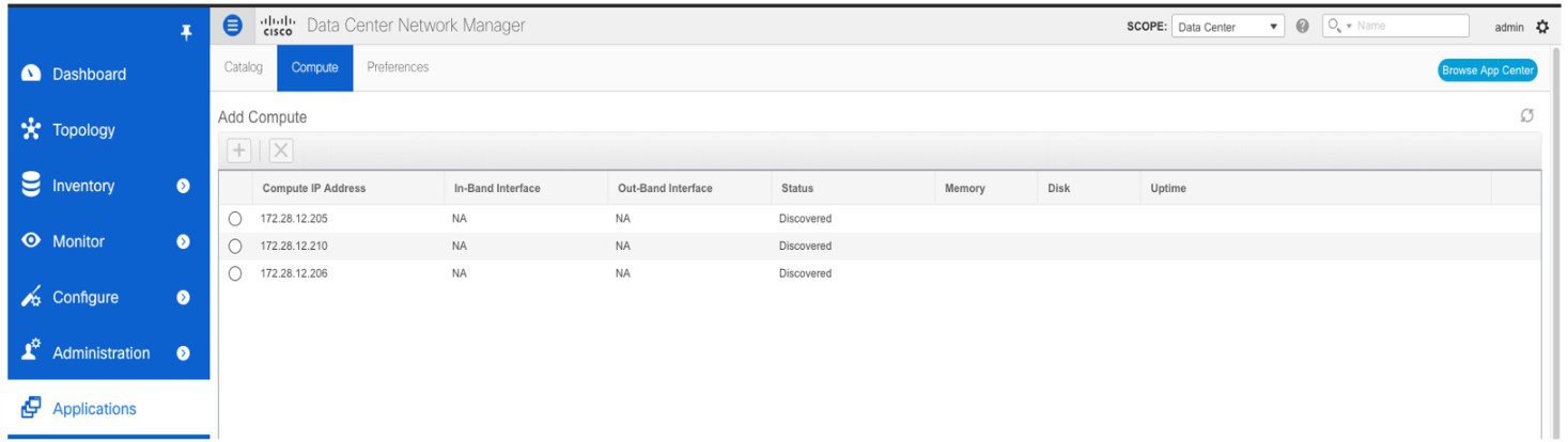
Select a Compute node which is in Discovered status. Click the Add Compute (+) icon.
The Compute window allows you to monitor the health of computes. The health essentially indicates the amount of memory that is left in the compute, this is based on applications that are enabled. If a Compute is not properly communicating with the DCNM Server, the status of the Compute appears as Offline, and no applications are running on Offline Computes. Most applications do not function properly if there are less than three computes, while a short loss of a single Compute node is mostly fine. In such cases, refer to the requirements of the individual applications. |
||
| Step 3 |
In the Add Compute dialog box, view the Compute IP Address, In-Band Interface, and the Out-Band Interface values.
|
||
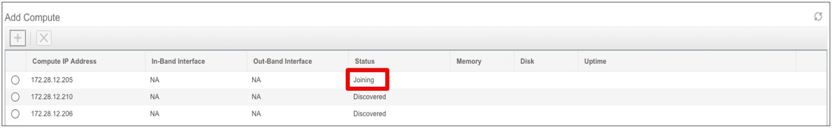
| Step 4 |
Click OK. The Status for that Compute IP changes to Joining.
Wait until the Compute IP status shows Joined.
|
||
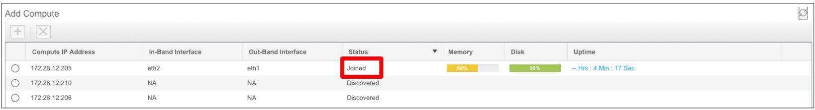
| Step 5 |
Repeat the above steps to add the remaining compute node. All the Computes appear as Joined.
|


Preferences
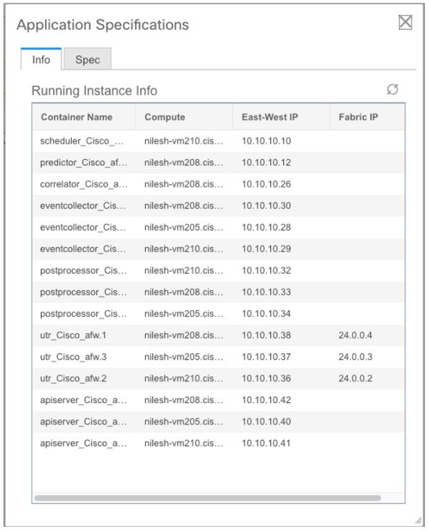
This tab is relevant to the cluster mode of deployment, where the application instances are placed. This tab enables you to compute cluster connectivity and configure the Cluster Connectivity preferences.
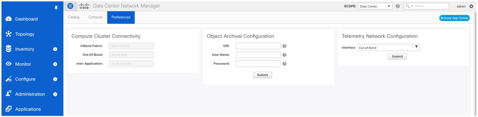
Compute Cluster Connectivity
The fields show the IP address that is used to configure the connectivity interfaces for the cluster node. The IP addresses for in-band fabric, out-of-band fabric, and Inter-Application are displayed.
Object Archival Configuration
The NIA application collects tech support logs for all switches in Fabric, and determines the advisory, based on the data. The logs are saved on the Cisco DCNM server for further analysis or troubleshooting. If you need to download these logs before their life span ends or to create some space on the DCNM server, you can move the logs to a remote server.
In the URI field, enter the relative path to the archive folder, in the format host[:port]/[path to archive]. Enter the username and password to access the URI, in the username and Password field. Click Submit to configure the remote server.
Telemetry Network and NTP Requirements
For the Network Insights Resource (NIR) application, a UTR micro-services running inside the NIR receives the telemetry traffic from the switches either through Out-Of-Band (Eth1) or In-Band (Eth2) interface. By default, the telemetry is configured, and is streaming via the Out-Of-Band interface. You can choose to change it to In-Band interface as well.
Telemetry Using Out-of-band (OOB) Network
By default, the telemetry data is streamed through the management interface of the switches to the Cisco DCNM OOB network eth1 interface. This is a global configuration for all fabrics in Cisco DCNM LAN Fabric Deployment, or switch-groups in Cisco DCNM Classic LAN Deployment. After the telemetry is enabled via NIR application, the telemetry manager in Cisco DCNM will push the necessary NTP server configurations to the switches by using the DCNM OOB IP address as the NTP server IP address. The following example is sample output for show run ntp command.
switch# show run ntp

!Command: show running-config ntp
!Running configuration last done at: Thu Jun 27 18:03:07 2019
!Time: Thu Jun 27 20:32:18 2019

version 7.0(3)I7(6) Bios:version 07.65
ntp server 192.168.126.117 prefer use-vrf management
Telemetry Using In-Band (IB) Network:
The switches stream telemetry data through their front panel ports to Cisco DCNM assuming the connectivity from the switches to the Cisco DCNM In-Band network eth2 interface.


 Feedback