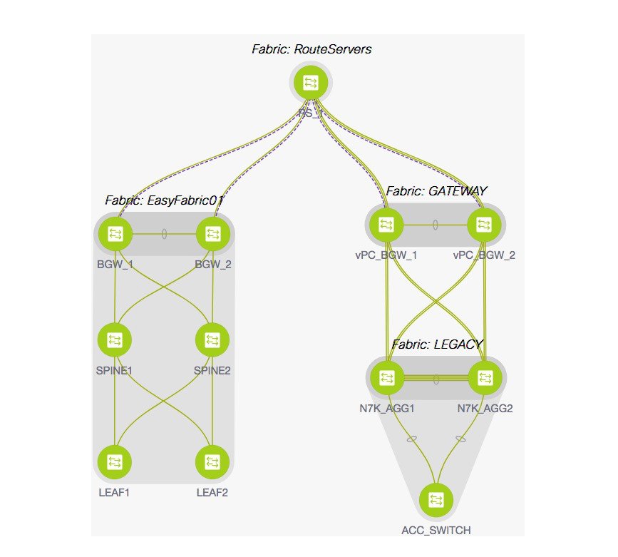
An overlay IFC is a link between the devices’ loopback0 interfaces. For overlay connectivity from the Easy7200 and Easy60000
fabrics to the route server N7k1-RS1 in External65000, a link is enabled between the BGW devices and the N7k1-RS1’s loopback0
interfaces.
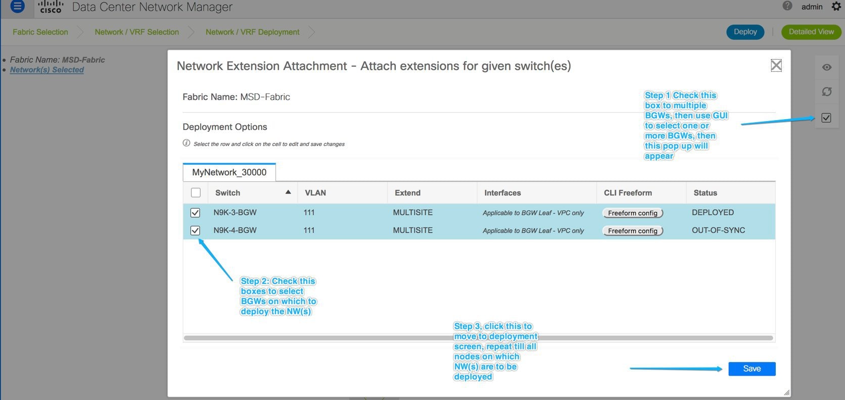
Deploying Overlay IFCs in Easy7200 and Easy60000
-
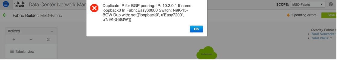
Deploying Overlay IFC from N9K-3-BGW to N7k1-RS1.
-
Deploying Overlay IFC from N9K-4-BGW to N7k1-RS1.
-
Deploying the Overlay IFC from the BGW in Easy60000 to N7k1-RS1.
Deploying Multi-Site Overlay IFCs Through Autoconfiguration
You can automatically configure the Multi-Site overlay through one of these options:
-
Route Server - The BGW forms an overlay to the route server. This option is explained in the example.
-
Direct to BGW: A full mesh of Multi-Site
Overlay IFC from every BGW in a fabric to every BGW in other member
fabrics.
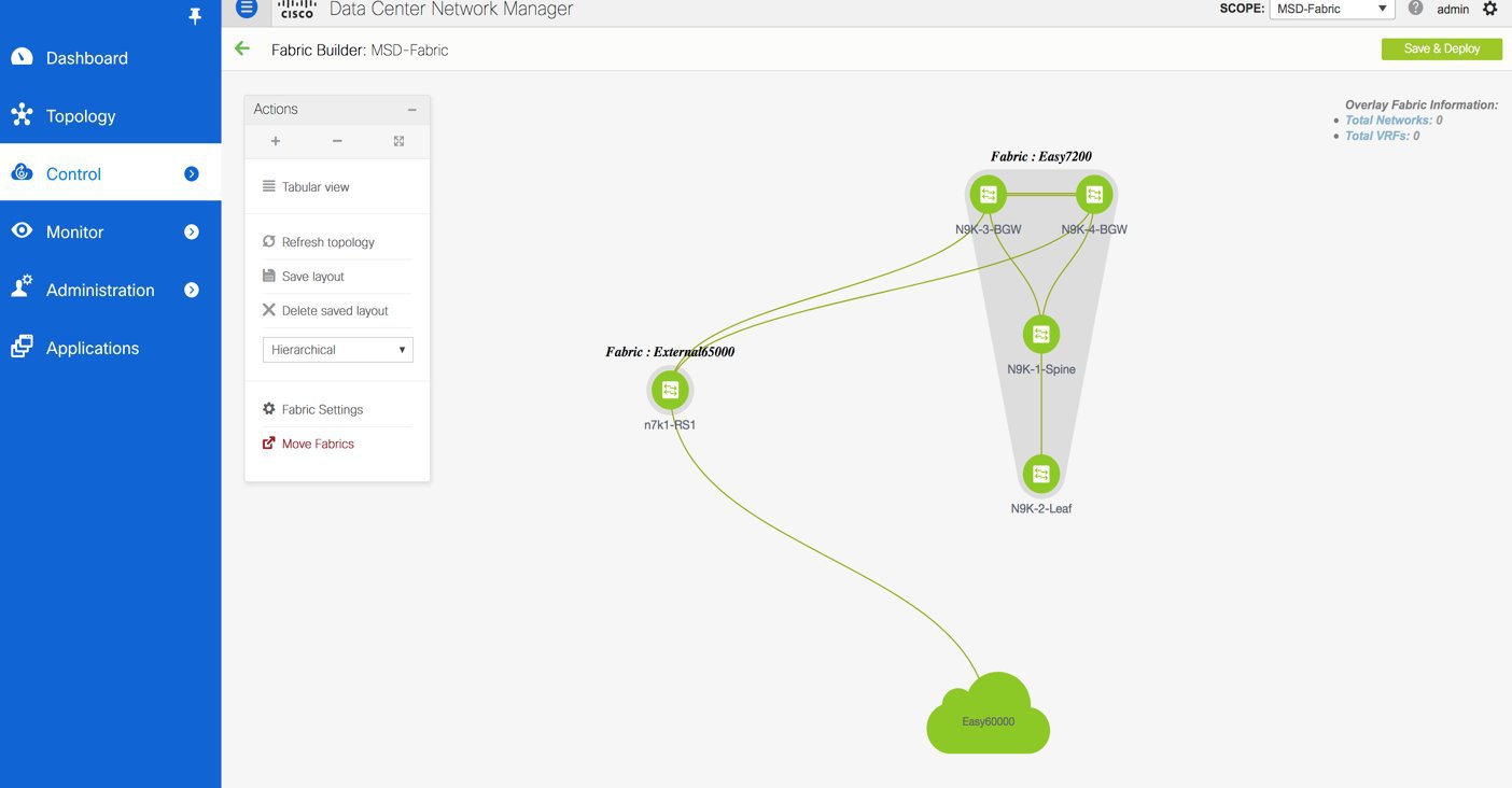
To choose one of the above options, go to the MSD fabric’s settings, select the DCI tab, and set
the Deploy Border Gateway Method field to Route_Server (such as for this example) or Direct to BGW. By default, the Manual option is
selected.
The IFCs needed for deployment of Networks and VRFs at the BGW nodes can be auto configured via the MSD fabric template. The
settings to enable that are in MSD fabric template.
The default mode for the Deploy Border Gateway Method field is Manual, which
implies that the IFCs have to be created via the link tab in MSD fabric. It must be
changed to the Route_Server or Direct to BGW mode for autoconfiguration.
The IFCs created via auto configuration can only be edited or deleted via the link tab in MSD or member fabrics (except external
fabric). As long as an IFC exists, or there is any user defined policy on the physical or logical link, auto configuration
will not touch the IFC configuration.
You can see that Route_Server is selected in the Deploy Border Gateway Method field in the above image.
Route Server
This implies that all BGW devices in all member fabrics will create a Multi-Site overlay BGP connection to one or more route
servers in one or more external fabrics which are members of the MSD fabric.
In this topology, there is one route server n7k1-RS1, and its BGP peering address (1.1.1.1) is shown in the route server list. This
peering address can be configured out of band or with create interface tab in DCNM.
N7k1-RS1 must be imported into the DCNM (in the external fabric, in this example) and
the peering address configured before executing the Save & Deploy option.
You can edit the route server peering IP address list at any time, but you can delete a configured Multi-Site overlay only
through the Links tab.
The BGP AS number of each route server should be specified in the MSD fabric settings. Note that the route server AS number
can be different than the fabric AS number of the external fabric.


 Feedback