Cisco DCNM Interfaces Configuration Guide, Release 4.0
Bias-Free Language
The documentation set for this product strives to use bias-free language. For the purposes of this documentation set, bias-free is defined as language that does not imply discrimination based on age, disability, gender, racial identity, ethnic identity, sexual orientation, socioeconomic status, and intersectionality. Exceptions may be present in the documentation due to language that is hardcoded in the user interfaces of the product software, language used based on RFP documentation, or language that is used by a referenced third-party product. Learn more about how Cisco is using Inclusive Language.
- Updated:
- April 24, 2008
Chapter: Configuring Layer 3 Interfaces
- Information About Layer 3 Interfaces
- Licensing Requirements for Layer 3 Interfaces
- Prerequisites for Layer 3 Interfaces
- Guidelines and Limitations
- Configuring Layer 3 Interfaces
- Configuring a Routed Interface
- Configuring an IPv4 Secondary Address or Helper Address
- Configuring an IPv6 Secondary Address
- Configuring a Subinterface
- Deleting a Subinterface
- Creating a Port-Channel Subinterface
- Deleting a Port-Channel Subinterface
- Configuring the Bandwidth on an Interface
- Configuring a VLAN Network Interface
- Deleting a VLAN Network Interface
- Configuring a Loopback Interface
- Deleting a Loopback Interface
- Displaying Layer 3 Interfaces Statistics
- Related Topics
- Field Descriptions for Layer 3 Interfaces
Configuring Layer 3 Interfaces
This chapter describes how to configure Layer 3 interfaces.
This chapter includes the following sections:
•![]() Information About Layer 3 Interfaces
Information About Layer 3 Interfaces
•![]() Licensing Requirements for Layer 3 Interfaces
Licensing Requirements for Layer 3 Interfaces
•![]() Prerequisites for Layer 3 Interfaces
Prerequisites for Layer 3 Interfaces
•![]() Configuring Layer 3 Interfaces
Configuring Layer 3 Interfaces
•![]() Displaying Layer 3 Interfaces Statistics
Displaying Layer 3 Interfaces Statistics
•![]() Field Descriptions for Layer 3 Interfaces
Field Descriptions for Layer 3 Interfaces
•![]() Feature History for Configuring Layer 3 Interfaces
Feature History for Configuring Layer 3 Interfaces
Information About Layer 3 Interfaces
Layer 3 interfaces forward IPv4 and IPv6 packets to another device using static or dynamic routing protocols. You can use Layer 3 interfaces for IP routing and inter-VLAN routing of Layer 2 traffic.
This section includes the following topics:
Routed Interfaces
You can configure a port as a Layer 2 interface or a Layer 3 interface. A routed interface is a physical port that can route IP traffic to another device. A routed interface is a Layer 3 interface only and does not support Layer 2 protocols, such as the Spanning Tree Protocol (STP).
All Ethernet ports are routed interfaces by default. You can change this default behavior with the CLI setup script.
You can assign an IP address to the port, enable routing, and assign routing protocol characteristics to this routed interface.
You can also create a Layer 3 port channel from routed interfaces. For more information on port channels, see Chapter 5, "Configuring Port Channels."
Routed interfaces and subinterfaces support exponentially-decayed rate counters. NX-OS tracks the following statistics with these averaging counters:
•![]() Input packets/sec
Input packets/sec
•![]() Output packets/sec
Output packets/sec
•![]() Input bytes/sec
Input bytes/sec
•![]() Output bytes/sec
Output bytes/sec
Subinterfaces
You can create virtual subinterfaces on a parent interface configured as a Layer 3 interface. A parent interface can be a physical port or a port channel.
Subinterfaces divide the parent interface into two or more virtual interfaces on which you can assign unique Layer 3 parameters such as IP addresses and dynamic routing protocols. The IP address for each subinterface should be in a different subnet from any other subinterface on the parent interface.
You create a subinterface with a name that consists of the parent interface name (for example, Ethernet 2/1) followed by a period and then by a number that is unique for that subinterface. For example, you could create a subinterface for Ethernet interface 2/ 1 named Ethernet 2/1.1 where .1 indicates the subinterface.
NX-OS enables subinterfaces when the parent interface is enabled. You can shut down a subinterface independent of shutting down the parent interface. If you shut down the parent interface, NX-OS shuts down all associated subinterfaces as well.
One use of subinterfaces is to provide unique Layer 3 interfaces to each virtual local area network (VLAN) supported by the parent interface. In this scenario, the parent interface connects to a Layer 2 trunking port on another device. You configure a subinterface and associate the subinterface to a VLAN ID using 802.1Q trunking.
Figure 4-1 shows a trunking port from a switch that connects to router B on interface E 2/1. This interface contains three subinterfaces that are associated with each of the three VLANs carried by the trunking port.
Figure 4-1 Subinterfaces for VLANs

For more information on VLANs, see the Cisco DCNM Layer 2 Switching Configuration Guide, Release 4.0.
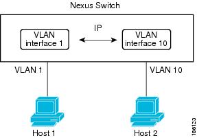
VLAN Interfaces
A VLAN network interface is a virtual routed interface that connects a VLAN on the device to the Layer 3 router engine on the same device. Only one VLAN network interface can be associated with a VLAN, but you need to configure a VLAN network interface for a VLAN only when you wish to route between VLANs or to provide IP host connectivity to the device through a virtual routing and forwarding (VRF) instance that is not the management VRF. When you enable VLAN network interface creation, NX-OS creates a VLAN network interface for the default VLAN (VLAN 1) to permit remote switch administration.

Note ![]() VLAN network interfaceYou cannot delete the VLAN interface for VLAN 1.
VLAN network interfaceYou cannot delete the VLAN interface for VLAN 1.
You can route across VLAN interfaces to provide Layer 3 inter-VLAN routing by configuring a VLAN interface for each VLAN that you want to route traffic to and assigning an IP address on the VLAN interface. For more information on IP addresses and IP routing, see the Cisco DCNM Unicast Routing Configuration Guide, Release 4.0.
Figure 4-2 shows two hosts connected to two VLANs on a device. You can configure VLAN interfaces for each VLAN that allows Host 1 to communicate with Host 2 using IP routing between the VLANs. VLAN 1 communicates at Layer 3 over VLAN interface 1and VLAN 10 communicates at Layer 3 over VLAN interface 10.
Figure 4-2 Connecting Two VLANs with VLAN interfaces
Loopback Interfaces
A loopback interface is a virtual interface with a single endpoint that is always up. Any packet transmitted over a loopback interface is immediately received by this interface. Loopback interfaces emulate a physical interface. You can configure up to 1024 loopback interfaces per VDC, numbered 0 to 1023.
You can use loopback interfaces for performance analysis, testing, and local communications. Loopback interfaces can act as a termination address for routing protocol sessions. This loopback configuration allows routing protocol sessions to stay up even if some of the outbound interfaces are down.
Tunnel Interfaces
DCNM supports tunnel interfaces as IP tunnels. IP tunnels can encapsulate a same-layer or higher layer protocol and transport the result over IP through a tunnel created between two routers. See Chapter 6, "Configuring IP Tunnels" for more information on IP tunnels.
High Availability
Layer 3 interfaces support stateful and stateless restarts. After the switchover, NX-OS applies the runtime configuration after the switchover.
See the Cisco NX-OS High Availability and Redundancy Guide, Release 4.0 for complete information on high availability.
Virtualization Support
Layer 3 interfaces support Virtual Routing and Forwarding instances (VRFs). VRFs exist within virtual device contexts (VDCs). By default, NX-OS places you in the default VDC and default VRF unless you specifically configure another VDC and VRF. A Layer 3 logical interface (VLAN interface, loopback) configured in one VDC is isolated from a Layer 3 logical interface with the same number configured in another VDC. For example, loopback 0 in VDC 1 is independent of loopback 0 in VDC 2.
You can configure up to 1024 loopback interfaces per VDC.
You can associate the interface with a VRF. For VLAN interfaces, you must configure the VLAN interface in the same VDC as the VLAN.
See theCisco DCNM Virtual Device Context Configuration Guide, Release 4.0 for information about VDCs and see the Cisco DCNM Unicast Routing Configuration Guide, Release 4.0 for information about configuring an interface in a VRF.
Note ![]() You must assign an interface to a VRF before you configure the IP address for that interface.
You must assign an interface to a VRF before you configure the IP address for that interface.
Licensing Requirements for Layer 3 Interfaces
The following table shows the licensing requirements for this feature:
Prerequisites for Layer 3 Interfaces
Layer 3 interfaces have the following prerequisites:
•![]() You have installed the Advanced Services license and entered the desired VDC (see the Cisco DCNM Virtual Device Context Configuration Guide, Release 4.0 if you are configuring VDCs.
You have installed the Advanced Services license and entered the desired VDC (see the Cisco DCNM Virtual Device Context Configuration Guide, Release 4.0 if you are configuring VDCs.
•![]() You are familiar with IP addressing and basic configuration. See the Cisco DCNM Unicast Routing Configuration Guide, Release 4.0 for more information on IP addressing.
You are familiar with IP addressing and basic configuration. See the Cisco DCNM Unicast Routing Configuration Guide, Release 4.0 for more information on IP addressing.
Guidelines and Limitations
Layer 3 interfaces have the following configuration guidelines and limitations:
•![]() If you change a Layer 3 interface to a Layer 2 interface, NX-OS shuts down the interface, reenables the interface, and removes all configuration specific to Layer 3.
If you change a Layer 3 interface to a Layer 2 interface, NX-OS shuts down the interface, reenables the interface, and removes all configuration specific to Layer 3.
•![]() If you change a Layer 2 interface to a Layer 3 interface, NX-OS shuts down the interface, reenables the interface, and deletes all configuration specific to Layer 2.
If you change a Layer 2 interface to a Layer 3 interface, NX-OS shuts down the interface, reenables the interface, and deletes all configuration specific to Layer 2.
Configuring Layer 3 Interfaces
You can access Layer 3 interfaces from the Interfaces feature selection. Figure 4-3 shows the Layer 3 interfaces.
Figure 4-3 Configuring Layer 3 Interfaces

For more information about the Data Center Network Manager features, see the Cisco DCNM Fundamentals Configuration Guide, Release 4.0
This section includes the following topics:
•![]() Configuring a Routed Interface
Configuring a Routed Interface
•![]() Configuring an IPv4 Secondary Address or Helper Address
Configuring an IPv4 Secondary Address or Helper Address
•![]() Configuring an IPv6 Secondary Address
Configuring an IPv6 Secondary Address
•![]() Creating a Port-Channel Subinterface
Creating a Port-Channel Subinterface
•![]() Deleting a Port-Channel Subinterface
Deleting a Port-Channel Subinterface
•![]() Configuring the Bandwidth on an Interface
Configuring the Bandwidth on an Interface
•![]() Configuring a VLAN Network Interface
Configuring a VLAN Network Interface
•![]() Deleting a VLAN Network Interface
Deleting a VLAN Network Interface
•![]() Configuring a Loopback Interface
Configuring a Loopback Interface
•![]() Deleting a Loopback Interface
Deleting a Loopback Interface
Configuring a Routed Interface
You can configure any Ethernet port as a routed interface.
DETAILED STEPS
To configure a routed interface, follow these steps:
Step 1 ![]() From the Feature Selector pane, choose Interfaces > Physical > Ethernet.
From the Feature Selector pane, choose Interfaces > Physical > Ethernet.
The available devices appear in the Summary pane (see Figure 4-3).
Step 2 ![]() From the Summary pane, double-click the device to display a list of slots.
From the Summary pane, double-click the device to display a list of slots.
Step 3 ![]() Double-click the slot to display a list of interfaces.
Double-click the slot to display a list of interfaces.
Step 4 ![]() Click the interface that you want to configure as a routed interface.
Click the interface that you want to configure as a routed interface.
The system highlights the interface in the Summary pane, and tabs appear in the Details pane.
Step 5 ![]() From the Details pane, click the Port Details tab.
From the Details pane, click the Port Details tab.
The Port Details tab appears.
Step 6 ![]() From the Port Details tab, expand the Port Mode Settings section.
From the Port Details tab, expand the Port Mode Settings section.
The port mode appears.
Step 7 ![]() From the Mode drop-down list, choose Routed.
From the Mode drop-down list, choose Routed.
The IP address information appears in the Details pane and NX-OS removes any Layer 2 configuration.
Step 8 ![]() (Optional) From the IPv4 Address Settings, set the Primary field to the IPv4 address for this routed interface.
(Optional) From the IPv4 Address Settings, set the Primary field to the IPv4 address for this routed interface.
Step 9 ![]() (Optional) Set the Net mask field to the network mask for this IPv4 address in dotted decimal notation.
(Optional) Set the Net mask field to the network mask for this IPv4 address in dotted decimal notation.
Step 10 ![]() (Optional) From the IPv6 Address Settings area, set the Primary/prefix-length field to the IPv6 address and prefix length for this routed interface.
(Optional) From the IPv6 Address Settings area, set the Primary/prefix-length field to the IPv6 address and prefix length for this routed interface.
The length range is from 1 to 128.
Step 11 ![]() (Optional) To set EUI64, check EUI64.
(Optional) To set EUI64, check EUI64.
Step 12 ![]() (Optional) From the Link local field, enter the link local IPv6 address.
(Optional) From the Link local field, enter the link local IPv6 address.
Step 13 ![]() (Optional) To set this routed interface for link-local routing only, check Use local only.
(Optional) To set this routed interface for link-local routing only, check Use local only.
Step 14 ![]() From the menu bar, choose File > Deploy to apply your changes to the device.
From the menu bar, choose File > Deploy to apply your changes to the device.
Configuring an IPv4 Secondary Address or Helper Address
You can configure secondary addresses or helper addresses for an interface.
DETAILED STEPS
To configure an IPv4 secondary address or helper address on a routed interface, follow these steps:
Step 1 ![]() From the Feature Selector pane, choose Interfaces > Physical > Ethernet.
From the Feature Selector pane, choose Interfaces > Physical > Ethernet.
The available devices appear in the Summary pane (see Figure 4-3).
Step 2 ![]() From the Summary pane, double-click the device to display a list of slots.
From the Summary pane, double-click the device to display a list of slots.
Step 3 ![]() Double-click the slot to display a list of interfaces.
Double-click the slot to display a list of interfaces.
Step 4 ![]() Click the interface that you want to configure as a routed interface.
Click the interface that you want to configure as a routed interface.
The system highlights the interface in the Summary pane, and tabs appear in the Details pane.
Step 5 ![]() From the Details pane, click the Port Details tab.
From the Details pane, click the Port Details tab.
The Port Details tab appears.
Step 6 ![]() From the Port Details tab, expand the Port Mode Settings section.
From the Port Details tab, expand the Port Mode Settings section.
The port mode appears.
Step 7 ![]() (Optional) From the IPv4 Address settings section, in the Secondary area, right-click and choose Add Secondary IP to add a secondary IP address.
(Optional) From the IPv4 Address settings section, in the Secondary area, right-click and choose Add Secondary IP to add a secondary IP address.
Step 8 ![]() From the secondary area, in the IP address field, enter an IPv4 address.
From the secondary area, in the IP address field, enter an IPv4 address.
Step 9 ![]() From the net mask field, enter the network mask for this IPv4 address in dotted decimal notation.
From the net mask field, enter the network mask for this IPv4 address in dotted decimal notation.
Step 10 ![]() (Optional) From the IPv4 Address settings section, in the Helper area, right-click and choose Add Helper IP to add a helper IP address.
(Optional) From the IPv4 Address settings section, in the Helper area, right-click and choose Add Helper IP to add a helper IP address.
Step 11 ![]() From the Helper area, in the IP address field, enter an IPv4 address.
From the Helper area, in the IP address field, enter an IPv4 address.
Step 12 ![]() From the menu bar, choose File > Deploy to apply your changes to the device.
From the menu bar, choose File > Deploy to apply your changes to the device.
Configuring an IPv6 Secondary Address
You can configure secondary addresses or helper addresses for an interface.
DETAILED STEPS
To configure an IPv6 secondary address on a routed interface, follow these steps:
Step 1 ![]() From the Feature Selector pane, choose Interfaces > Physical > Ethernet.
From the Feature Selector pane, choose Interfaces > Physical > Ethernet.
The available devices appear in the Summary pane (see Figure 4-3).
Step 2 ![]() From the Summary pane, double-click the device to display a list of slots.
From the Summary pane, double-click the device to display a list of slots.
Step 3 ![]() Double-click the slot to display a list of interfaces.
Double-click the slot to display a list of interfaces.
Step 4 ![]() Click the interface that you want to configure as a routed interface.
Click the interface that you want to configure as a routed interface.
The system highlights the interface in the Summary pane, and tabs appear in the Details pane.
Step 5 ![]() From the Details pane, click the Port Details tab.
From the Details pane, click the Port Details tab.
The Port Details tab appears.
Step 6 ![]() From the Port Details tab, expand the Port Mode Settings section.
From the Port Details tab, expand the Port Mode Settings section.
The port mode appears.
Step 7 ![]() From the IPv6 Address settings section, in the Secondary area, right-click and choose Add IPv6 Address to add a secondary IPv6 address.
From the IPv6 Address settings section, in the Secondary area, right-click and choose Add IPv6 Address to add a secondary IPv6 address.
Step 8 ![]() From the IP Address/Prefix-length field, enter the IPv6 address and prefix length for this secondary IPv6 address.
From the IP Address/Prefix-length field, enter the IPv6 address and prefix length for this secondary IPv6 address.
Step 9 ![]() (Optional) To set EUI64, check EUI64.
(Optional) To set EUI64, check EUI64.
Step 10 ![]() From the menu bar, choose File > Deploy to apply your changes to the device.
From the menu bar, choose File > Deploy to apply your changes to the device.
Configuring a Subinterface
You can configure one or more subinterfaces on a routed interface or on a port channel made from routed interfaces.
BEFORE YOU BEGIN
Configure the parent interface as a routed interface.
See the "Configuring a Routed Interface" section.
Create the port-channel interface if you want to create a subinterface on that port channel (see the "Configuring Port Channels" section on page 5-12).
DETAILED STEPS
To create a subinterface on a routed interface, follow these steps:
Step 1 ![]() From the Feature Selector pane, choose Interfaces > Physical > Ethernet.
From the Feature Selector pane, choose Interfaces > Physical > Ethernet.
The available devices appear in the Summary pane.
Step 2 ![]() From the Summary pane, double-click the device to display a list of slots.
From the Summary pane, double-click the device to display a list of slots.
Step 3 ![]() Double-click the slot to display a list of interfaces.
Double-click the slot to display a list of interfaces.
Step 4 ![]() Click the interface that you want to configure a subinterface on.
Click the interface that you want to configure a subinterface on.
The system highlights the interface in the Summary pane, and tabs appear in the Details pane.
Step 5 ![]() From the menu bar, choose Ethernet > Add Subinterface to create a subinterface.
From the menu bar, choose Ethernet > Add Subinterface to create a subinterface.
The system highlights the subinterface in the Summary pane, and tabs update in the Details pane.
Step 6 ![]() From the highlighted subinterface field, enter the subinterface number.
From the highlighted subinterface field, enter the subinterface number.
The range is from 1 to 4093.
Step 7 ![]() From the Details pane, click the Port Details tab.
From the Details pane, click the Port Details tab.
The Port Details tab appears.
Step 8 ![]() From the Port Details tab, expand the Basic Settings section.
From the Port Details tab, expand the Basic Settings section.
The basic interface information appears in the Details pane.
Step 9 ![]() (Optional) From the encapsulation area, in the Vlan Id drop-down list, choose the VLAN ID that you want to associate this subinterface with.
(Optional) From the encapsulation area, in the Vlan Id drop-down list, choose the VLAN ID that you want to associate this subinterface with.
Step 10 ![]() From the Port Details tab, expand the IP Address Settings section.
From the Port Details tab, expand the IP Address Settings section.
The IP address information appears in the Details pane.
Step 11 ![]() (Optional) From the IPv4 Address Settings, set the Primary field to the IPv4 address for this subinterface.
(Optional) From the IPv4 Address Settings, set the Primary field to the IPv4 address for this subinterface.
Step 12 ![]() (Optional) From the Net mask field, set the network mask for this IPv4 address in dotted decimal notation.
(Optional) From the Net mask field, set the network mask for this IPv4 address in dotted decimal notation.
Step 13 ![]() (Optional) From the IPv6 Address Settings area, set the Primary/Prefix-length field to the IPv6 address and prefix length for this subinterface.
(Optional) From the IPv6 Address Settings area, set the Primary/Prefix-length field to the IPv6 address and prefix length for this subinterface.
The length range is from 1 to 128.
Step 14 ![]() (Optional) To set EUI64, check EUI64.
(Optional) To set EUI64, check EUI64.
Step 15 ![]() (Optional) From the Link Local field, enter the link local IPv6 address.
(Optional) From the Link Local field, enter the link local IPv6 address.
Step 16 ![]() (Optional) To set this subinterface for link-local routing only, check Use local only.
(Optional) To set this subinterface for link-local routing only, check Use local only.
Step 17 ![]() From the menu bar, choose File > Deploy to apply your changes to the device.
From the menu bar, choose File > Deploy to apply your changes to the device.
Deleting a Subinterface
You can delete a subinterface.
DETAILED STEPS
To delete a subinterface on a routed interface, follow these steps:
Step 1 ![]() From the Feature Selector pane, choose Interfaces > Physical > Ethernet.
From the Feature Selector pane, choose Interfaces > Physical > Ethernet.
The available devices appear in the Summary pane.
Step 2 ![]() From the Summary pane, double-click the device to display a list of slots.
From the Summary pane, double-click the device to display a list of slots.
Step 3 ![]() Double-click the slot to display a list of interfaces.
Double-click the slot to display a list of interfaces.
Step 4 ![]() Click the interface that you want to delete a subinterface on.
Click the interface that you want to delete a subinterface on.
The system highlights the interface in the Summary pane, and tabs appear in the Details pane.
Step 5 ![]() Click the subinterface that you want to delete.
Click the subinterface that you want to delete.
The system highlights the subinterface in the Summary pane.
Step 6 ![]() From the menu bar, choose Ethernet > Delete Subinterface to delete this subinterface.
From the menu bar, choose Ethernet > Delete Subinterface to delete this subinterface.
Step 7 ![]() From the menu bar, choose File > Deploy to apply your changes to the device.
From the menu bar, choose File > Deploy to apply your changes to the device.
Creating a Port-Channel Subinterface
You can create a port-channel subinterface.
DETAILED STEPS
To create a subinterface on a port channel, follow these steps:
Step 1 ![]() From the Feature Selector pane, choose Interfaces > Logical > Port Channel.
From the Feature Selector pane, choose Interfaces > Logical > Port Channel.
The available devices appear in the Summary pane.
Step 2 ![]() From the Summary pane, double-click the device to display a list of existing port channels.
From the Summary pane, double-click the device to display a list of existing port channels.
Step 3 ![]() Right-click the port channel that you want to configure a subinterface on and choose New > Subinterface.
Right-click the port channel that you want to configure a subinterface on and choose New > Subinterface.
The system highlights the port channel subinterface in the Summary pane, and tabs appear in the Details pane.
Step 4 ![]() From the highlighted Channel Id field, enter the subinterface number.
From the highlighted Channel Id field, enter the subinterface number.
The range is from 1 to 4093.
Step 5 ![]() From the Details pane, click the Port Channels Details tab.
From the Details pane, click the Port Channels Details tab.
The Details tab appears.
Step 6 ![]() From the Details tab, expand the Basic Settings section.
From the Details tab, expand the Basic Settings section.
The basic interface information appears in the Details pane.
Step 7 ![]() (Optional) From the encapsulation area, in the VLAN ID drop-down list, choose the VLAN ID that you want to associate this subinterface with.
(Optional) From the encapsulation area, in the VLAN ID drop-down list, choose the VLAN ID that you want to associate this subinterface with.
Step 8 ![]() From the Details tab, expand the IP Address Settings section.
From the Details tab, expand the IP Address Settings section.
The IP address information appears in the Details pane.
Step 9 ![]() (Optional) From the IPv4 Address Settings, set the IP Address field to the IPv4 address for this subinterface.
(Optional) From the IPv4 Address Settings, set the IP Address field to the IPv4 address for this subinterface.
Step 10 ![]() (Optional) From the Net Mask field, set the network mask for this IPv4 address in dotted decimal notation.
(Optional) From the Net Mask field, set the network mask for this IPv4 address in dotted decimal notation.
Step 11 ![]() (Optional) From the IPv6 Address Settings area, set the Primary/Prefix-length field to the IPv6 address and prefix length for this subinterface.
(Optional) From the IPv6 Address Settings area, set the Primary/Prefix-length field to the IPv6 address and prefix length for this subinterface.
The length range is from 1 to 128.
Step 12 ![]() (Optional) To set EUI64, check EUI64.
(Optional) To set EUI64, check EUI64.
Step 13 ![]() (Optional) From the Link Local field, enter the link local IPv6 address.
(Optional) From the Link Local field, enter the link local IPv6 address.
Step 14 ![]() (Optional) To set this subinterface for link-local routing only, check Use local only.
(Optional) To set this subinterface for link-local routing only, check Use local only.
Step 15 ![]() From the menu bar, choose File > Deploy to apply your changes to the device.
From the menu bar, choose File > Deploy to apply your changes to the device.
Deleting a Port-Channel Subinterface
You can delete a port-channel subinterface.
DETAILED STEPS
To delete a subinterface on a port channel, follow these steps:
Step 1 ![]() From the Feature Selector pane, choose Interfaces > Logical > Port Channel.
From the Feature Selector pane, choose Interfaces > Logical > Port Channel.
The available devices appear in the Summary pane.
Step 2 ![]() From the Summary pane, double-click the device to display a list of port channels.
From the Summary pane, double-click the device to display a list of port channels.
Step 3 ![]() Click the port channel that you want to delete a subinterface on.
Click the port channel that you want to delete a subinterface on.
The system highlights the interface in the Summary pane, and tabs appear in the Details pane.
Step 4 ![]() Click the subinterface that you want to delete.
Click the subinterface that you want to delete.
The system highlights the subinterface in the Summary pane.
Step 5 ![]() From the menu bar, choose Port Channel > Delete to delete this subinterface.
From the menu bar, choose Port Channel > Delete to delete this subinterface.
Step 6 ![]() From the menu bar, choose File > Deploy to apply your changes to the device.
From the menu bar, choose File > Deploy to apply your changes to the device.
Configuring the Bandwidth on an Interface
You can configure the bandwidth for a routed interface, port channel, or subinterface. Higher layer protocols use bandwidth parameter to calculate path costs. You can configure the bandwidth on a subinterface with one of the following methods:
•![]() Explicit—Set the bandwidth value for the subinterface directly.
Explicit—Set the bandwidth value for the subinterface directly.
•![]() Inherit—Set the bandwidth that all subinterfaces inherit from the parent interface. This can either be a specific value or can be the bandwidth of the parent interface.
Inherit—Set the bandwidth that all subinterfaces inherit from the parent interface. This can either be a specific value or can be the bandwidth of the parent interface.
If you do not set the subinterface bandwidth or configure it to inherit the bandwidth from the parent interface, NX-OS determines the subinterface bandwidth as follows:
•![]() If the parent interface is up then the bandwidth of the subinterface is the same as the operational speed of the parent interface. For ports, the subinterface bandwidth is the configured or negotiated link speed. For port channels the subinterface bandwidth is the aggregate of the link speeds of individual members of the port channel.
If the parent interface is up then the bandwidth of the subinterface is the same as the operational speed of the parent interface. For ports, the subinterface bandwidth is the configured or negotiated link speed. For port channels the subinterface bandwidth is the aggregate of the link speeds of individual members of the port channel.
•![]() If the parent interface is down, then the bandwidth of the subinterface depends on the type of parent interface:
If the parent interface is down, then the bandwidth of the subinterface depends on the type of parent interface:
–![]() Port-channel subinterfaces have 100Mbps bandwidth for subinterfaces.
Port-channel subinterfaces have 100Mbps bandwidth for subinterfaces.
–![]() 1-Gbps Ethernet ports have 1 Gbps bandwidth for subinterfaces.
1-Gbps Ethernet ports have 1 Gbps bandwidth for subinterfaces.
–![]() 10-Gbps Ethernet ports have 10 Gbps bandwidth for subinterfaces.
10-Gbps Ethernet ports have 10 Gbps bandwidth for subinterfaces.
DETAILED STEPS
To configure the bandwidth on an interface, follow these steps:
Step 1 ![]() From the Feature Selector pane, choose Interfaces > Physical > Ethernet.
From the Feature Selector pane, choose Interfaces > Physical > Ethernet.
The available devices appear in the Summary pane (see Figure 4-3).
Step 2 ![]() From the Summary pane, double-click the device to display a list of slots.
From the Summary pane, double-click the device to display a list of slots.
Step 3 ![]() Double-click the slot to display a list of interfaces.
Double-click the slot to display a list of interfaces.
Step 4 ![]() Click the interface that you want to configure the bandwidth on.
Click the interface that you want to configure the bandwidth on.
The system highlights the interface in the Summary pane, and tabs appear in the Details pane.
Step 5 ![]() From the Details pane, click the Port Details tab.
From the Details pane, click the Port Details tab.
The Port Details tab appears.
Step 6 ![]() From the Port Details tab, expand the Basic Settings section.
From the Port Details tab, expand the Basic Settings section.
The basic settings appears.
Step 7 ![]() In the Bandwidth (kb) field, enter the bandwidth value.
In the Bandwidth (kb) field, enter the bandwidth value.
Step 8 ![]() From the menu bar, choose File > Deploy to apply your changes to the device.
From the menu bar, choose File > Deploy to apply your changes to the device.
Configuring a VLAN Network Interface
You can create VLAN interfaces to provide inter-VLAN routing.
DETAILED STEPS
To create a VLAN network interface, follow these steps:
Step 1 ![]() From the Feature Selector pane, choose Interfaces > Logical > VLAN Network Interface.
From the Feature Selector pane, choose Interfaces > Logical > VLAN Network Interface.
The available devices appear in the Summary pane.
Step 2 ![]() From the Summary pane, double-click the device to display a list of existing VLAN network interfaces.
From the Summary pane, double-click the device to display a list of existing VLAN network interfaces.
Step 3 ![]() From the Details pane, click the Enable VLAN Network Interface link if present.
From the Details pane, click the Enable VLAN Network Interface link if present.
Step 4 ![]() From the menu bar, choose VLAN Network Interface > Add VLAN Network Interface.
From the menu bar, choose VLAN Network Interface > Add VLAN Network Interface.
The system highlights the new VLAN Network Interface in the Summary pane, and tabs appear in the Details pane.
Step 5 ![]() From the highlighted VLAN network interface field, enter the VLAN network interface number.
From the highlighted VLAN network interface field, enter the VLAN network interface number.
The number range is from 1 to 4094.
Step 6 ![]() From the Details pane, click the Details tab.
From the Details pane, click the Details tab.
The Details tab appears.
Step 7 ![]() From the Details tab, expand the IP Address Settings section.
From the Details tab, expand the IP Address Settings section.
The IP address information appears in the Details pane.
Step 8 ![]() (Optional) From the IPv4 Address Settings, set the Primary field to the IPv4 address for this VLAN network interface.
(Optional) From the IPv4 Address Settings, set the Primary field to the IPv4 address for this VLAN network interface.
Step 9 ![]() (Optional) From the Net Mask field, set the network mask for this IPv4 address in dotted decimal notation.
(Optional) From the Net Mask field, set the network mask for this IPv4 address in dotted decimal notation.
Step 10 ![]() (Optional) From the IPv6 Address Settings area, set the Primary/Prefix-length field to the IPv6 address and prefix length for this VLAN network interface.
(Optional) From the IPv6 Address Settings area, set the Primary/Prefix-length field to the IPv6 address and prefix length for this VLAN network interface.
The length range is from 1 to 128.
Step 11 ![]() (Optional) To set EUI64, check EUI64.
(Optional) To set EUI64, check EUI64.
Step 12 ![]() (Optional) From the Link Local field, enter the link local IPv6 address.
(Optional) From the Link Local field, enter the link local IPv6 address.
Step 13 ![]() (Optional) To set this VLAN network interface for link-local routing only, check Use local only.
(Optional) To set this VLAN network interface for link-local routing only, check Use local only.
Step 14 ![]() From the menu bar, choose File > Deploy to apply your changes to the device.
From the menu bar, choose File > Deploy to apply your changes to the device.
Deleting a VLAN Network Interface
You can delete a VLAN network interface.
DETAILED STEPS
To delete a VLAN network interface, follow these steps:
Step 1 ![]() From the Feature Selector pane, choose Interfaces > Logical > VLAN Network Interface.
From the Feature Selector pane, choose Interfaces > Logical > VLAN Network Interface.
The available devices appear in the Summary pane.
Step 2 ![]() From the Summary pane, double-click the device to display a list of existing VLAN network interfaces.
From the Summary pane, double-click the device to display a list of existing VLAN network interfaces.
Step 3 ![]() Click the VLAN network interface that you want to delete.
Click the VLAN network interface that you want to delete.
The system highlights the VLAN network interface in the Summary pane, and tabs appear in the Details pane.
Step 4 ![]() From the menu bar, choose VLAN Network Interface > Delete VLAN Network Interface to delete this VLAN network interface.
From the menu bar, choose VLAN Network Interface > Delete VLAN Network Interface to delete this VLAN network interface.
Step 5 ![]() From the menu bar, choose File > Deploy to apply your changes to the device.
From the menu bar, choose File > Deploy to apply your changes to the device.
Configuring a Loopback Interface
You can configure a loopback interface to create a virtual interface that is always up.
BEFORE YOU BEGIN
Ensure that the IP address of the loopback interface is unique across all routers on the network.
DETAILED STEPS
To create a loopback interface, follow these steps:
Step 1 ![]() From the Feature Selector pane, choose Interfaces > Logical > Loopback.
From the Feature Selector pane, choose Interfaces > Logical > Loopback.
The available devices appear in the Summary pane.
Step 2 ![]() From the Summary pane, double-click the device to display a list of existing loopback interfaces.
From the Summary pane, double-click the device to display a list of existing loopback interfaces.
Step 3 ![]() From the menu bar, choose Loopback > Add Loopback Interface.
From the menu bar, choose Loopback > Add Loopback Interface.
The system highlights the new loopback interface in the Summary pane, and tabs appear in the Details pane.
Step 4 ![]() From the highlighted loopback field, enter the loopback number.
From the highlighted loopback field, enter the loopback number.
The number range is from 1 to 4094.
Step 5 ![]() From the Details pane, click the Details tab.
From the Details pane, click the Details tab.
The Details tab appears.
Step 6 ![]() From the Details tab, expand the IP Address Settings section.
From the Details tab, expand the IP Address Settings section.
The IP address information appears in the Details pane.
Step 7 ![]() (Optional) From the IPv4 Address Settings, set the Primary field to the IPv4 address for this loopback interface.
(Optional) From the IPv4 Address Settings, set the Primary field to the IPv4 address for this loopback interface.
Step 8 ![]() (Optional) From the Net Mask field, set the network mask for this IPv4 address in dotted decimal notation.
(Optional) From the Net Mask field, set the network mask for this IPv4 address in dotted decimal notation.
Step 9 ![]() (Optional) From the IPv6 Address Settings area, set the Primary/Prefix-length field to the IPv6 address and prefix length for this loopback interface.
(Optional) From the IPv6 Address Settings area, set the Primary/Prefix-length field to the IPv6 address and prefix length for this loopback interface.
The length range is from 1 to 128.
Step 10 ![]() (Optional) To set EUI64, check EUI64.
(Optional) To set EUI64, check EUI64.
Step 11 ![]() (Optional) From the Link Local field, enter the link local IPv6 address.
(Optional) From the Link Local field, enter the link local IPv6 address.
Step 12 ![]() (Optional) To set this loopback interface for link-local routing only, check Use local only.
(Optional) To set this loopback interface for link-local routing only, check Use local only.
Step 13 ![]() From the menu bar, choose File > Deploy to apply your changes to the device.
From the menu bar, choose File > Deploy to apply your changes to the device.
Deleting a Loopback Interface
You can delete a loopback interface.
DETAILED STEPS
To delete an loopback interface, follow these steps:
Step 1 ![]() From the Feature Selector pane, choose Interfaces > Logical > Loopback.
From the Feature Selector pane, choose Interfaces > Logical > Loopback.
The available devices appear in the Summary pane.
Step 2 ![]() From the Summary pane, double-click the device to display a list of existing loopback interfaces.
From the Summary pane, double-click the device to display a list of existing loopback interfaces.
Step 3 ![]() Click the loopback interface that you want to delete.
Click the loopback interface that you want to delete.
The system highlights the loopback interface in the Summary pane, and tabs appear in the Details pane.
Step 4 ![]() From the menu bar, choose Loopback > Delete Loopback Interface to delete this loopback interface.
From the menu bar, choose Loopback > Delete Loopback Interface to delete this loopback interface.
Step 5 ![]() From the menu bar, choose File > Deploy to apply your changes to the device.
From the menu bar, choose File > Deploy to apply your changes to the device.
Displaying Layer 3 Interfaces Statistics
You can configure DCNM to collect layer 3 interface statistics. Choose Interfaces from the Feature Selector and navigate to the interface that you want to collect statistics on.
The following windows appear in the Statistics tab:
•![]() Port Traffic Statistics—Collects input and output (packet and byte) counters, broadcast, multicast, and unicast traffic.
Port Traffic Statistics—Collects input and output (packet and byte) counters, broadcast, multicast, and unicast traffic.
•![]() Port Error Statistics—(physical ports only) Collects a variety of error statistics for the interface.
Port Error Statistics—(physical ports only) Collects a variety of error statistics for the interface.
See the Cisco DCNM Fundamentals Configuration Guide for more information on collecting statistics for layer 3 interfaces.
Related Topics
The following topics can give more information on layer 3 interfaces:
•![]() Chapter 5, "Configuring Port Channels"
Chapter 5, "Configuring Port Channels"
•![]() Cisco DCNM Unicast Routing Configuration Guide, Release 4.0
Cisco DCNM Unicast Routing Configuration Guide, Release 4.0
Field Descriptions for Layer 3 Interfaces
This section includes the following field descriptions for layer 3 interfaces:
Routed Interfaces
Field descriptions for routed interfaces are covered in Chapter 2, "Configuring Basic Interface Parameters."
Loopback
•![]() This section includes the following field descriptions for loopback interfaces:Loopback: Details Tab: Basic Settings Section
This section includes the following field descriptions for loopback interfaces:Loopback: Details Tab: Basic Settings Section
•![]() Loopback: Details Tab: IP Address Settings Section
Loopback: Details Tab: IP Address Settings Section
Loopback: Details Tab: Basic Settings Section
Loopback: Details Tab: IP Address Settings Section
Loopback: Statistics Tab
VLAN Network Interface
•![]() This section includes the following field descriptions for VLAN network interfaces:
This section includes the following field descriptions for VLAN network interfaces:
•![]() VLAN Network Interface: Details Tab: Basic Settings Section
VLAN Network Interface: Details Tab: Basic Settings Section
•![]() VLAN Network Interface: Details Tab: IP Address Settings Section
VLAN Network Interface: Details Tab: IP Address Settings Section
•![]() VLAN Network Interface: Statistics Tab
VLAN Network Interface: Statistics Tab
VLAN Network Interface: Details Tab: Basic Settings Section
VLAN Network Interface: Details Tab: IP Address Settings Section
VLAN Network Interface: Statistics Tab
Additional References
For additional information related to implementing Layer 3 interfaces, see the following sections:
•![]() MIBs
MIBs
Related Documents
MIBs
|
|
|
|---|---|
• • • |
To locate and download MIBs, go to the following URL: http://www.cisco.com/public/sw-center/netmgmt/cmtk/mibs.shtml |
Standards
|
|
|
|---|---|
No new or modified standards are supported by this feature, and support for existing standards has not been modified by this feature. |
— |
Feature History for Configuring Layer 3 Interfaces
Table 4-7 lists the release history for this feature.
|
|
|
|
|---|---|---|
SVI |
4.0(3) |
Changed to VLAN Network Interface on entire DCNM and all documentation. |
 Feedback