Cisco Nexus 7000 Series NX-OS Interfaces Configuration Guide, Release 6.x
Bias-Free Language
The documentation set for this product strives to use bias-free language. For the purposes of this documentation set, bias-free is defined as language that does not imply discrimination based on age, disability, gender, racial identity, ethnic identity, sexual orientation, socioeconomic status, and intersectionality. Exceptions may be present in the documentation due to language that is hardcoded in the user interfaces of the product software, language used based on RFP documentation, or language that is used by a referenced third-party product. Learn more about how Cisco is using Inclusive Language.
This chapter describes how to configure Layer 2 interfaces on Cisco NX-OS devices.
Finding Feature
Information
Your software release might not support all the features documented in this module. For the latest caveats and feature information,
see the Bug Search Tool at https://tools.cisco.com/bugsearch/ and the release notes for your software release. To find information about the features documented in this module, and to
see a list of the releases in which each feature is supported, see the "New and Changed Information"chapter or the Feature
History table in this chapter.
Feature History for
Configuring Layer 2 Interfaces
This table includes only the updates for those releases that have resulted in additions or changes to the feature.
Table 1. Feature History
for Configuring Layer 2 Interfaces
Feature Name
Release
Feature
Information
Native VLAN tagging on Trunk Ports
6.2(10)
Added support for the switchport trunk native vlan tag command and added the exclude control keywords to the vlan dot1q tag native command.
Display
policy errors on interfaces and vlans
6.2(2)
Added the
show
interface status error policy command to display errors on interfaces
and VLANs that are inconsistent with hardware policies.
Clear SNMP
counters from the interface
6.2(2)
Updated the
clear counters interface command to include the
snmp keyword that provides an option to clear SNMP
values from the interface.
SVI
autostate disable
6.2(2)
Added the
no
autostate command that allows an SVI to be kept up even if no
interface is up in the corresponding VLAN.
Slow drain
device detection and congestion avoidance
6.1(1)
Added
configuration for slow drain device detection and avoiding congestion.
Default
interfaces
5.2(1)
Added the
default interface command to clear configuration of
multiple interfaces.
SVI
autostate exclude
5.2(1)
Added the
switchport autostate exclude command to prevent a
port’s state from affecting the up or down state of the SVI.
Three
configurable sampling intervals for interface statistics
4.2(1)
Added the
load-interval command.
Information About
Layer 2 Interfaces
Note
From Cisco NX-OS Release 5.2, the Cisco Nexus 7000 Series devices support FabricPath Layer 2 interfaces. See the Cisco Nexus 7000 Series NX-OS FabricPath Command Reference for complete information about the FabricPath feature and interfaces.
From Cisco NX-OS Release 5.1, a Layer 2 port can function as either one of the following:
A trunk port
An access port
A private VLAN port (see the for more information about private VLANs)
From Cisco NX-OS Release 5.2(1), a Layer 2 port can also function as a shared interface. You cannot configure an access interface
as a shared interface. See the for information about shared interfaces.
A Layer 2 port can
function as either a trunk port, an access port, or a private VLAN port.
Note
From Cisco NX-OS Release 6.1, the slow drain device detection and
congestion avoidance mechanism is supported on F series I/O modules that carry
the Fabric Channel over Ethernet (FCoE) traffic. See the "Configuring
Slow Drain Device Detection and Congestion Avoidance" section for more
information about configuring slow drain device detection and congestion
avoidance on the Cisco Nexus 7000 Series platform.
You can configure Layer 2 switching ports as access or trunk
ports. Trunks carry the traffic of multiple VLANs over a single link and allow
you to extend VLANs across an entire network. All Layer 2 switching ports
maintain media access control (MAC) address tables.
A Layer 2 port can function as either a trunk port, an access port, or a private VLAN port. See the for more information
about private VLANs.
Access and Trunk
Interfaces
Note
Cisco NX-OS device
supports only IEEE 802.1Q-type VLAN trunk encapsulation.
A Layer 2 port can be
configured as an access or a trunk port as follows:
An access port can
have only one VLAN configured on that port; it can carry traffic for only one
VLAN.
A trunk port can
have two or more VLANs configured on that port; it can carry traffic for
several VLANs simultaneously.
By default, all ports
on the device are Layer 3 ports.
You can make all ports Layer 2 ports using the setup script or by entering the system default switchport command. See the for information about using the setup script. To configure the port as a Layer 2 port using the CLI, use
the switchport command.
All ports in one trunk must be in the same virtual device context (VDC). See the for information about VDCs.
All ports in the same
trunk must be in the same VDC, and trunk ports cannot carry VLANs from
different VDCs.
The figure below shows
how you can use trunk ports in the network. The trunk port carries traffic for
two or more VLANs.
Figure 1. Trunk and Access
Ports and VLAN Traffic
See the for information about VLANs.
In order to correctly
deliver the traffic on a trunk port with several VLANs, the device uses the
IEEE 802.1Q encapsulation, or tagging, method (see the “IEEE
802.1Q Encapsulation” section for more information).
Note
See the for information about subinterfaces on Layer 3 interfaces.
To optimize the
performance on access ports, you can configure the port as a host port. Once
the port is configured as a host port, it is automatically set as an access
port, and channel grouping is disabled. Use the host designation to decrease
the time that it takes the designated port to begin to forward packets.
Only an end station
can be set as a host port; you will receive an error message if you attempt to
configure other ports as hosts.
If an access port
receives a packet with an 802.1Q tag in the header other than the access VLAN
value, that port drops the packet without learning its MAC source address.
A Layer 2 interface
can function as either an access port or a trunk port; it cannot function as
both port types simultaneously.
When you change a
Layer 2 interface back to a Layer 3 interface, that interface loses all the
Layer 2 configuration and resumes the default VLAN configurations.
IEEE 802.1Q
Encapsulation
Note
For information about VLANs, see the .
A trunk is a
point-to-point link between the switch and another networking device. Trunks
carry the traffic of multiple VLANs over a single link and allow you to extend
VLANs across an entire network.
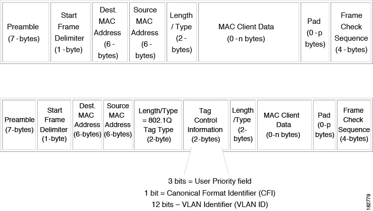
To correctly deliver
the traffic on a trunk port with several VLANs, the device uses the IEEE 802.1Q
encapsulation, or tagging, method that uses a tag that is inserted into the
frame header (see the figure below). This tag carries information about the
specific VLAN to which the frame and packet belong. This method allows packets
that are encapsulated for several different VLANs to traverse the same port and
maintain traffic separation between the VLANs. Also, the encapsulated VLAN tag
allows the trunk to move traffic end-to-end through the network on the same
VLAN.
Figure 2. Header Without
and With 802.1Q Tag
Access VLANs
Note
If you assign an
access VLAN that is also a primary VLAN for a private VLAN, all access ports
with that access VLAN will also receive all the broadcast traffic for the
primary VLAN in the private VLAN mode.
See the for complete information on private VLANs.
When you configure a
port in access mode, you can specify which VLAN will carry the traffic for that
interface. If you do not configure the VLAN for a port in access mode, or an
access port, the interface carries traffic for the default VLAN (VLAN1).
You can change the
access port membership in a VLAN by specifying the new VLAN. You must create
the VLAN before you can assign it as an access VLAN for an access port. If you
change the access VLAN on an access port to a VLAN that is not yet created, the
system shuts that access port down.
If an access port
receives a packet with an 802.1Q tag in the header other than the access VLAN
value, that port drops the packet without learning its MAC source address.
Native VLAN IDs for
Trunk Ports
A trunk port can carry
nontagged packets simultaneously with the 802.1Q tagged packets. When you
assign a default port VLAN ID to the trunk port, all untagged traffic travels
on the default port VLAN ID for the trunk port, and all untagged traffic is
assumed to belong to this VLAN. This VLAN is referred to as the native VLAN ID
for a trunk port. That is, the native VLAN ID is the VLAN that carries untagged
traffic on trunk ports.
Note
Native VLAN ID
numbers must match on both ends of the trunk.
The trunk port sends
an egressing packet with a VLAN that is equal to the default port VLAN ID as
untagged; all the other egressing packets are tagged by the trunk port. If you
do not configure a native VLAN ID, the trunk port uses the default VLAN.
Note
You cannot use a
Fibre Channel over Ethernet (FCoE) VLAN as a native VLAN for an Ethernet trunk
switchport.
Tagging Native VLAN
Traffic
The Cisco software
supports the IEEE 802.1Q standard on trunk ports. In order to pass untagged
traffic through the trunk ports, you must create a VLAN that does not tag any
packets (or you can use the default VLAN). Untagged packets can pass through
trunk ports and access ports.
However, all packets
that enter the device with an 802.1Q tag that matches the value of the native
VLAN on the trunk are stripped of any tagging and egress the trunk port as
untagged packets. This situation can cause problems because you may want to
retain the tagging on packets on the native VLAN for the trunk port.
You can configure the
device to drop all untagged packets on the trunk ports and to retain the
tagging of packets entering the device with 802.1Q values that are equal to
that of the native VLAN ID. All control traffic still passes on the native
VLAN. This configuration is global; trunk ports on the device either do or do
not retain the tagging for the native VLAN.
From Cisco NX-OS Release 6.2(10), you can specify whether control and data packets are tagged or untagged using the switchport trunk native vlan tag command at the port level. For example, by using the switchport trunk native vlan tag exclude control command, you can specify that data packets are tagged and control packets are untagged.
Note
When a port-level
configuration is applied, the global configuration for native VLAN tagging will
no longer take effect on that port. Port-level configurations take priority
over global configurations.
By default, a trunk
port sends traffic to and receives traffic from all VLANs. All VLAN IDs are
allowed on each trunk. However, you can remove VLANs from this inclusive list
to prevent traffic from the specified VLANs from passing over the trunk. Later,
you can add any specific VLANs that you may want the trunk to carry traffic for
back to the list.
To partition the
Spanning Tree Protocol (STP) topology for the default VLAN, you can remove
VLAN1 from the list of allowed VLANs. Otherwise, VLAN1, which is enabled on all
ports by default, will have a very big STP topology, which can result in
problems during STP convergence. When you remove VLAN1, all data traffic for
VLAN1 on this port is blocked, but the control traffic continues to move on the
port.
See the for more information about STP.
From Cisco Release 5.2, you can change the block of VLANs reserved for internal use. See the for more information about changing
the reserved VLANs.
Default
Interfaces
The default interface feature allows you to clear the existing
configuration of multiple interfaces such as Ethernet, loopback, VLAN network,
port-channel, and tunnel interfaces. All user configuration under a specified
interface will be deleted. You can optionally create a checkpoint before
clearing the interface configuration so that you can later restore the deleted
configuration. You can use the default interface feature to clear the
configured parameters for both physical and logical interfaces such as the
Ethernet, loopback, VLAN network, tunnel, and the port-channel interface.
Note
The default interface feature is not supported for management
interfaces because the device could go to an unreachable state.
Note
A maximum of eight
ports can be selected for the default interface. The default interfaces feature
is not supported for management interfaces because the device could go to an
unreachable state.
Switch Virtual
Interface and Autostate Behavior
In Cisco NX-OS, a switch virtual interface (SVI) represents a logical
interface between the bridging function and the routing function of a VLAN in
the device.
The operational state of this interface is governed by the state of the
various ports in its corresponding VLAN. An SVI interface on a VLAN comes up
when at least one port in that VLAN is in the Spanning Tree Protocol (STP)
forwarding state. Similarly, this interface goes down when the last STP
forwarding port goes down or goes to another STP state.
SVI Autostate
Exclude
Typically, when a VLAN
interface has multiple ports in the VLAN, the SVI goes to the down state when
all the ports in the VLAN go down. You can use the SVI autostate exclude
feature to exclude specific ports and port channels while defining the status
of the SVI (up or down) even if it belongs to the same VLAN. For example, even
if the excluded port or port channel is in the up state and other ports are in
the down state in the VLAN, the SVI state is changed to down.
You can configure the SVI autostate Exclude feature on an Ethernet
interface or a port channel. You can use the autostate Exclude option to enable
or disable the port from bringing up or down the SVI calculation and applying
it to all VLANs that are enabled on the selected port. You can also use the SVI
autostate Exclude VLAN feature to exclude a VLAN from the autostate excluded
interface.
Note
You can use the SVI
autostate exclude feature only for switched physical Ethernet ports and port
channels.
SVI Autostate
Disable
You can also use the SVI for inband managment of a device. Specifically,
you can configure the autostate disable feature to keep an SVI up even if no
interface is up in the corresponding VLAN. You can configure this feature for
the system (for all SVIs) or for an individual SVI.
High
Availability
The software supports
high availability for Layer 2 ports.
The device supports
virtual device contexts (VDCs).
All ports in the same
trunk must be in the same VDC, and trunk ports cannot carry VLANs from
different VDCs.
Note
See the for complete information about VDCs and assigning resources.
Prerequisites for
Layer 2 Interfaces
Layer 2 interfaces have the following prerequisites:
You are logged onto the device.
You must configure the port as a Layer 2 port before you can use
the switchport mode command. By default, all ports on the device are Layer 3
ports.
Default Settings for
Layer 2 Interfaces
Table 2. Default Access
and Trunk Port Mode Parameters
Parameter
Default
Switchport
mode
Access
Allowed
VLANs
1 to 3967,
4048 to 4094
Access VLAN
ID
VLAN1
Native VLAN
ID
VLAN1
Native VLAN
ID tagging
Disabled
Administrative state
Shut
SVI
autostate
Enabled
Guidelines and
Limitations for Layer 2 Interfaces
VLAN trunking has
the following configuration guidelines and limitations:
A port can be
either a Layer 2 or a Layer 3 interface; it cannot be both simultaneously.
QSFP-100G-DR-S and QSFP-100G-FR-S transceivers does not support breakout.
You can view a link-up time difference of few seconds for QSFP-100G-DR-S transceiver.
When you change
a Layer 3 port to a Layer 2 port or a Layer 2 port to a Layer 3 port, all
layer-dependent configuration is lost. When you change an access or trunk port
to a Layer 3 port, all information about the access VLAN, native VLAN, allowed
VLANs, and so forth, is lost.
Do not connect
devices with access links because access links may partition a VLAN.
When connecting
Cisco devices through an 802.1Q trunk, make sure that the native VLAN for an
802.1Q trunk is the same on both ends of the trunk link. If the native VLAN on
one end of the trunk is different from the native VLAN on the other end,
spanning tree loops might result.
Disabling
spanning tree on the native VLAN of an 802.1Q trunk without disabling spanning
tree on every VLAN in the network can cause spanning tree loops. You must leave
spanning tree enabled on the native VLAN of an 802.1Q trunk. If you cannot
leave spanning tree enabled, you must disable spanning tree on every VLAN in
the network. Make sure that your network has no physical loops before you
disable spanning tree.
When you connect
two Cisco devices through 802.1Q trunks, the devices exchange spanning tree
bridge protocol data units (BPDUs) on each VLAN allowed on the trunks. The
BPDUs on the native VLAN of the trunk are sent untagged to the reserved IEEE
802.1D spanning tree multicast MAC address (01-80-C2-00-00-00). The BPDUs on
all other VLANs on the trunk are sent tagged to the reserved Cisco Shared
Spanning Tree (SSTP) multicast MAC address (01-00-0c-cc-cc-cd).
Non-Cisco 802.1Q
devices maintain only a single instance of spanning tree (the Mono Spanning
Tree) that defines the spanning tree topology for all VLANs. When you connect a
Cisco switch to a non-Cisco switch through an 802.1Q trunk, the Mono Spanning
Tree of the non-Cisco switch and the native VLAN spanning tree of the Cisco
switch combine to form a single spanning tree topology known as the Common
Spanning Tree (CST).
Because Cisco
devices transmit BPDUs to the SSTP multicast MAC address on VLANs other than
the native VLAN of the trunk, non-Cisco devices do not recognize these frames
as BPDUs and flood them on all ports in the corresponding VLAN. Other Cisco
devices connected to the non-Cisco 802.1Q cloud receive these flooded BPDUs.
This BPDU reception allows Cisco switches to maintain a per-VLAN spanning tree
topology across a cloud of non-Cisco 802.1Q devices. The non-Cisco 802.1Q cloud
that separates the Cisco devices is treated as a single broadcast segment
between all devices connected to the non-Cisco 802.1Q cloud through 802.1Q
trunks.
Make certain
that the native VLAN is the same on all of the 802.1Q trunks that connect the
Cisco devices to the non-Cisco 802.1Q cloud.
If you are
connecting multiple Cisco devices to a non-Cisco 802.1Q cloud, all of the
connections must be through 802.1Q trunks. You cannot connect Cisco devices to
a non-Cisco 802.1Q cloud through access ports because doing so places the
access port on the Cisco device into the spanning tree “port inconsistent”
state and no traffic will pass through the port.
You can group
trunk ports into port-channel groups, but all trunks in the group must have the
same configuration. When a group is first created, all ports follow the
parameters set for the first port to be added to the group. If you change the
configuration of one of these parameters, the device propagates that setting to
all ports in the group, such as the allowed VLANs and the trunk status. For
example, if one port in a port group ceases to be a trunk, all ports cease to
be trunks.
If you try to
enable 802.1X on a trunk port, an error message appears, and 802.1X is not
enabled. If you try to change the mode of an 802.1X-enabled port to trunk, the
port mode is not changed.
Changing the
native VLAN on an access port or trunk port will flap the interface. This
behavior is expected.
Configuring Access
and Trunk Interfaces
If you are familiar with the Cisco IOS CLI, be aware that the Cisco
NX-OS commands for this feature might differ from the Cisco IOS commands that
you would use.
All VLANs on a trunk must be in the same VDC.
Configuring a VLAN
Interface as a Layer 2 Access Port
You can configure a Layer 2 port as an access port. An access port
transmits packets on only one, untagged VLAN. You specify which VLAN traffic
that the interface carries, which becomes the access VLAN. If you do not
specify a VLAN for an access port, that interface carries traffic only on the
default VLAN. The default VLAN is VLAN1.
The VLAN must exist before you can specify that VLAN as an access
VLAN. The system shuts down an access port that is assigned to an access VLAN
that does not exist.
Before you begin
Ensure that you are
configuring a Layer 2 interface.
Sets the
interface as a nontrunking nontagged, single-VLAN Layer 2 interface. An access
port can carry traffic in one VLAN only. By default, an access port carries
traffic for VLAN1; to set the access port to carry traffic for a different
VLAN, use the
switchport access vlan command.
Step 4
switch(config-if)#
switchport access vlanvlan-id
Specifies the
VLAN for which this access port will carry traffic. If you do not enter this
command, the access port carries traffic on VLAN1 only; use this command to
change the VLAN for which the access port carries traffic.
Step 5
switch(config-if)#
exit
Exits the
interface mode.
Step 6
switch(config)#
exit
Exits global
configuration mode.
Step 7
(Optional) switch#
show interface
(Optional)
Displays the
interface status and information.
Step 8
(Optional) switch#
show
interface status error policy [detail]
(Optional)
Displays the
interfaces and VLANs that produce errors during policy programming to ensure
that policies are consistent with hardware policies.
Use the
detail command to display the details of the
interfaces that produce an error.
Step 9
(Optional) switch#
no shutdown
(Optional)
Clears the
errors on the interfaces and VLANs where policies correspond with hardware
policies. This command allows policy programming to continue and the port to
come up. If policies do not correspond, the errors are placed in an
error-disabled policy state.
You should apply
the
switchport
host command only to interfaces that are connected to an end station.
You can optimize the performance of access ports that are connected to end stations by simultaneously setting that port as
an access port. An access host port handles the STP like an edge port and immediately moves to the forwarding state without
passing through the blocking and learning states. Configuring an interface as an access host port also disables port channeling
on that interface.
Note
See the for information about port-channel interfaces
Before you begin
Ensure that you are
configuring the correct interface to an interface that is an end station.
Procedure
Command or Action
Purpose
Step 1
switch#
configure
terminal
Enters the
global configuration mode.
Step 2
switch(config)#
interfacetype
slot/port
Specifies an
interface to configure, and enters interface configuration mode.
Step 3
switch(config-if)#
switchport host
Sets the
interface to be an access host port, which immediately moves to the spanning
tree forwarding state and disables port channeling on this interface.
Note
Apply this
command only to end stations.
Step 4
switch(config-if)#
exit
Exits the
interface mode.
Step 5
switch(config)#
exit
Exits the
configuration mode.
Step 6
(Optional) switch#
show interface
(Optional)
Displays the
interface status and information.
Step 7
(Optional) switch#
show
interface status error policy [detail]
(Optional)
Displays the
interfaces and VLANs that produce errors during policy programming to ensure
that policies are consistent with hardware policies.
Use the
detail command to display the details of the
interfaces that produce an error.
Step 8
(Optional) switch#
no shutdown
(Optional)
Clears the
errors on the interfaces and VLANs where policies correspond with hardware
policies. This command allows policy programming to continue and the port to
come up. If policies do not correspond, the errors are placed in an
error-disabled policy state.
You can configure a Layer 2 port as a trunk port. A trunk port
transmits untagged packets for one VLAN plus encapsulated, tagged, packets for
multiple VLANs. (See the “IEEE
802.1Q Encapsulation” section for information about encapsulation.)
Note
The device supports 802.1Q encapsulation only.
Before you begin
Before you configure
a trunk port, ensure that you are configuring a Layer 2 interface.
Sets the
interface as a Layer 2 trunk port. A trunk port can carry traffic in one or
more VLANs on the same physical link (VLANs are based on the trunk-allowed
VLANs list). By default, a trunk interface can carry traffic for all VLANs. To
specify that only certain VLANs are allowed on the specified trunk, use the
switchport trunk allowed vlan command.
Step 4
switch(config-if)#
exit
Exits the
interface mode.
Step 5
switch(config)#
exit
Exits the
configuration mode.
Step 6
(Optional) switch#
show interface
(Optional)
Displays the
interface status and information.
Step 7
(Optional) switch#
show
interface status error policy [detail]
(Optional)
Displays the
interfaces and VLANs that produce errors during policy programming to ensure
that policies are consistent with hardware policies.
Use the
detail command to display the details of the
interfaces that produce an error.
Step 8
(Optional) switch#
no shutdown
(Optional)
Clears the
errors on the interfaces and VLANs where policies correspond with hardware
policies. This command allows policy programming to continue and the port to
come up. If policies do not correspond, the errors are placed in an
error-disabled policy state.
Configuring the
Native VLAN for 802.1Q Trunking Ports
You can configure the native VLAN for 802.1Q trunk ports. If you do
not configure this parameter, the trunk port uses the default VLAN as the
native VLAN ID.
Note
You cannot configure an FCoE VLAN as a native VLAN for an Ethernet
interface.
Sets the native
VLAN for the 802.1Q trunk. Valid values are from 1 to 4094, except those VLANs
reserved for internal use. The default value is VLAN1.
Step 4
switch(config-if)#
exit
Exits the
interface mode.
Step 5
switch(config)#
exit
Exits global
configuration mode.
Step 6
switch#
show vlan
Displays the
status and information of VLANs.
Step 7
(Optional) switch#
show
interface status error policy [detail]
(Optional)
Displays the
interfaces and VLANs that produce errors during policy programming to ensure
that policies are consistent with hardware policies.
Use the
detail command to display the details of the
interfaces that produce an error.
Step 8
(Optional) switch#
no shutdown
(Optional)
Clears the
errors on the interfaces and VLANs where policies correspond with hardware
policies. This command allows policy programming to continue and the port to
come up. If policies do not correspond, the errors are placed in an
error-disabled policy state.
You can specify the
IDs for the VLANs that are allowed on the specific trunk port.
The
switchport trunk allowed
vlanvlan-list command replaces the current VLAN list
on the specified port with the new list. You are prompted for confirmation
before the new list is applied.
If you are doing a copy and paste of a large configuration, you might see some failures because the CLI is waiting for a confirmation
before accepting other commands. To avoid this problem, you can disable prompting by using the terminal dont-ask command before you paste the configuration.
Before you begin
Before you configure
the allowed VLANs for the specified trunk ports, ensure that you are
configuring the correct interfaces and that the interfaces are trunks.
From Cisco Release 5.2, you can change the block of VLANs reserved for internal use. See the for more information about changing
the reserved VLANs.
Sets the allowed VLANs for the trunk interface. The default is to allow all VLANs on the trunk interface: 1 to 3967 and 4048
to 4094. VLANs 3968 to 4047 are the default VLANs reserved for internal use by default. By default, all VLANs are allowed
on all trunk interfaces. From Cisco Release 5.2(1), the default reserved VLANs are 3968 to 4094, and you can change the block
of reserved VLANs. See the for more information.
Note
You cannot add
internally allocated VLANs as allowed VLANs on trunk ports. The system returns
a message if you attempt to list an internally allocated VLAN as an allowed
VLAN.
Step 4
switch(config-if)#
exit
Exits the
interface mode.
Step 5
switch(config)#
exit
Exits the
configuration mode.
Step 6
switch#
show vlan
Displays the
status and information of VLANs.
Step 7
(Optional) switch#
show
interface status error policy [detail]
(Optional)
Displays the
interfaces and VLANs that produce errors during policy programming to ensure
that policies are consistent with hardware policies.
Use the
detail command to display the details of the
interfaces that produce an error.
Step 8
(Optional) switch#
no shutdown
(Optional)
Clears the
errors on the interfaces and VLANs where policies correspond with hardware
policies. This command allows policy programming to continue and the port to
come up. If policies do not correspond, the errors are placed in an
error-disabled policy state.
Deletes the
configuration of the interface and restores the default configuration. Use the
? keyword to
display the supported interfaces.
Use the
checkpoint keyword to store a copy of the running
configuration of the interface before clearing the configuration.
Step 3
switch(config)#
exit
Exits global
configuration mode.
Step 4
switch#
show interface
Displays the
interface status and information.
Step 5
(Optional) switch#
show
interface status error policy [detail]
(Optional)
Displays the
interfaces and VLANs that produce errors during policy programming to ensure
that policies are consistent with hardware policies.
Use the
detail command to display the details of the
interfaces that produce an error.
Step 6
(Optional) switch#
no shutdown
(Optional)
Clears the
errors on the interfaces and VLANs where policies correspond with hardware
policies. This command allows policy programming to continue and the port to
come up. If policies do not correspond, the errors are placed in an
error-disabled policy state.
Example
This example shows
how to delete the configuration of an Ethernet interface while saving a
checkpoint of the running configuration for rollback purposes:
Excludes this
port from the VLAN interface link-up calculation when there are multiple ports
in the VLAN.
To revert to the
default settings, use the
no form of this command.
Step 5
switch(config-if)#
[no]
switchport
autostate exclude vlanvlan
id
Excludes a vlan
or a set of vlans from the autostate-excluded interface. This will help to
minimize any disruption to the system.
To revert to the
default settings, use the
no form of this command.
Step 6
switch(config-if)#
exit
Exits the
interface mode.
Step 7
switch(config)#
exit
Exits global
configuration mode.
Step 8
(Optional) switch#
show
running-config interface {{typeslot/port} | {port-channelnumber}
(Optional)
Displays
configuration information about the specified interface.
Step 9
(Optional) switch#
show
interface status error policy [detail]
(Optional)
Displays the
interfaces and VLANs that produce errors during policy programming to ensure
that policies are consistent with hardware policies.
Use the
detail command to display the details of the
interfaces that produce an error.
Step 10
(Optional) switch#
no shutdown
(Optional)
Clears the
errors on the interfaces and VLANs where policies correspond with hardware
policies. This command allows policy programming to continue and the port to
come up. If policies do not correspond, the errors are placed in an
error-disabled policy state.
You can configure
the SVI autostate disable feature to keep an SVI up even if no interface is up
in the corresponding VLAN. Use this procedure to configure this feature for the
entire system.
Before you begin
Before you configure
this feature for the entire system, ensure that you are in the correct VDC. To
change the VDC, use the
switchto
vdc command.
Procedure
Command or Action
Purpose
Step 1
switch#
configure
terminal
Enters the
global configuration mode.
Step 2
switch(config)#
system default interface-vlan
no autostate
Disables the
default autostate behavior for the device.
Step 3
(Optional) switch#
show
interface status error policy [detail]
(Optional)
Displays the
interfaces and VLANs that produce errors during policy programming to ensure
that policies are consistent with hardware policies.
Use the
detail command to display the details of the
interfaces that produce an error.
Step 4
(Optional) switch#
no shutdown
(Optional)
Clears the
errors on the interfaces and VLANs where policies correspond with hardware
policies. This command allows policy programming to continue and the port to
come up. If policies do not correspond, the errors are placed in an
error-disabled policy state.
Step 5
(Optional) switch#
show
running-config [all]
(Optional)
Displays the
running configuration.
To display the
default and configured information, use the
all keyword.
Example
This example shows
how to disable the default autostate behavior on the Cisco NX-OS device:
switch# configure terminal
switch(config)# system default interface-vlan no autostate
switch(config)# show running-config
Configuring SVI
Autostate Disable Per SVI
You can configure SVI autostate enable or disable on individual SVIs.
The SVI-level setting overrides the system-level SVI autostate configuration
for that particular SVI.
Before you begin
Before you configure this feature at SVI-level, ensure that you are in
the correct VDC. To change the VDC, use the
switchto vdc command.
Procedure
Command or Action
Purpose
Step 1
switch#
configure terminal
Enters the global configuration mode.
Step 2
switch(config)#
feature interface-vlan
Enables VLAN interface mode.
Step 3
switch(config)#
interface vlanvlan-id
Creates a VLAN interface and enters interface configuration mode.
The range is from 1 and 4094.
Step 4
switch(config-if)#
[no]
autostate
By default, enables the SVI autostate feature on specified
interface.
To disable the default settings, use the
no form of this command.
Displays the running configuration for the specified VLAN
interface.
Step 7
(Optional) switch(config)#
show interface status error policy
[detail]
(Optional)
Displays the interfaces and VLANs that produce errors during
policy programming to ensure that policies are consistent with hardware
policies.
Use the
detail command to display the details of the
interfaces that produce an error.
Step 8
(Optional) switch(config)#
no shutdown
(Optional)
Clears the errors on the interfaces and VLANs where policies
correspond with hardware policies. This command allows policy programming to
continue and the port to come up. If policies do not correspond, the errors are
placed in an error-disabled policy state.
Step 9
(Optional) switch(config)#
show startup-config interface vlanvlan id
(Optional)
Displays the VLAN configuration in the startup configuration.
Example
This example shows how to disable
the default autostate behavior on an individual SVI:
When you are working with 802.1Q trunked interfaces, you can maintain
the tagging for all packets that enter with a tag that matches the value of the
native VLAN ID and drops all untagged traffic (you will still carry control
traffic on that interface). This feature applies to the entire device; you
cannot apply it to selected VLANs on a device.
The
vlan dot1q tag native global command changes the
behavior of all native VLAN ID interfaces on all trunks on the device.
Note
If you enable 802.1Q tagging on one device and disable it on another
device, all traffic is dropped on the device and this feature is disabled. You
must configure this feature identically on each device.
Note
If you enable 802.1Q tagging on the device, you need to enable vlan dotq tag native exclude control globally or enable switchport trunk native vlan tag exclude control at interface level. This will ensure the port-channel with LACP to work correctly.
Before you begin
Before you configure this feature for the entire system, ensure that you are in the correct VDC. To change the VDC, use the
switchto vdc command. You can repeat VLAN names and IDs in different VDCs, so you must confirm that you are working in the correct VDC.
Procedure
Command or Action
Purpose
Step 1
switch#
configure terminal
Enters the global configuration mode.
Step 2
switch(config)#
vlan dot1q tag native
Modifies the behavior of a 802.1Q trunked native VLAN ID
interface. The interface maintains the taggings for all packets that enter with
a tag that matches the value of the native VLAN ID and drops all untagged
traffic. The control traffic is still carried on the native VLAN. The default
is disabled.
Step 3
switch(config)#
exit
Exits global configuration mode.
Step 4
(Optional) switch#
show vlan
(Optional)
Displays the status and information for VLANs.
Step 5
(Optional) switch#
show interface status error policy
[detail]
(Optional)
Displays the interfaces and VLANs that produce errors during
policy programming to ensure that policies are consistent with hardware
policies.
Use the
detail command to display the details of the
interfaces that produce an error.
Step 6
(Optional) switch#
no shutdown
(Optional)
Clears the errors on the interfaces and VLANs where policies
correspond with hardware policies. This command allows policy programming to
continue and the port to come up. If policies do not correspond, the errors are
placed in an error-disabled policy state.
Copies the running configuration to the startup configuration.
Example
This example shows how to change the behavior of the native VLAN on an
802.1Q trunked interface to maintain the tagged packets and drop all untagged
traffic (except control traffic):
switch# configure terminal
switch(config)# vlan dot1q tag native
switch#
Changing the System
Default Port Mode to Layer 2
You can set the
system default port mode to Layer 2 access ports.
See the for information on setting the system default port mode to Fibre Channel in storage VDCs.
Procedure
Command or Action
Purpose
Step 1
switch#
configure
terminal
Enters the
global configuration mode.
Step 2
switch(config)#
system
default switchport [shutdown]
Sets the default
port mode for all interfaces on the system to Layer 2 access port mode and
enters interface configuration mode. By default, all the interfaces are Layer
3.
Note
When the
system default switchport
shutdown command is issued, any FEX HIFs that are not configured
with
no shutdown are
shutdown. To avoid the shutdown, configure the FEX HIFs with
no shut.
Step 3
switch(config)#
exit
Exits global
configuration mode.
Step 4
(Optional) switch#
show interface
brief
(Optional)
Displays the
status and information for interfaces.
Step 5
(Optional) switch#
show
interface status error policy [detail]
(Optional)
Displays the
interfaces and VLANs that produce errors during policy programming to ensure
that policies are consistent with hardware policies.
Use the
detail command to display the details of the
interfaces that produce an error.
Step 6
(Optional) switch#
no shutdown
(Optional)
Clears the
errors on the interfaces and VLANs where policies correspond with hardware
policies. This command allows policy programming to continue and the port to
come up. If policies do not correspond, the errors are placed in an
error-disabled policy state.
This example shows
how to configure a Layer 2 trunk interface, assign the native VLAN and the
allowed VLANs, and configure the device to tag the native VLAN traffic on the
trunk interface:
Configuring Slow
Drain Device Detection and Congestion Avoidance
The data traffic between the end devices in Fibre Channel over Ethernet
(FCoE) uses link level and per-hop based flow control. When the slow devices
are attached to the fabric, the end devices do not accept the frames at a
configured rate. The presence of the slow devices leads to traffic congestion
on the links. The traffic congestion affects the unrelated flows in the fabric
that use the same inter-switch links (ISLs) for its traffic, even though the
destination devices do not experience the slow drain.
From Cisco NX-OS Release 6.1, slow drain device detection and congestion avoidance is supported on the F-series I/O modules
that carry the FCoE traffic. The enhancements are mainly on the edge ports that are connected to the slow drain devices to
minimize the congestion condition in the edge ports.
Once the slow drain devices are detected on the network, you can
configure a smaller frame timeout value for the edge ports and force a timeout
drop for all the packets that are using the configured thresholds. The smaller
frame timeout value helps to alleviate the slow drain condition that affects
the fabric by dropping the packets on the edge ports sooner than the time they
actually get timed out. The default timeout value is 500 milliseconds. This
function empties the buffer space in ISL, which can be used by other unrelated
flows that do not experience the slow drain condition.
If you try to override the Embedded Event Manager (EEM) system policy __ori_mac_edge_pause for the F1 I/O module and __clm_sw_edge_port_pause
for the F2 /I/O module, the default-action, default syslog, will also appear. We recommend that you specify the action err-disable
to isolate the faulty port where this condition occurs.
This example shows how to override the EEM system policy for an F1 I/O module:
When an FCoE frame takes longer than the congestion-drop timeout period to be transmitted by the egress port, the frame is
dropped. This dropping of the frames is useful in controlling the effect of slow egress ports that are paused almost continuously
(long enough to cause congestion), but not long enough to trigger the pause timeout drop. Frames dropped due to the congestion
drop threshold are counted as egress discards against the egress port. Egress discards release buffers in the upstream ingress
ports of the switch, allowing the unrelated flows to move continuously through them.
The default
congestion frame timeout value is 500 milliseconds. We recommend that you
retain the default configuration for the ISLs and configure a value that does
not exceed the default value for the edge ports. If the frame is in the switch
for a longer time than the configured congestion frame timeout, it gets
dropped, which empties the buffer space in the ISL and alleviates the
congestion.
To configure the congestion drop timeout value for FCoE, perform the following steps:
Procedure
Step 1
Enter configuration mode:
switch# configureterminal
Step 2
Depending on the Cisco Nexus 7000 NX-OS release version you are using, use one of the following commands to configure the
system-wide FCoE congestion drop timeout, in milliseconds, for either core or edge ports
Cisco Nexus 7000 NX-OS Release 8.1(1) and earlier releases:
Configures a new congestion frame timeout value in milliseconds and the port mode for the device. The FCoE congestion drop
timeout range is from 100 to 1000 ms. To prevent premature packet drops, the minimum value recommended for FCoE congestion
drop timeout is 200 milliseconds.
Cisco Nexus 7000 NX-OS Release 8.2(1) and later releases:
Configures a new congestion frame timeout value in milliseconds and the port mode for the device. The FCoE congestion drop
timeout range is from 200 to 500 ms.
(Optional) Depending on the Cisco Nexus 7000 NX-OS release version you are using, use one of the following commands to revert
to the default FCoE congestion drop timeout value of 500 milliseconds:
Cisco Nexus 7000 NX-OS Release 8.1(1) and earlier releases:
(Optional) switch# show logging onboard flow-control request-timeout
Displays the request timeout for a source-destination pair per module with the timestamp information.
Example
Note
The congestion frame timeout configuration is local to a vdc and will be effective only on the ports (edge/core) owned by
the vdc.
Use the default configuration for the core ports and configure a congestion frame timeout value for the fabric edge ports
that does not exceed 500 milliseconds. The recommended range for the congestion frame timeout value is from 100 to 200 milliseconds.
The following example shows how to display the request timeout for a source-destination pair per module with the timestamp
information for the supervisor CLI:
The following example shows how to display the request timeout for a source-destination pair per module with the time-stamp
information for the module CLI:
Configuring a smaller timeout on the edge ports, for example 200 milliseconds, helps to reduce the congestion on the edge
ports. When congestion is observed, the packets on these ports time out sooner.
Note
The congestion frame timeout configuration is local to a Virtual Device Context (VDC) and will be effective only on the ports
(edge/core) owned by the VDC.
Use the default configuration for the core ports and configure a congestion-frame timeout value for the fabric-edge ports
that does not exceed 500 milliseconds. The recommended range for the congestion-frame timeout value is from 200 to 500 milliseconds.
Configuring a Pause Frame Timeout Value
From Cisco NX-OS 6.1 release, you can enable or disable a pause frame timeout value on a port. The system periodically checks
the ports for a pause condition and enables a pause frame timeout on a port if it is in a continuous pause condition for a
configured period of time. This situation results in all frames that come to that port getting dropped in the egress. This
function empties the buffer space in the ISL link and helps to reduce the fabric slowdown and the congestion on the other
unrelated flows using the same link.
When a pause
condition is cleared on a port or when a port flaps, the system disables the
pause frame timeout on that particular port.
The pause frame timeout is enabled by default and the value is set to 500 milliseconds. We recommend that you retain the default
configuration for the ISLs and configure a value that does not exceed the default value for the edge ports.
For a faster
recovery from the slow drain device behavior, you should configure a pause
frame timeout value because it drops all the frames in the edge port that face
the slow drain whether the frame is in the switch for a congested timeout or
not. This process instantly clears the congestion in the ISL. You should
configure a pause frame timeout value to clear the congestion completely
instead of configuring a congestion frame timeout value.
Procedure
Command or Action
Purpose
Step 1
Enter configuration mode:
switch# configureterminal
Step 2
Depending on the Cisco Nexus 7000 NX-OS release version you are using, use one of the following commands to configure the
system-wide FCoE pause drop timeout value, in milliseconds, for either edge or core ports:
Cisco Nexus 7000 NX-OS Release 8.1(1) and earlier releases:
(Optional) Depending on the Cisco Nexus 7000 NX-OS release version you are using, use one of the following commands to enable
the FCoE pause drop timeout to the default value of 500 milliseconds for edge or core ports:
Cisco Nexus 7000 NX-OS Release 8.1(1) and earlier releases:
(Optional) Depending on the Cisco Nexus 7000 NX-OS release version you are using, use one of the following commands to disable
the FCoE pause drop timeout for edge or core ports:
Cisco Nexus 7000 NX-OS Release 8.1(1) and earlier releases:
Use the following commands to display Layer 2 interfaces:
Table 4. Monitoring Layer Interfaces
Command
Purpose
clear counters interface [interface]
Clears the counters.
load-interval {intervalseconds {1 | 2 | 3}}
From Cisco NX-OS Release 4.2(1) for the Cisco Nexus 7000 Series devices, sets three different sampling intervals to bit-rate
and packet-rate statistics.
show interface counters [modulemodule]
Displays input and output octets unicast packets, multicast packets, and broadcast packets.
show interface counters detailed [all]
Displays input packets, bytes, and multicast as well as output packets and bytes.
show interface counters errors [modulemodule]
Displays information on the number of error packets.


 Feedback