The documentation set for this product strives to use bias-free language. For the purposes of this documentation set, bias-free is defined as language that does not imply discrimination based on age, disability, gender, racial identity, ethnic identity, sexual orientation, socioeconomic status, and intersectionality. Exceptions may be present in the documentation due to language that is hardcoded in the user interfaces of the product software, language used based on RFP documentation, or language that is used by a referenced third-party product. Learn more about how Cisco is using Inclusive Language.
Your software release might not support all the features documented in this module. For the latest caveats and feature information,
see the Bug Search Tool at https://tools.cisco.com/bugsearch/ and the release notes for your software release. To find information about the features documented in this module, and to
see a list of the releases in which each feature is supported, see the "New and Changed Information"chapter or the Feature
History table in this chapter.
Information About IPv6
IPv6, which is designed to replace IPv4, increases the number of
network address bits from 32 bits (in IPv4) to 128 bits. IPv6 is
based on IPv4 but it includes a much larger address space and other
improvements such as a simplified main header and extension
headers.
The larger IPv6 address space allows networks to scale and
provide global reachability. The simplified IPv6 packet header
format handles packets more efficiently. The flexibility of the
IPv6 address space reduces the need for private addresses and the
use of Network Address Translation (NAT), which translates private
(not globally unique) addresses into a limited number of public
addresses. IPv6 enables new application protocols that do not
require special processing by border routers at the edge of
networks.
IPv6 functionality, such as prefix aggregation, simplified
network renumbering, and IPv6 site multihoming capabilities, enable
more efficient routing. IPv6 supports Routing Information Protocol
(RIP), Integrated Intermediate System-to-Intermediate System
(IS-IS), Open Shortest Path First (OSPF) for IPv6, and
multiprotocol Border Gateway Protocol (BGP).
IPv6 Address Formats
An IPv6 address has 128 bits or 16 bytes. The address is divided into eight, 16-bit hexadecimal blocks separated by colons
(:) in the format x:x:x:x:x:x:x:x.
Two examples of IPv6 addresses are as follows:
2001:0DB8:7654:3210:FEDC:BA98:7654:3210
2001:0DB8:0:0:8:800:200C:417A
IPv6 addresses contain consecutive zeros within the address. You can use two colons (::) at the beginning, middle, or end
of an IPv6 address to replace the consecutive zeros.
Note
You can use two colons (::) only once in an IPv6 address to replace the longest string of consecutive zeros within the address.
You can use a double colon as part of the IPv6 address when consecutive 16-bit values are denoted as zero. You can configure
multiple IPv6 addresses per interface but only one link-local address.
The hexadecimal letters in IPv6 addresses are not case sensitive.
Table 1. Compressed IPv6 Address Formats
IPv6 Address Type
Preferred Format
Compressed Format
Unicast
2001:0:0:0:0:DB8:800:200C:417A
2001::0DB8:800:200C:417A
Multicast
FF01:0:0:0:0:0:0:101
FF01::101
Loopback
0:0:0:0:0:0:0:0:1
::1
Unspecified
0:0:0:0:0:0:0:0:0
::
A node may use the loopback address listed in the table to send an IPv6 packet to itself. The loopback address in IPv6 is
the same as the loopback address in IPv4.
Note
You cannot assign the IPv6 loopback address to a physical interface. A packet that contains the IPv6 loopback address as
its source or destination address must remain within the node that created the packet. IPv6 routers do not forward packets
that have the IPv6 loopback address as their source or destination address.
You cannot assign an IPv6 unspecified address to an interface. You should not use the unspecified IPv6 addresses as destination
addresses in IPv6 packets or the IPv6 routing header.
The IPv6-prefix is in the form documented in RFC 2373 where the IPv6 address is specified in hexadecimal using 16-bit values
between colons. The prefix length is a decimal value that indicates how many of the high-order contiguous bits of the address
comprise the prefix (the network portion of the address). For example, 2001:0DB8:8086:6502::/32 is a valid IPv6 prefix.
IPv6 Unicast Addresses
An IPv6 unicast address is an identifier for a single interface on a single node. A packet that is sent to a unicast address
is delivered to the interface identified by that address.
Aggregatable Global Addresses
An aggregatable global address is an IPv6 address from the
aggregatable global unicast prefix. The structure of aggregatable
global unicast addresses enables strict aggregation of routing
prefixes that limits the number of routing table entries in the
global routing table. Aggregatable global addresses are used on
links that are aggregated upward through organizations and
eventually to the Internet service providers (ISPs).
Aggregatable global IPv6 addresses are defined by a global
routing prefix, a subnet ID, and an interface ID. Except for
addresses that start with binary 000, all global unicast addresses
have a 64-bit interface ID. The IPv6 global unicast address
allocation uses the range of addresses that start with binary value
001 (2000::/3). The figure shows the structure of an aggregatable global
address.
Figure 1. Aggregatable Global Addresses
Addresses with a prefix of 2000::/3 (001) through E000::/3 (111) are required to have 64-bit interface identifiers in the
extended universal identifier (EUI)-64 format. The Internet Assigned Numbers Authority (IANA) allocates the IPv6 address space
in the range of 2000::/16 to regional registries.
The aggregatable global address consists of a 48-bit global routing prefix and a 16-bit subnet ID or Site-Level Aggregator
(SLA). In the IPv6 aggregatable global unicast address format document (RFC 2374), the global routing prefix included two
other hierarchically structured fields called Top-Level Aggregator (TLA) and Next-Level Aggregator (NLA). The IETF decided
to remove the TLS and NLA fields from the RFCs because these fields are policy based. Some existing IPv6 networks deployed
before the change might still use networks that are on the older architecture.
A subnet ID, which is a 16-bit subnet field, can be used by individual organizations to create a local addressing hierarchy
and to identify subnets. A subnet ID is similar to a subnet in IPv4, except that an organization with an IPv6 subnet ID can
support up to 65,535 individual subnets.
An interface ID identifies interfaces on a link. The interface ID is unique to the link. In many cases, an interface ID is
the same as or based on the link-layer address of an interface. Interface IDs used in aggregatable global unicast and other
IPv6 address types have 64 bits and are in the modified EUI-64 format.
Interface IDs are in the modified EUI-64 format in one of the following ways:
For all IEEE 802 interface types (for example, Ethernet, and Fiber Distributed Data interfaces), the first three octets (24
bits) are the Organizationally Unique Identifier (OUI) of the 48-bit link-layer address (MAC address) of the interface, the
fourth and fifth octets (16 bits) are a fixed hexadecimal value of FFFE, and the last three octets (24 bits) are the last
three octets of the MAC address. The Universal/Local (U/L) bit, which is the seventh bit of the first octet, has a value of
0 or 1. Zero indicates a locally administered identifier; 1 indicates a globally unique IPv6 interface identifier.
For all other interface types (for example, serial, loopback, ATM, Frame Relay, and tunnel interface types-except tunnel
interfaces used with IPv6 overlay tunnels), the interface ID is similar to the interface ID for IEEE 802 interface types;
however, the first MAC address from the pool of MAC addresses in the router is used as the identifier (because the interface
does not have a MAC address).
For tunnel interface types that are used with IPv6 overlay tunnels, the interface ID is the IPv4 address assigned to the
tunnel interface with all zeros in the high-order 32 bits of the identifier
Note
For interfaces that use the Point-to-Point Protocol
(PPP), where the interfaces at both ends of the connection might
have the same MAC address, the interface identifiers at both ends
of the connection are negotiated (picked randomly and, if
necessary, reconstructed) until both identifiers are unique. The
first MAC address in the router is used as the identifier for
interfaces using PPP.
If no IEEE 802 interface types are in the router, link-local IPv6 addresses are generated on the interfaces in the router
in the following sequence:
The router is queried for MAC addresses (from the pool of MAC addresses in the router).
If no MAC addresses are available in the router, the serial number of the router is used to form the link-local addresses.
If the serial number of the router cannot be used to form the link-local addresses, the router uses a Message Digest 5 (MD5)
hash to determine the MAC address of the router from the hostname of the router.
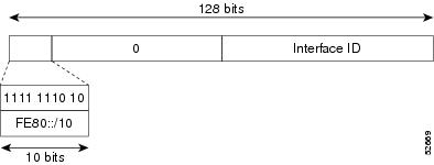
Link-Local Addresses
A link-local address is an IPv6 unicast address that can be automatically configured on any interface using the link-local
prefix FE80::/10 (1111 1110 10) and the interface identifier in the modified EUI-64 format. Link-local addresses are used
in the Neighbor Discovery Protocol (NDP) and the stateless autoconfiguration process. Nodes on a local link can use link-local
addresses to communicate; the nodes do not need globally unique addresses to communicate.
IPv6 routers cannot forward packets that have link-local source or destination addresses to other links.
Figure 2. Link-Local Address Format
IPv4-Compatible IPv6 Addresses
An IPv4-compatible IPv6 address is an IPv6 unicast address that has zeros in the high-order 96 bits of the address and an
IPv4 address in the low-order 32 bits of the address. The format of an IPv4-compatible IPv6 address is 0:0:0:0:0:0:A.B.C.D
or ::A.B.C.D. The entire 128-bit IPv4-compatible IPv6 address is used as the IPv6 address of a node and the IPv4 address embedded
in the low-order 32 bits is used as the IPv4 address of the node. IPv4-compatible IPv6 addresses are assigned to nodes that
support both the IPv4 and IPv6 protocol stacks and are used in automatic tunnels.
Figure 3. IPv4-Compatible IPv6 Address Format
Unique Local Addresses
A unique local address is an IPv6 unicast address that is globally unique and is intended for local communications. It is
not expected to be routable on the global Internet and is routable inside of a limited area, such as a site, and it may be
routed between a limited set of sites. Applications may treat unique local addresses like global scoped addresses.
A unique local address has the following characteristics:
It has a globally unique prefix (it has a high probability of uniqueness).
It has a well-known prefix to allow for easy filtering at site boundaries
It allows sites to be combined or privately interconnected without creating any address conflicts or requiring renumbering
of interfaces that use these prefixes.
It is ISP-independent and can be used for communications inside of a site without having any permanent or intermittent Internet
connectivity.
If it is accidentally leaked outside of a site through routing or the Domain Name Server (DNS), there is no conflict with
any other addresses.
Figure 4. Unique Local Address Structure
Site Local Addresses
Because RFC 3879 deprecates the use of site-local addresses, you should follow the recommendations of unique local addressing
(ULA) in RFC 4193 when you configure private IPv6 addresses.
IPv6 Anycast Addresses
An anycast address is an address that is assigned to a set of interfaces that belong to different nodes. A packet sent to
an anycast address is delivered to the closest interface-as defined by the routing protocols in use-identified by the anycast
address. Anycast addresses are syntactically indistinguishable from unicast addresses because anycast addresses are allocated
from the unicast address space. Assigning a unicast address to more than one interface turns a unicast address into an anycast
address. You must configure the nodes to which the anycast address to recognize that the address is an anycast address.
Note
Anycast addresses can be used only by a router, not a host. Anycast addresses cannot be used as the source address of an
IPv6 packet.
The following figure shows the format of the subnet router anycast address; the address has a prefix concatenated by a series
of zeros (the interface ID). The subnet router anycast address can be used to reach a router on the link that is identified
by the prefix in the subnet router anycast address.
Figure 5. Subnet Router Anycast Address Format
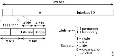
IPv6 Multicast Addresses
An IPv6 multicast address is an IPv6 address that has a prefix of FF00::/8 (1111 1111). An IPv6 multicast address is an identifier
for a set of interfaces that belong to different nodes. A packet sent to a multicast address is delivered to all interfaces
identified by the multicast address. The second octet following the prefix defines the lifetime and scope of the multicast
address. A permanent multicast address has a lifetime parameter equal to 0; a temporary multicast address has a lifetime parameter
equal to 1. A multicast address that has the scope of a node, link, site, or organization, or a global scope, has a scope
parameter of 1, 2, 5, 8, or E, respectively. For example, a multicast address with the prefix FF02::/16 is a permanent multicast
address with a link scope.
Figure 6. IPv6 Multicast Address Format
IPv6 nodes (hosts and routers) are required to join (where received packets are destined for) the following multicast groups:
All-nodes multicast group FF02:0:0:0:0:0:0:1 (the scope is link-local)
Solicited-node multicast group FF02:0:0:0:0:1:FF00:0000/104 for each of its assigned unicast and anycast addresses
IPv6 routers must also join the all-routers multicast group FF02:0:0:0:0:0:0:2 (the scope is link-local).
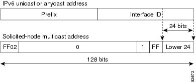
The solicited-node multicast address is a multicast group that corresponds to an IPv6 unicast or anycast address. IPv6 nodes
must join the associated solicited-node multicast group for every unicast and anycast address to which it is assigned. The
IPv6 solicited-node multicast address has the prefix FF02:0:0:0:0:1:FF00:0000/104 concatenated with the 24 low-order bits
of a corresponding IPv6 unicast or anycast address. For example, the solicited-node multicast address that corresponds to
the IPv6 address 2037::01:800:200E:8C6C is FF02::1:FF0E:8C6C. Solicited-node addresses are used in neighbor solicitation messages.
Figure 7. Pv6 Solicited-Node Multicast Address Format
Note
IPv6 has no broadcast addresses. IPv6 multicast addresses are used instead of broadcast addresses.
IPv4 Packet Header
The base IPv4 packet header has 12 fields with a total size of 20 octets (160 bits). The 12 fields may be followed by an
Options field, which is followed by a data portion that is usually the transport-layer packet. The variable length of the
Options field adds to the total size of the IPv4 packet header. The shaded fields of the IPv4 packet header are not included
in the IPv6 packet header.
Figure 8. IPv4 Packet Header Format
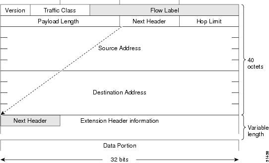
Simplified IPv6 Packet Header
The base IPv6 packet header has 8 fields with a total size of 40 octets (320 bits). Fragmentation is handled by the source
of a packet and checksums at the data link layer and transport layer are used. The User Datagram Protocol (UDP) checksum checks
the integrity of the inner packet and the base IPv6 packet header and Options field are aligned to 64 bits, which can facilitate
the processing of IPv6 packets.
Table 2. Base IPv6 Packet Header Fields
Field
Description
Version
Similar to the Version field in the IPv4 packet header, except that the field lists number 6 for IPv6 instead of number 4
for IPv4.
Traffic Class
Similar to the Type of Service field in the IPv4 packet header. The Traffic Class field tags packets with a traffic class
that is used in differentiated services.
Flow Label
New field in the IPv6 packet header. The Flow Label field tags packets with a specific flow that differentiates the packets
at the network layer.
Payload Length
Similar to the Total Length field in the IPv4 packet header. The Payload Length field indicates the total length of the data
portion of the packet.
Next Header
Similar to the Protocol field in the IPv4 packet header. The value of the Next Header field determines the type of information
that follows the base IPv6 header. The type of information that follows the base IPv6 header can be a transport-layer packet,
for example, a TCP or UDP packet, or an Extension Header.
Hop Limit
Similar to the Time to Live field in the IPv4 packet header. The value of the Hop Limit field specifies the maximum number
of routers that an IPv6 packet can pass through before the packet is considered invalid. Each router decrements the value
by one. Because no checksum is in the IPv6 header, the router can decrement the value without needing to recalculate the checksum,
which saves processing resources.
Source Address
Similar to the Source Address field in the IPv4 packet header, except that the field contains a 128-bit source address for
IPv6 instead of a 32-bit source address for IPv4.
Destination Address
Similar to the Destination Address field in the IPv4 packet header, except that the field contains a 128-bit destination
address for IPv6 instead of a 32-bit destination address for IPv4.
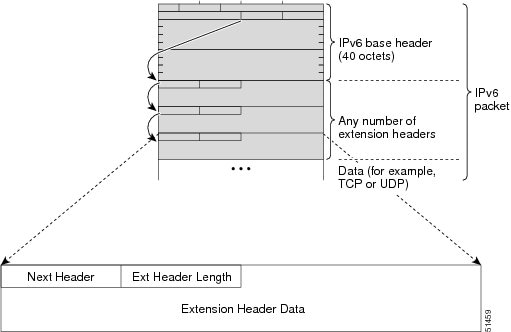
Figure 9. IPv6 Packet Header Format
Optional extension headers and the data portion of the packet are after the eight fields of the base IPv6 packet header.
If present, each extension header is aligned to 64 bits. There is no fixed number of extension headers in an IPv6 packet.
Each extension header is identified by the Next Header field of the previous header. Typically, the final extension header
has a Next Header field of a transport-layer protocol, such as TCP or UDP.
Figure 10. IPv6 Extension Header Format
Table 3. IPv6 Extension Header Types
Header Type
Next Header Value
Description
Hop-by-Hop options header
0
Header that is processed by all hops in the path of a packet. When present, the hop-by-hop options header always follows immediately
after the base IPv6 packet header.
Destination Header Options
60
Header that can follow any hop-by-hop options header. The header is processed at the final destination and at each visited
address specified by a routing header. Alternatively, the destination options header can follow any Encapsulating Security
Payload (ESP) header. The destination options header is processed only at the final destination.
Routing Header
43
Header that is used for source routing.
Fragment Header
44
Header that is used when a source fragments a packet that is larger than the maximum transmission unit (MTU) for the path
between itself and a destination. The Fragment header is used in each fragmented packet.
Upper-Layer Headers
6 (TCP)
17 (UDP)
Headers that are used inside a packet to transport the data. The two main transport protocols are TCP and UDP.
DNS for IPv6
IPv6 supports DNS record types that
are supported in the DNS name-to-address and address-to-name lookup processes.
The DNS record types support IPv6 addresses.
Note
IPv6 also supports the reverse mapping of IPv6 addresses to DNS names.
Table 4. IPv6 DNS Record Types
Record Type
Description
Format
AAAA
Maps a hostname to an IPv6 address. (Equivalent to an A record
in IPv4.)
www.abc.test AAAA 3FFE:YYYY:C18:1::2
PTR
Maps an IPv6 address to a hostname. (Equivalent to a PTR record
in IPv4.)
As in IPv4, you can use path MTU discovery in IPv6 to allow a host to dynamically discover and adjust to differences in the
MTU size of every link along a data path. In IPv6, however, fragmentation is handled by the source of a packet when the path
MTU of one link along a given data path is not large enough to accommodate the size of the packets. Having IPv6 hosts handle
packet fragmentation saves IPv6 router processing resources and helps IPv6 networks run more efficiently. Once the path MTU
is reduced by the arrival of an ICMP Too Big message, Cisco NX-OS retains the lower value. The connection does not increase
the segment size to gauge the throughput.
Note
In IPv6, the minimum link MTU is 1280 octets. We recommend that you use an MTU value of 1500 octets for IPv6 links.
CDP IPv6 Address Support
You can use the Cisco Discovery Protocol (CDP) IPv6 address support for the neighbor information feature to transfer IPv6
addressing information between two Cisco devices. Cisco Discovery Protocol support for IPv6 addresses provides IPv6 information
to network management products and troubleshooting tools.
ICMP for IPv6
You can use ICMP in IPv6 to provide information about the health
of the network. ICMPv6, the version that works with IPv6, reports
errors if packets cannot be processed correctly and sends
informational messages about the status of the network. For
example, if a router cannot forward a packet because it is too
large to be sent out on another network, the router sends out an
ICMPv6 message to the originating host. Additionally, ICMP packets
in IPv6 are used in IPv6 neighbor discovery and path MTU discovery.
The path MTU discovery process ensures that a packet is sent using
the largest possible size that is supported on a specific
route.
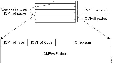
A value of 58 in the Next Header field of the base IPv6 packet
header identifies an IPv6 ICMP packet. The ICMP packet follows all
the extension headers and is the last piece of information in the
IPv6 packet.Within the IPv6 ICMP packets, the ICMPv6 Type and
ICMPv6 Code fields identify IPv6 ICMP packet specifics, such as the
ICMP message type. The value in the Checksum field is computed by
the sender and checked by the receiver from the fields in the IPv6
ICMP packet and the IPv6 pseudo header.
Note
The IPv6 header does not have a checksum. But a checksum on the transport layer can determine if packets have not been delivered
correctly. All checksum calculations that include the IP address in the calculation must be modified for IPv6 to accommodate
the new 128-bit address. A checksum is generated using a pseudo header.
The ICMPv6 Payload field contains error or diagnostic information that relates to IP packet processing.
Figure 11. IPv6 ICMP Packet Header Format
IPv6 Neighbor Discovery
You can use the IPv6 Neighbor Discovery Protocol (NDP) to determine whether a neighboring router is reachable. IPv6 nodes
use neighbor discovery to determine the addresses of nodes on the same network (local link), to find neighboring routers that
can forward their packets, to verify whether neighboring routers are reachable or not, and to detect changes to link-layer
addresses. NDP uses ICMP messages to detect whether packets are sent to neighboring routers that are unreachable.
IPv6 Neighbor Solicitation Message
A node sends a neighbor solicitation message, which has a value of 135 in the Type field of the ICMP packet header, on the
local link when it wants to determine the link-layer address of another node on the same local link. The source address is
the IPv6 address of the node that sends the neighbor solicitation message. The destination address is the solicited-node multicast
address that corresponds to the IPv6 address of the destination node. The neighbor solicitation message also includes the
link-layer address of the source node.
After receiving the neighbor solicitation message, the destination node replies by sending a neighbor advertisement message,
which has a value of 136 in the Type field of the ICMP packet header, on the local link. The source address is the IPv6 address
of the node (the IPv6 address of the node interface that sends the neighbor advertisement message). The destination address
is the IPv6 address of the node that sends the neighbor solicitation message. The data portion includes the link-layer address
of the node that sends the neighbor advertisement message.
After the source node receives the neighbor advertisement, the
source node and destination node can communicate.
Neighbor solicitation messages can verify the reachability of a
neighbor after a node identifies the link-layer address of a
neighbor. When a node wants to verify the reachability of a
neighbor, it uses the destination address in a neighbor
solicitation message as the unicast address of the neighbor.
Neighbor advertisement messages are also sent when there is a
change in the link-layer address of a node on a local link. When
there is a change, the destination address for the neighbor
advertisement is the all-nodes multicast address.
Neighbor unreachability detection identifies the failure of a
neighbor or the failure of the forward path to the neighbor and is
used for all paths between hosts and neighboring nodes (hosts or
routers). Neighbor unreachability detection is performed for
neighbors to which only unicast packets are being sent and is not
performed for neighbors to which multicast packets are being
sent.
A neighbor is considered reachable when a positive
acknowledgment is returned from the neighbor (indicating that
packets previously sent to the neighbor have been received and
processed). A positive acknowledgment-from an upper-layer protocol
(such as TCP)-indicates that a connection is making forward
progress (reaching its destination). If packets are reaching the
peer, they are also reaching the next-hop neighbor of the source.
Forward progress is also a confirmation that the next-hop neighbor
is reachable.
For destinations that are not on the local link, forward
progress implies that the first-hop router is reachable. When
acknowledgments from an upper-layer protocol are not available, a
node probes the neighbor using unicast neighbor solicitation
messages to verify that the forward path is still working. The
return of a solicited neighbor advertisement message from the
neighbor is a positive acknowledgment that the forward path is
still working (neighbor advertisement messages that have the
solicited flag set to a value of 1 are sent only in response to a
neighbor solicitation message). Unsolicited messages confirm only
the one-way path from the source to the destination node; solicited
neighbor advertisement messages indicate that a path is working in
both directions.
Note
A neighbor advertisement message that has the solicited flag set to a value of 0 is not considered as a positive acknowledgment
that the forward path is still working.
Neighbor solicitation messages are also used in the stateless autoconfiguration process to verify the uniqueness of unicast
IPv6 addresses before the addresses are assigned to an interface. Duplicate address detection is performed first on a new,
link-local IPv6 address before the address is assigned to an interface (the new address remains in a tentative state while
duplicate address detection is performed). A node sends a neighbor solicitation message with an unspecified source address
and a tentative link-local address in the body of the message. If another node is already using that address, the node returns
a neighbor advertisement message that contains the tentative link-local address. If another node is simultaneously verifying
the uniqueness of the same address, that node also returns a neighbor solicitation message. If no neighbor advertisement messages
are received in response to the neighbor solicitation message and no neighbor solicitation messages are received from other
nodes that are attempting to verify the same tentative address, the node that sent the original neighbor solicitation message
considers the tentative link-local address to be unique and assigns the address to the interface.
IPv6 Router Advertisement Message
Router advertisement (RA) messages, which have a value of 134 in
the Type field of the ICMP packet header, are periodically sent out
to each configured interface of an IPv6 router. For stateless
autoconfiguration to work properly, the advertised prefix length in
RA messages must always be 64 bits.
The RA messages are sent to the all-nodes multicast address.
Figure 13. Neighbor Discovery—RA Message
RA messages typically include the following information:
One or more onlink IPv6 prefixes that nodes on the local link
can use to automatically configure their IPv6 addresses
Life-time information for each prefix included in the
advertisement
Sets of flags that indicate the type of
autoconfiguration (stateless or stateful) that can be completed
Default router information (whether the router sending
the advertisement should be used as a default router and, if so,
the amount of time in seconds that the router should be used as a
default router)
Additional information for hosts, such as the hop
limit and MTU that a host should use in packets that it
originates
RAs are also sent in response to router solicitation messages.
Router solicitation messages, which have a value of 133 in the Type
field of the ICMP packet header, are sent by hosts at system
startup so that the host can immediately autoconfigure without
needing to wait for the next scheduled RA message. The source
address is usually the unspecified IPv6 address (0:0:0:0:0:0:0:0).
If the host has a configured unicast address, the unicast address
of the interface that sends the router solicitation message is used
as the source address in the message. The destination address is
the all-routers multicast address with a scope of the link. When an
RA is sent in response to a router solicitation, the destination
address in the RA message is the unicast address of the source of
the router solicitation message.
You can configure the following RA message parameters:
The time interval between periodic RA messages
The router life-time value, which indicates the
usefulness of a router as the default router (for use by all nodes
on a given link)
The network prefixes in use on a given link
The time interval between neighbor solicitation
message retransmissions (on a given link)
The amount of time that a node considers a neighbor
reachable (for use by all nodes on a given link)
The configured parameters are specific to an interface. The sending of RA messages (with default values) is automatically
enabled on Ethernet interfaces. For other interface types, you must enter the no ipv6 nd suppress-ra command to send RA messages. You can disable the RA message feature on individual interfaces by entering the ipv6 nd suppress-ra command.
IPv6 Router
Advertisement Options for DNS Configuration
Most of the internet
services are identified by a Domain Name Server (DNS) name. Cisco NX-OS IPv6
Router Advertisement (RA) provides the following two options to allow IPv6
hosts to perform automatic DNS configuration:
Recursive DNS Server (RDNSS)
DNS Search List (DNSSL)
RDNSS contains the address of recursive DNS servers that help in DNS
name resolution in IPv6 hosts. DNS Search List is a list of DNS suffix domain
names used by IPv6 hosts when they perform DNS query searches.
For more information on RA options for DNS configuration, refer IETF RFC
6106.
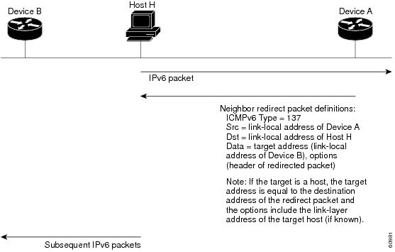
IPv6 Neighbor
Redirect Message
Routers send neighbor redirect
messages to inform hosts of better first-hop nodes on the path to a
destination. A value of 137 in the Type field of the ICMP packet header
identifies an IPv6 neighbor redirect message.
A router must be able to determine the link-local address for each of
its neighboring routers in order to ensure that the target address (the final
destination) in a redirect message identifies the neighbor router by its
link-local address. For static routing, you should specify the address of the
next-hop router using the link-local address of the router. For dynamic
routing, you must configure all IPv6 routing protocols to exchange the
link-local addresses of neighboring routers.
After forwarding a packet, a router sends a redirect message to the
source of the packet under the following circumstances:
The destination address of the packet is not a multicast address.
The packet was not addressed to the router.
The packet is about to be sent out the interface on which it was
received.
The router determines that a better first-hop node for the packet
resides on the same link as the source of the packet.
The source address of the packet is a global IPv6 address of a
neighbor on the same link or a link-local address.
Virtualization Support for IPv6
IPv6 supports virtual routing and forwarding (VRF) instances. VRFs exist within virtual device contexts (VDCs). By default,
Cisco NX-OS places you in the default VDC and default VRF unless you specifically configure another VDC and VRF. For more
information, see the Cisco Nexus 7000 Series NX-OS Virtual Device Context Configuration Guide.
Prerequisites for IPv6
IPv6 has the following prerequisites:
You must be familiar with IPv6 basics such as IPv6
addressing, IPv6 header information, ICMPv6, and the IPv6 Neighbor
Discovery (ND) Protocol.
Ensure that you follow the memory/processing
guidelines when you make a device a dual-stack device
(IPv4/IPv6).
Guidelines and
Limitations for Configuring IPv6
IPv6 has the following
configuration guidelines and limitations:
IPv6 packets are
transparent to Layer 2 LAN switches because the switches do not examine Layer 3
packet information before forwarding IPv6 frames. IPv6 hosts can be directly
attached to Layer 2 LAN switches.
You can configure
multiple IPv6 global addresses within the same prefix on an interface. However,
multiple IPv6 link-local addresses on an interface are not supported.
It supports
contiguous masks only for both IPv4 and IPv6 addresses and does not support
discontiguous masks IPv6 and IPv4 filters.
Each interface
can be configured with a maximum of 255 global IPv6 addresses and a maximum of
255 anycast IPv6 addresses.
Because RFC 3879
deprecates the use of site-local addresses, you should configure private IPv6
addresses according to the recommendations of unique local addressing (ULA) in
RFC 4193.
F2 Series modules
do not support IPv6 tunnels.
On F2 Series
modules, you must disable IGMP optimized multicast flooding (OMF) on any VLANs
that require any IPv6 packet forwarding (unicast or multicast). IPv6 neighbor
discovery functions correctly only in a VLAN with the OMF feature disabled. To
disable OMF, use the
no ip igmp
snooping optimised-multicast-flood command in VLAN configuration
mode. With OMF disabled, unknown IPv4 multicast traffic (as well as all IPv6
multicast traffic) is flooded to all ports in the VLAN. Note that unknown
multicast traffic refers to multicast packets with an active source but no
receivers (and therefore no group forwarding entry in the hardware) in the
ingress VLAN.
IPv6 static route next hop link-local address cannot be configured at any local interface.
Default Settings for IPv6
Parameters
Default
ND reachable time
0 milliseconds
neighbor solicitation retransmit interval
1000 milliseconds
By default, IPv6 source routing is enabled on the switch. To disable IPv6 source routing configure no ipv6 source-route command on the switch.
Configuring IPv6
Configuring IPv6
Addressing
You must configure
an IPv6 address on an interface so that the interface can forward IPv6 traffic.
When you configure a global IPv6 address on an interface, it automatically
configures a link-local address and activates IPv6 for that interface.
Note
Each
interface can be configured with a maximum of 255 global IPv6 addresses and a
maximum of 255 anycast IPv6 addresses.
Before you begin
Ensure that you are
in the correct VDC (or use the
switchto
vdc command).
Specifies an
IPv6 address assigned to the interface and enables IPv6 processing on the
interface.
Entering the
ipv6
address command configures global IPv6 addresses with an interface
identifier (ID) in the low-order 64 bits of the IPv6 address. Only the 64-bit
network prefix for the address needs to be specified; the last 64 bits are
automatically computed from the interface ID.
Entering the
ipv6
address use-link-local-onlycommand configures a link-local address on
the interface that is used instead of the link-local address that is
automatically configured when IPv6 is enabled on the interface.
This command
enables IPv6 processing on an interface without configuring an IPv6 address.
You can configure
IPv6 neighbor discovery on the router. Neighbor Discovery (ND) enables IPv6
nodes and routers to determine the link-layer address of a neighbor on the same
link, find neighboring routers, and keep track of neighbors.
Before you begin
Ensure that you are
in the correct VDC (or use the
switchto
vdc command).
Specifies an
IPv6 address assigned to the interface and enables IPv6 processing on the
interface.
hop-limithop-limit— Advertises the hop limit in IPv6
neighbor discovery packets. The range is from 0 to 255.
managed-config-flag— Advertises in ICMPv6
router-advertisement messages to use stateful address auto-configuration to
obtain address information.
mtumtu—Advertises the maximum transmission unit (MTU)
in ICMPv6 router-advertisement messages on this link. The range is from 1280 to
65535 bytes.
ns-intervalinterval—Configures the retransmission interval
between IPv6 neighbor solicitation messages. The range is from 1000 to 3600000
milliseconds.
other-config-flag—Indicates in ICMPv6
router-advertisement messages that hosts use stateful auto-configuration to
obtain nonaddress related information.
prefix—Advertises the IPv6 prefix in the
router-advertisement messages.
ra-intervalinterval—Configures the interval between sending
ICMPv6 router-advertisement messages. The range is from 4 to 1800 seconds.
ra-lifetimelifetime—Advertises the lifetime of a default
router in ICMPv6 router-advertisement messages. The range is from 0 to 9000
seconds.
reachable-timetime—Advertises the time when a node considers a
neighbor up after receiving a reachability confirmation in ICMPv6
router-advertisement messages. The range is from 0 to 9000 seconds.
retrans-timertime—Advertises the time between
neighbor-solicitation messages in ICMPv6 router-advertisement messages. The
range is from 0 to 9000 seconds.
Advertises the
IPv6 prefix in the router advertisement messages.
valid-lifetime—The
amount of time (in seconds) that the specified IPv6 prefix is advertised as
being valid.
infinite—Specifies that the valid lifetime is
infinite.
no-advertise—Specifies that the prefix is not
advertised.
preferred-lifetime—The amount of time (in seconds)
that the specified IPv6 prefix is advertised as being preferred.
no-autoconfig—Indicates to hosts on the local link
that the specified prefix cannot be used for IPv6 autoconfiguration. The prefix
will be advertised with the A-bit clear.
no-onlink—Configures the specified prefix as not
on-link. The prefix will be advertised with the L-bit clear.
off-link—Configures the specified prefix as
off-link. The prefix will be advertised with the L-bit clear. The prefix will
not be inserted into the routing table as a connected prefix. If the prefix is
already present in the routing table as a connected prefix (for example,
because the prefix was also configured using the
ipv6 address command), it will be removed.
Step 5
(Optional) switch(config-if)#
show ip nd
interface
(Optional)
Displays
interfaces configured for IPv6 neighbor discovery.
This example shows
how to display an IPv6 interface:
switch# configure terminal
switch(config)# show ipv6 nd interface ethernet 3/1

ICMPv6 ND Interfaces for VRF "default"
Ethernet3/1, Interface status: protocol-down/link-down/admin-down
IPv6 address: 0dc3:0dc3:0000:0000:0218:baff:fed8:239d
ICMPv6 active timers:
Last Neighbor-Solicitation sent: never
Last Neighbor-Advertisement sent: never
Last Router-Advertisement sent:never
Next Router-Advertisement sent in: 0.000000
Router-Advertisement parameters:
Periodic interval: 200 to 600 seconds
Send "Managed Address Configuration" flag: false
Send "Other Stateful Configuration" flag: false
Send "Current Hop Limit" field: 64
Send "MTU" option value: 1500
Send "Router Lifetime" field: 1800 secs
Send "Reachable Time" field: 10 ms
Send "Retrans Timer" field: 0 ms
Neighbor-Solicitation parameters:
NS retransmit interval: 1000 ms
ICMPv6 error message parameters:
Send redirects: false
Send unreachables: false
This example shows
how to include the IPv6 prefix 2001:0DB8::/35 in router advertisements that are
sent out Ethernet interface 0/0 with a valid lifetime of 1000 seconds and a
preferred lifetime of 900 seconds:
Configures the maximum number of entries in the neighbor
adjacency table. The range is from 1 to 409600.
The
syslog keyword configures the
number of system logs per second. The range is from 1 to 1000.
If you configure a limit for IPv6 neighbor discovery
entries, system logs appear if you try to add an adjacency after reaching the
configured limit.
Note
You cannot unconfigure the cache limit until the total
number of current adjacencies is less than 131,072.
ipv6 nd dad attemptsnumber
Sets the number of consecutive neighbor solicitation
messages that the device sends from the IPv6 interface for duplicate address
detection (DAD) validation. The default value is 1 attempt.
ipv6 nd fast-path
Improves the performance of glean packets by reducing the
processing of the packets in the supervisor. It applies to glean packets where
the destination IP address is part of the same subnet and does not apply to
packets where the destination IP address is in a different subnet. The default
is enabled.
ipv6 nd hop-limit
Configures the maximum number of hops used in router
advertisements and all IPv6 packets that are originated by the router.
ipv6 nd
managed-config-flag
Sets the managed address configuration flag in IPv6 router
advertisements.
ipv6 nd mtu
Sets the maximum transmission unit (MTU) size of IPv6
packets sent on an interface.
ipv6 nd
ns-interval
Configures the interval between IPv6 neighbor solicitation
retransmissions on an interface.
ipv6 nd
other-config-flag
Configures the other stateful configuration flag in IPv6
router advertisements.
ipv6 nd
ra-interval
Configures the interval between IPv6 router advertisement
(RA) transmissions on an interface.
ipv6 nd
ra-lifetime
Configures the router lifetime value in IPv6 router
advertisements on an interface.
ipv6 nd
reachable-time
Configures the amount of time that a remote IPv6 node is
considered reachable after some reachability confirmation event has occurred.
ipv6 nd redirects
Enables ICMPv6 redirect messages to be sent.
ipv6 nd
retrans-timer
Configures the advertised time between neighbor solicitation
messages in router advertisements.
ipv6 nd
suppress-ra
Suppresses IPv6 router advertisement transmissions on a LAN
interface.
Configuring
Recursive DNS Server (RDNSS)
You can configure up
to eight DNS servers to advertise with Router Advertisement. You can also
remove one or more DNS servers from the advertising list by using the
no form of the
command.
Before you begin
Ensure that you are
in the correct VDC (or use the
switchto
vdc command).
Procedure
Command or Action
Purpose
Step 1
switch#
configure
terminal
Enters the
global configuration mode.
Step 2
switch(config)#interface ethernetnumber
Enters interface
configuration mode.
Step 3
switch(config-if)#
ipv6 nd ra dns serveripv6-addr [
rdnss-life |
infinite]
sequencesequence-num
Configures the
recursive DNS server. You can specify the life time and the sequence of the
server.
Step 4
switch(config-if)#
show ipv6 nd ra dns
server [
interfaceinterface ]
(Optional)
Displays the configured RDNSS list.
Step 5
switch(config-if)#
ipv6 nd ra dns server
suppress
(Optional)
Disables the configured server list.
Step 6
switch(config-if)#
no ipv6 nd ra dns server
ipv6-addr [
rdnss-life |
infinite]
sequencesequence-num
Removes a server
from the RDNSS list.
Example
The following
example shows how to configure Recursive DNS Server list on Ethernet 3/3 and
verify the same.
switch# configure terminal
switch(config)# interface ethernet 3/3
switch(config-if)# ipv6 nd ra dns server 1::1 1000 sequence 0
switch(config-if)# ipv6 nd ra dns server 2::1 infinite sequence 1

switch(config)# show ipv6 nd ra dns server

Recursive DNS Server List on: mgmt0
Suppress DNS Server List: No
Recursive DNS Server List on: Ethernet3/3
  Suppress DNS Server List: No
  DNS Server 1: 1::1 Lifetime:1000 seconds Sequence:0
  DNS Server 2: 2::1 Infinite Sequence:1
Configuring DNS
Search List (DNSSL)
You can configure up
to eight DNS search lists to advertise with Router Advertisement. You can also
remove one or more DNS search lists from the advertising list by using the
no form of the
command.
Before you begin
Ensure that you are
in the correct VDC (or use the
switchto
vdc command).
Procedure
Command or Action
Purpose
Step 1
switch#
configure
terminal
Enters the
global configuration mode.
Step 2
switch(config)#interface ethernetnumber
Enters interface
configuration mode.
Step 3
switch(config-if)#
ipv6 nd ra dns
search-listlist [
dnssl-life |
infinite]
sequencesequence-num
Configures the
DNS search list. You can specify the life time and the sequence of the search
list.
Step 4
switch(config-if)#
show ipv6 nd ra dns
search-list [
interfaceinterface ]
(Optional)
Displays the configured DNS search list.
Step 5
switch(config-if)#
ipv6 nd ra dns search-list
suppress
(Optional)
Disables the configured search list.
Step 6
switch(config-if)#
no ipv6 nd ra dns search-list
list [
dnssl-life |
infinite]
sequencesequence-num
(Optional)
Removes a search list from the RA.
Example
The following
example shows how to configure DNS Search list on Ethernet 3/3 and verify the
same.
switch# configure terminal
switch(config)# interface ethernet 3/3
switch(config-if)# ipv6 nd ra dns search-list cisco.com 100 sequence 1
switch(config-if)# ipv6 nd ra dns search-list ind.cisco.com 100 sequence 2

switch(config)# show ipv6 nd ra dns search-list

DNS Search List on: mgmt0
Suppress DNS Search List: No
 DNS Search List on: Ethernet3/3
  Suppress DNS Search List: No
  DNS Server 1:cisco.com 100 Sequence:1
  DNS Server 2:ind.cisco.com 100 Sequence:2
Configuring IPv6 Packet Verification
Cisco NX-OS supports an Intrusion Detection System (IDS) that checks for IPv6 packet verification. You can enable or disable
these IDS checks.
Procedure
Command or Action
Purpose
Step 1
switch# configure terminal
Enters global configuration mode.
Step 2
switch(config)# hardware ip verify address {destination zero | identical | reserved | source multicast}
Performs the following IDS checks on the IPv6 address:
destination zero—Drops IPv6 packets if the destination IP address is ::.
identical—Drops IPv6 packets if the source IPv6 address is identical to the destination IPv6 address.
reserved—Drops IPv6 packets if the IPv6 address is ::1.
source multicast—Drops IPv6 packets if the IPv6 source address is in the FF00::/8 range (multicast).
Step 3
switch(config)# hardware ip verify length {consistent | maximum {max-frag | max-tcp | udp}}
Performs the following IDS checks on the IPv6 address:
consistent—Drops IPv6 packets where the Ethernet frame size is greater than or equal to the IPv6 packet length plus the Ethernet
header.
maximum max-frag—Drops IPv6 packets if the formula (IPv6 Payload Length - IPv6 Extension Header Bytes) + (Fragment Offset
* 8) is greater than 65536..
maximum max-tcp—Drops IPv6 packets if the TCP length is greater than the IP payload length.
maximum max-udp—Drops IPv6 packets if the TCP length is less than the UDP packet length.
For more information related to IP CLI commands, see the Cisco Nexus 7000 Series NX-OS Unicast Routing Command Reference.
Standards for IPv6
No new or modified standards are supported by this feature, and support for existing standards has not been modified by this
feature.
Feature History for
IPv6
This table includes only the updates for those releases that have resulted in additions or changes to the feature.
Table 5. Feature History
for IPv6
Feature Name
Release
Feature Information
Duplicate
address detection
6.2(2)
Added the
ability to set the number of consecutive neighbor solicitation messages that
the device sends from the IPv6 interface.
Glean
optimization
6.2(2)
Added the
fast-path
keyword to the ipv6
nd
command to improve the performance of glean packets
by reducing the processing of the packets in the supervisor.
IPv6
6.2(2)
Added the
ability to configure the maximum number of neighbor discovery entries in the
neighbor adjacency table.
IPv6
6.0(1)
Updated for
F2 Series modules.
IPv6
5.0(2)
Added
support for IPv6 path MTU discovery.
IPv6
4.1(3)
Changed
platform {ip |
ipv6}
verify command to the
hardware {ip |
ipv6}
verify command.


 Feedback