Cisco DCNM Web Client Online Help, 10.4(2) Release
Bias-Free Language
The documentation set for this product strives to use bias-free language. For the purposes of this documentation set, bias-free is defined as language that does not imply discrimination based on age, disability, gender, racial identity, ethnic identity, sexual orientation, socioeconomic status, and intersectionality. Exceptions may be present in the documentation due to language that is hardcoded in the user interfaces of the product software, language used based on RFP documentation, or language that is used by a referenced third-party product. Learn more about how Cisco is using Inclusive Language.
- Updated:
- February 6, 2018
Chapter: Border Provisioning Use Case in VXLAN BGP EVPN Fabrics - VRF Lite
Border
Provisioning Use Case in VXLAN BGP EVPN Fabrics - VRF Lite
- Prerequisites
- Sample Scenario
- VRF Lite Inter-Fabric Configuration
- Deploying VRF Instances on Border Leafs
- Undeploying VRF Instances on the Border Leafs
- Additional References
- Appendix
Prerequisites
-
The DCNM version required to support this feature is 10.4(2).
-
The VRF Lite feature requires Cisco Nexus 9000 Series NX-OS Release 7.0(3)I6(2) or later.
-
Familiarity with VXLAN BGP EVPN data center fabric architecture and top-down based LAN fabric provisioning through the DCNM.
-
Fully configured VXLAN BGP EVPN fabrics including underlay and overlay configurations on the various leaf and spine devices.
-
VXLAN BGP EVPN fabrics (and their interconnection) can be configured manually or using DCNM. This document explains the process to connect the fabrics through DCNM. So, you should know how to configure and deploy a VXLAN BGP EVPN fabric through DCNM. For more details, see the LAN Fabric Provisioning section under the Configure chapter in Cisco DCNM Web Client Online Help, 10.4(2) Release.
-
 Note | For an explanation on the VRF Lite feature, see the Cisco Programmable Fabric with VXLAN BGP EVPN Configuration Guide document. |
Sample Scenario
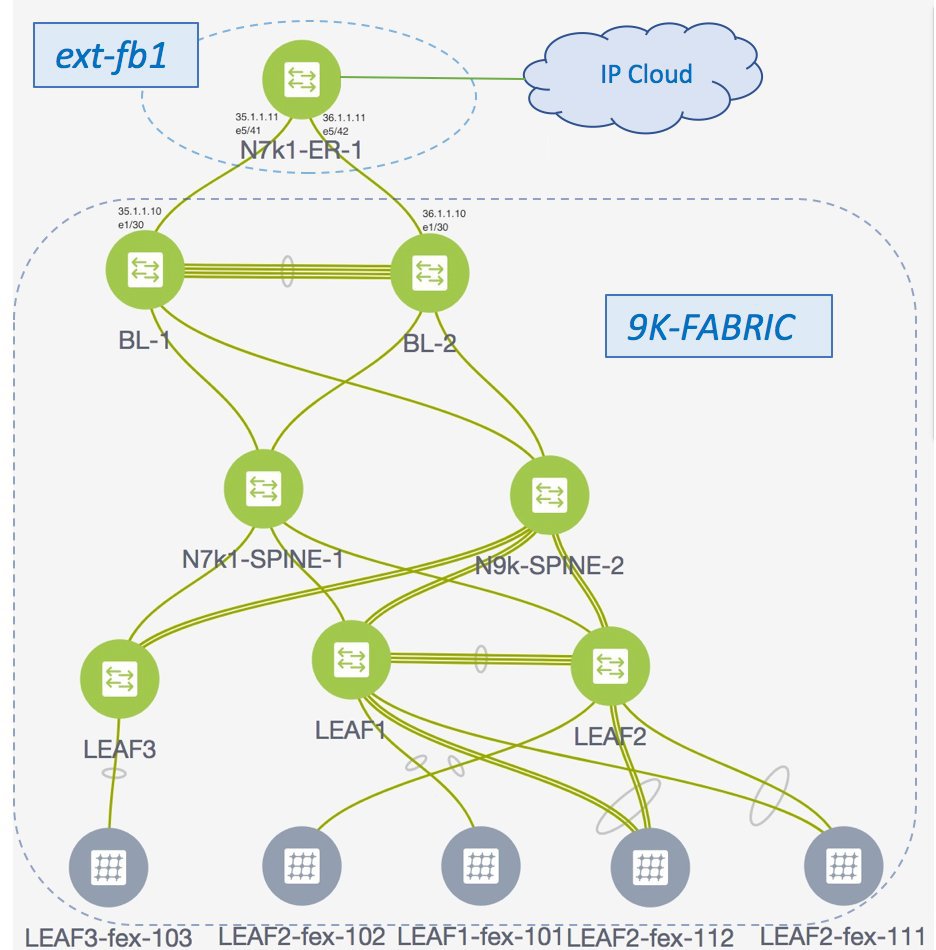
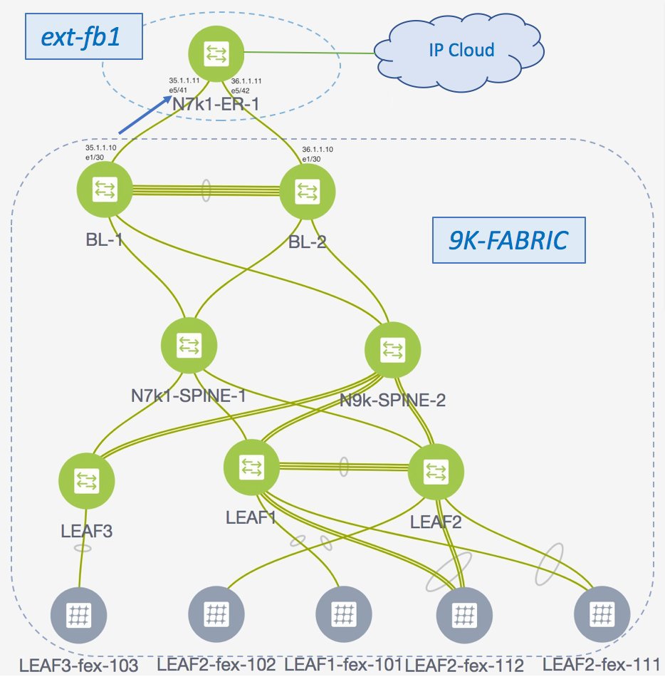
The VRF Lite feature is explained through an example scenario. Consider a VXLAN BGP EVPN fabric, 9K-FABRIC, where the border devices are connected through an edge router to a shared IP core. This document will show you how to enable Layer 3 traffic between hosts in the two fabrics.
Note | In the IP core scenario, DCNM allows provisioning for fabric switches and the border devices. The Edge Router (ER) connected to the border devices needs to be manually configured (in 9K-FABRIC, the edge router N7k1-ER1 [or ER1] is connected to BL1 and BL2). Appropriate CLI templates can also be employed to deploy this configuration on the Cisco Nexus 7000 Series edge devices using DCNM. In the B2B setup, the border leafs on both fabrics can be configured through DCNM. |
Network configurations for the fabric is provisioned through DCNM. For external Layer 3 reachability from hosts connected to leaf switches within the fabric, border devices need to be provisioned with the appropriate VRF configuration. Multiple border devices in the fabric ensure redundancy in the case of failures as well as effective load distribution.
Note | The DCI functions VRF Lite and VRF Lite + Multi-Site are in the scope of this document, but MPLS L3VPN and LISP technologies are not in the scope of this document. |
VRF Lite—This requires setting up the border leaf configuration for enabling the VRF Lite feature by establishing eBGP peering from the border leaf to appropriate external devices, either ERs or border leafs in other fabrics. In this context, border leafs are special devices that allow clear control and data plane segregation from one site to another while allowing for policy enforcement points for any inter-fabric traffic.
-
Inter-Fabric Connect—Top-Down deployment for the VRF Lite feature configures route maps and an eBGP session in the default VRF through an interface (parent interface) connected to the ER. This is a one-time setup for each ER connected to a border leaf.
-
VRF Extensions—For each VRF that is to be extended, a unique sub interface towards the ER and an eBGP session through this sub interface is configured on the border leaf. This is a per-VRF configuration. For a B2B scenario, VRF extension configurations on all border leafs can be deployed through DCNM itself. For the IP core setup, the corresponding configurations have to be manually enabled on the ERs.
Note | VRF extensions on a vPC setup of a pair of border leafs have to be enabled on both the vPC peers. DCNM does not allow you to enable extensions on a single vPC switch. |
-
VRF Lite inter-fabric configurations on the border leafs (BL-1, BL-2)
-
VRF Lite function on BL-1 and BL-2, the vPC pair of border leafs in 9K-FABRIC that are directly connected to ER-1.
-
Configurations on edge routers ER-1 and ER-2 - These configurations are not in the scope of DCNM provisioning and this document. It is mentioned here for completeness and sample configurations are provided in the Appendix section. Again, as mentioned earlier, appropriate CLI templates can be employed to provision the edge router if it is a Nexus device.
-
-
Deploying VRF instances on the border leafs (BL-1, BL-2)
For this example, multiple VRFs will be configured on the vPC pair of border leafs in 9K-FABRIC.
After successful VRF Lite deployment at the border leaf and on the edge routers, traffic will flow between them.
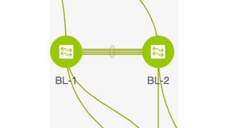
Note | In the DCNM topology view, the lines connecting devices managed by DCNM (for example, BL-1 to N7k1-SPINE-1) symbolize a physical cable connection. They do not indicate that the connection is functional and traffic flows between them. |
To start off with, let us consider VRF Lite provisioning on border leafs BL-1 and BL-2 through DCNM Top-Down LAN Fabric Provisioning.
VRF Lite Inter-Fabric Configuration
Prerequisite Configuration for VRF Lite Configuration
-
Setting the Leaf role to Border Leaf— By default a device will be treated as a leaf switch. You need to change its role to that of a border leaf.
To update the switch role, login to DCNM, and click Topology from the main menu at the left part of the screen. In the Topology screen, from the Scope drop down box, select the fabric and click on the BL-1. A screen pops up with the switch information.
Change the entry from Leaf to Border Leaf as shown in the image.
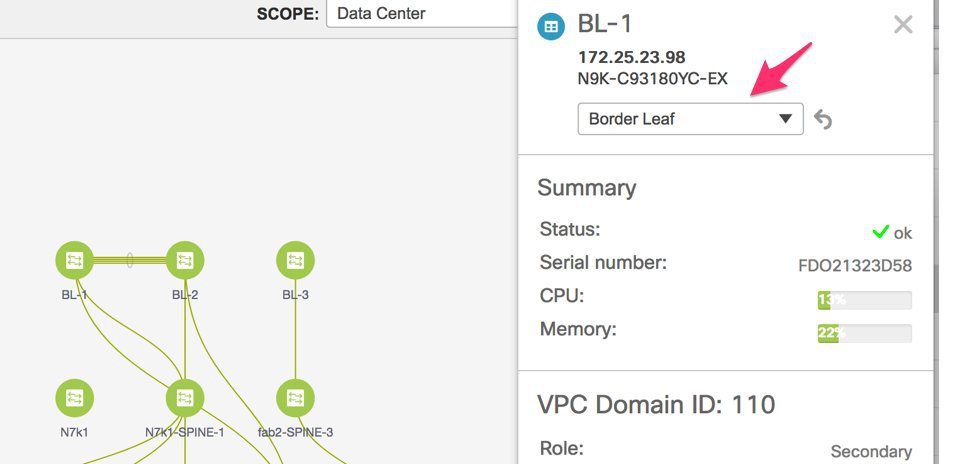
This is required for configuring the VRF Lite feature through the DCNM GUI. After completing the VRF Lite specific prerequisites, start DCNM VRF Lite configuration on BL-1 with extensions to the edge router ER-1.
VRF Lite Inter-Fabric Configuration (on BL-1 towards ER-1 in 9K-FABRIC)
From the Cisco DCNM Web Client, choose Configure > LAN Fabric Provisioning > Network Deployment. The LAN Fabric Provisioning page appears.
Click Continue. The Select a Fabric page comes up.
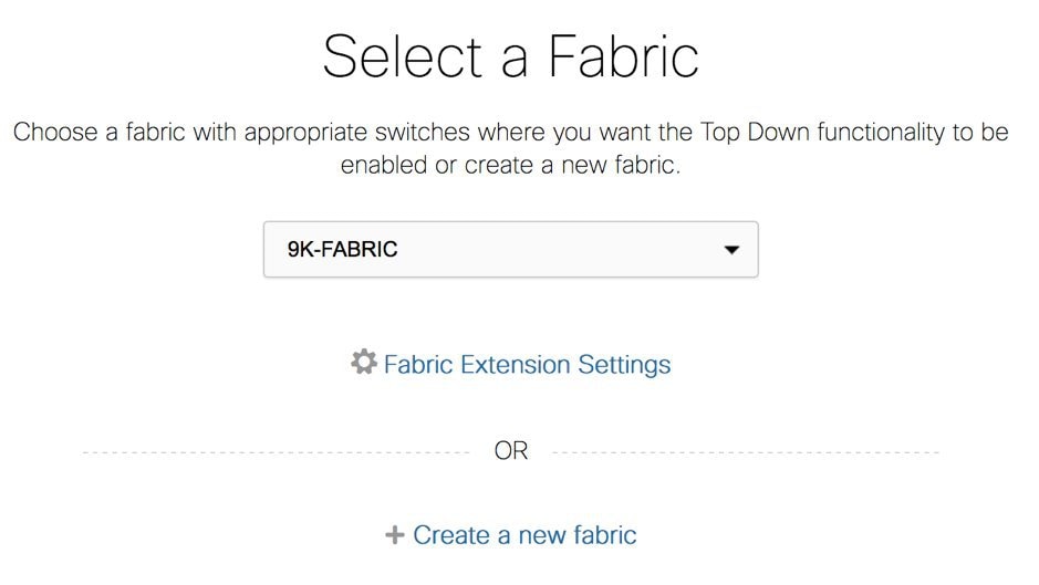
Select 9K-FABRIC from the drop-down box since you are configuring border leaf BL-1 in the fabric 9K-FABRIC.
In the same page, click Fabric Extension Settings since the purpose of this task is to allow 9K-FABRIC to communicate to external fabrics through ER-1 and ER-2. The Fabric Extension screen comes up.

The Inter-Fabric Connections section lists previously created external connections from the border leafs in 9K-FABRIC. This section is empty as this is the first time you are adding an external connection. Each row represents a physical or logical connection between a border leaf in 9K-FABRIC and an external device in another fabric. For each connection, the source fabric, source device, source interface, destination fabric, destination device, and destination interface are listed along with the type of external connectivity.
To extend the fabric through VRF-Lite, you should first create an extension.
- Extension from BL-1 to ER-1
- VRF Lite Inter-Fabric Configuration (on BL-2 towards ER-1 in 9K-FABRIC)
- Edge Router Configurations
Extension from BL-1 to ER-1
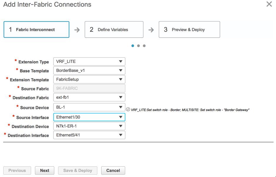
Click on the + icon (at the top left part of the screen) to add a new external connection. The Add Inter-Fabric Connection screen appears.
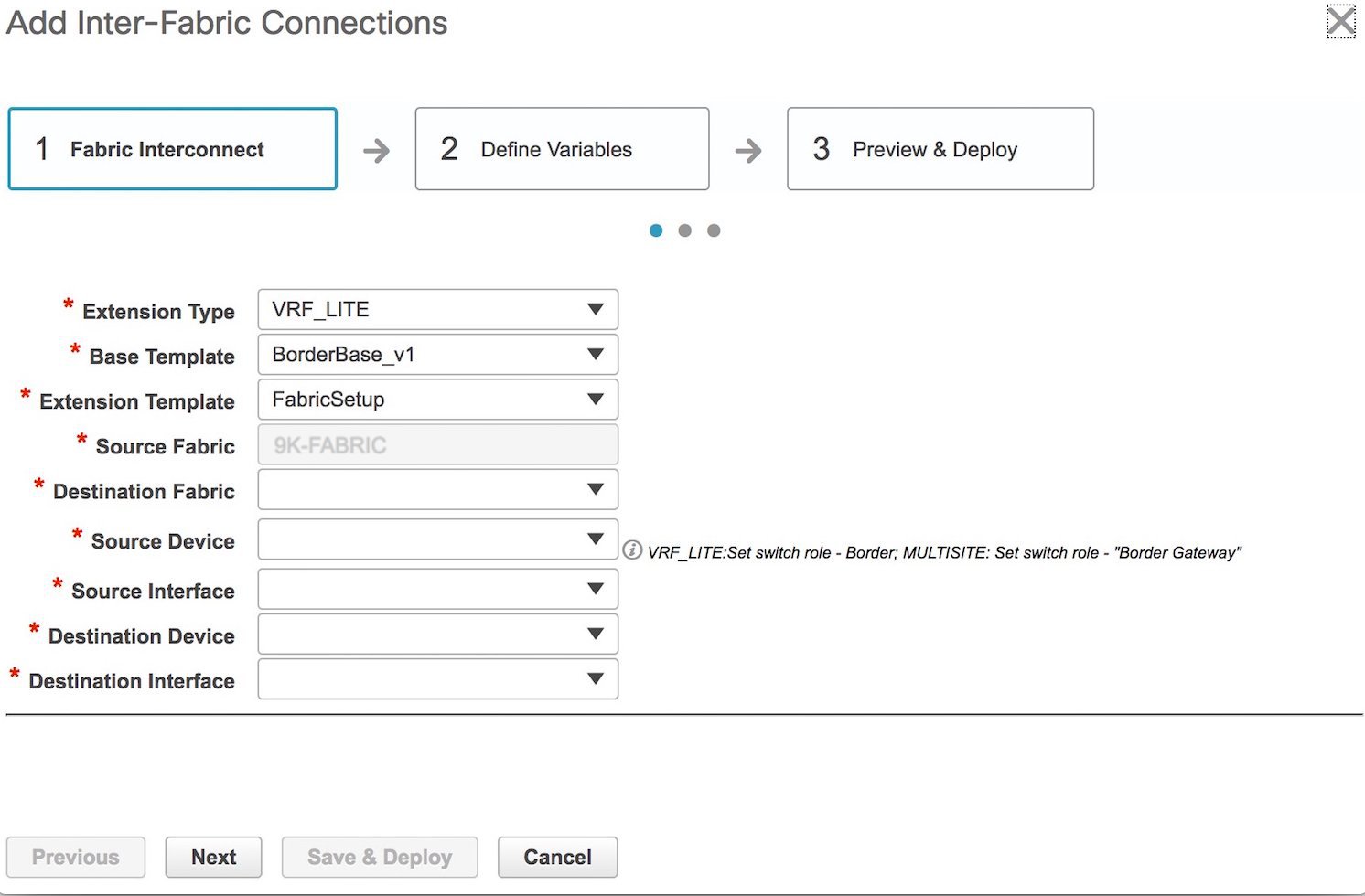
By default, VRF_LITE is populated in the Extension Type field. Since the inter-fabric extension is through VRF Lite, retain this entry.
Base Template—By default, the BorderBase_v1 base template is populated. This template represents a one-time configuration pushed to the border leaf BL-1.
Extension Template—FabricSetup, as the name indicates, represents the template that outputs the configuration required to setup the inter-fabric connection. As opposed to the configuration represented by the Base Template that is applied only once per border leaf, the Extension Template generated configuration is executed once for every inter-fabric connection.
These templates are auto-populated with corresponding pre-packaged default templates based on your selection.
Source Fabric—This field is pre-populated with 9K-FABRIC since the VRF Lite connection is between BL-1 in 9K-FABRIC and ER-1 in the ext-fb1 fabric.
Destination Fabric—Choose ext-fb1.
Source Device and Source Interface—Choose BL-1 as the source device and an Ethernet interface that needs to be connected to ER-1.
Destination Device and Destination Interface—Choose ER-1 as the destination device and the Ethernet interface that connects to the border leaf BL-1.
Note that based on the selection of the source device and source interface, the destination information will be auto-populated based on CDP information if available. There is extra validation performed to ensure that the destination external device is indeed part of the destination fabric.
After filling up the Fabric Interconnect section, the screen looks like this.
Click Next to go to the Define Variables section.

IF_NAME—In this field, the interface name is auto-populated from the previous step.
Interface IP_MASK—Fill up this field with the IP address of the BL-1 interface that connects to ER-1.
NEIGHBOR_IP—Fill up this field with the IP address of the ER-1 interface that connects to BL-1.
NEIGHBOR_ASN—In this field, the AS number of ER-1 will be auto-populated.
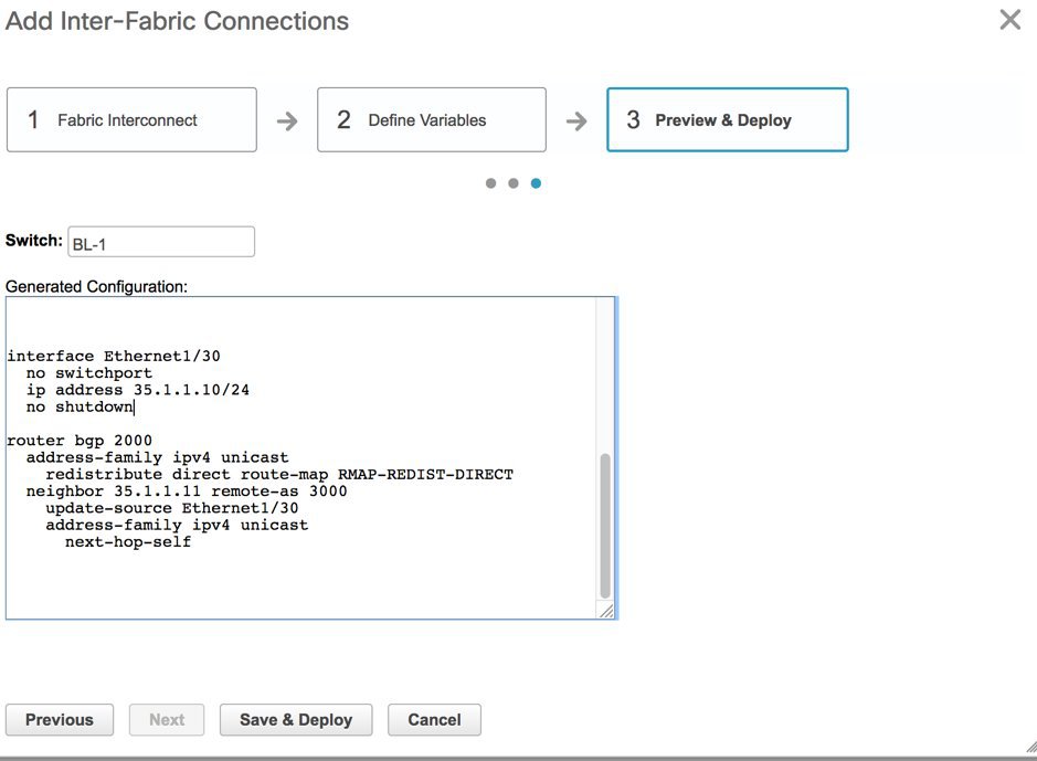
Now that all the information is filled in, click Next to go to the Preview and Deploy section. The two sections of the screen are shown in the 2 images:

Note | In an Inter-Fabric connection, if one border leaf is connected to more than one ER or border leaf, the prefix-list and route map configurations are pushed only for the first fabric extension instance. Similarly when deleting fabric extension instances on a border leaf, the global configurations (prefix-list and route-maps) are removed from the border leaf only after the last fabric extension instance is deleted. |
In this screen, you can preview the configuration that will be deployed to BL-1. Note that no configuration will be pushed to the external device (also known as edge router) itself.
A one-time configuration of route maps along with the parent interface connection is displayed. Also, you can see that BGP peering information in the default routing table is configured for BL-1. The corresponding BGP configurations should be enabled manually on ER-1.
Click Save and Deploy to complete the task. This results in the configuration getting pushed to BL-1. The external connection will appear in the Fabric Extension screen.
At this stage, an extension is enabled from BL-1 to ER-1. Next, you need to enable an extension from BL-2 to ER-1 too, since BL-1 and BL-2 form a vPC border leaf pair.
VRF Lite Inter-Fabric Configuration (on BL-2 towards ER-1 in 9K-FABRIC)
As described in the previous section, enable an extension from BL-2 to ER-1. After configurations are pushed to BL-2, an extension will be enabled from BL-2 to ER-1, as shown in the screen shot.

A preview of the configurations on BL-2 is given in these 2 screen shots.


Edge Router Configurations
Apart from the DCNM provisioning on the border leafs in the two fabrics, you should also enable appropriate configurations on ER-1 for connectivity between the edge router and the border leafs. Sample ER-1 configuration is provided in the Appendix section for your reference.
What to do next—As noted earlier, the end-to-end VRF-Lite configurations through DCNM Top-Down provisioning includes these 2 steps:
At this stage, the first step explanation is complete. The next section explains how VRF extension configuration is pushed to the border leafs.
Deploying VRF Instances on Border Leafs
Before you begin—In this scenario, we will deploy three VRF instances, MyVRF-50016, MyVRF-50018, and MyVRF-50019 on the border leafs BL-1 and BL-2 in 9K-FABRIC. You should ensure that you have already deployed the corresponding network(s) on the fabric's leaf switches.
After deploying one network on the leaf switches, you will have to deploy the associated VRF on the border leafs so that the network(s) can be extended from/to the 9K-FABRIC. To know how to create a new fabric, network, and VRF, see LAN Fabric Provisioning section in the DCNM user guide.
Note | VRF extension on vPC switch pairs can be either deployed or undeployed together on both the peers. |
In the Select a Fabric page, click the Continue button at the top right part of the screen.
(After VRF Lite extensions are created, the DCNM GUI automatically takes you to the Select a Fabric page).
Ensure that you select 9K-FABRIC in the drop-down box and click Continue (at the top right part of the screen). After clicking Continue, the Networks page comes up.
Click on VRF View. The VRFs page comes up.
We will deploy 3 new VRF instances MyVRF-50016, MyVRF-50018, and MyVRF-50019 on the border leafs. To do that, select the checkboxes (in the extreme left column).

Click the Continue button at the top right part of the screen. The VRF Deployment page (Topology View) comes up. You can deploy VRFs on multiple switches simultaneously, but with the same role. So, deploy the selected VRFs on the border leafs.
Note | In the image, you can see that the VRF instances are deployed on the leaf switches (green color indicates deployed status). Note that the color code, and hence the deployment state on switches is contextual and specific to the selection. In this scenario, the deployed state only depicts that the 3 selected VRFs are deployed on leaf switches LEAF3, LEAF1 and LEAF2. It does not display information about other VRF deployment instances, if any. |

Select the multi-select check box at the bottom of the panel of options available (Step 1 in the image) at the right part of the page.
Then, click your mouse (or track pad) and drag the cursor across BL-1 and BL-2 (Step 2 in the image). Note that this is a vPC switch pair of border leafs.
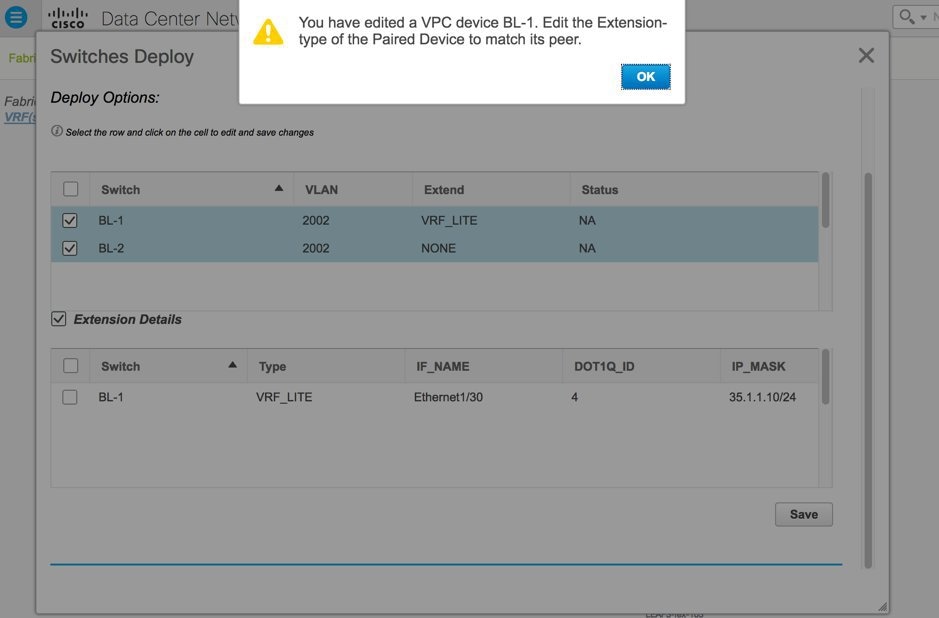
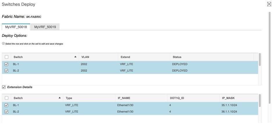
Immediately, the Switches Deploy screen (for VRFs) appears.
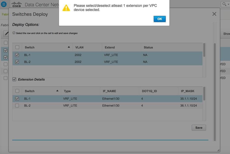
Note | For VRF extension on vPC switches, error messages will be displayed if only one border leaf is selected for VRF Lite extension, or if both the switches are selected for extension but only one (on no) border leaf extension is selected with extension details. Error messages: |
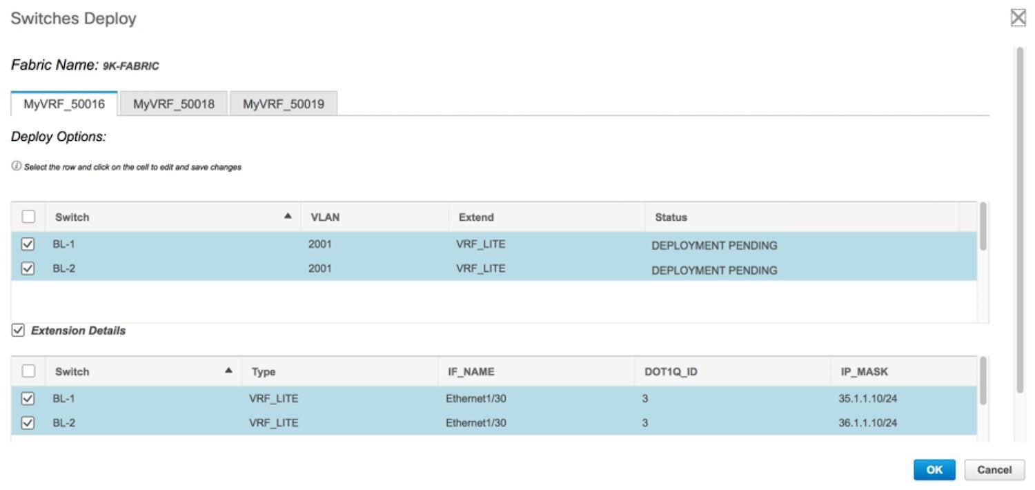
In the VRF extension on vPC switch pairs scenario, a tab is displayed for each VRF.
Click the checkbox next to the Switch column. Both the border leaf check boxes will be selected automatically and the Extension Details section will appear at the bottom part of the screen.
In the Extension Details section, select the Switch checkbox (or ensure that you select the check box in each row). This is how the screen looks when you select both the switches and the Extension Details section.
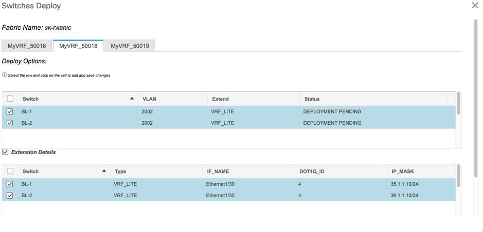
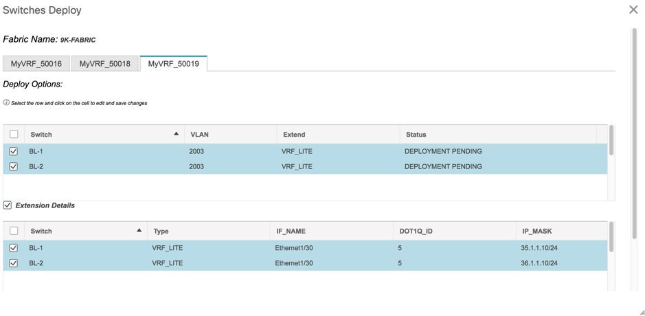
Now, select the MyVRF_50018 and MyVRF_50019 and similarly update relevant parameters.
Click the Save button at the bottom right part of the Switches Deploy screen to save all VRFs' configurations on the selected switches. The VRF Deployment screen (Topology view) appears.
BL-1 and BL-2 icons will be displayed in blue color, indicating that a deployment is pending. If you want to check your configurations, click on the Preview (eye) icon.


You can select a switch and a VRF to view corresponding configurations. Configuration details of MyVRF_5016 that is pushed to BL-1 are included in the Appendix section.
After you verify that the configurations that are generated from the profiles are correct for the selected switches, click the Deploy button (on the top right part of the Topology View screen) to deploy the MyVRF_50016, MyVRF_50018, and MyVRF_50019 VRF configurations on BL-1 and BL-2.
DCNM shows the deployment status in the topology by highlighting the switch icons with different colors, yellow for In Progress, green for Deployed, and red for Error status.
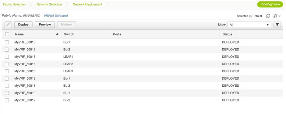
From the snapshot, you can see that the MyVRF_50016, MyVRF_50018, and MyVRF_50019 VRF configurations have been implemented on the vPC border leafs of the 9K-FABRIC. You can also click the Detailed View option to see the status.
After configurations in 9K-FABRIC are complete, you should enable configurations in Fabric2 too.
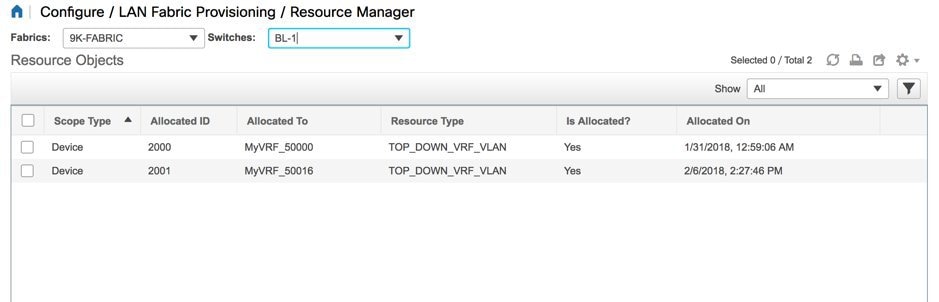
Resource Manager
Resource Manager gives information of all the resources allocated/deployed on each device per fabric. This includes the network VLANs, VRF VLANs, and the sub interface dot1q identifiers employed for the VRF Lite extension. Once a VRF is undeployed, the associated resources on the Resource Manager will be unallocated/updated immediately.
To access the Resource Manager page, click Configure > LAN Fabric Provisioning > Resource Manager
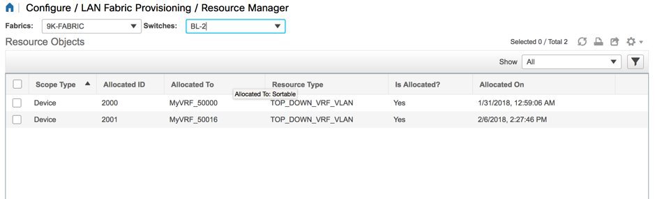
As we can see in the screenshot below, after deploying VRF instances MyVRF_50016, MyVRF_50018 and MyVRF_50019 on the vPC border leafs, the Resource Manager has the associated VLAN-VRF mapping displayed.
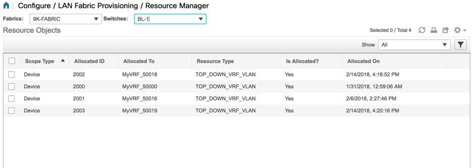
The VRF instances MyVRF_50016, MyVRF_50018, and MyVRF_50019 are deployed on BL-1, with their corresponding VLANs 2001, 2002, and 2003.
Undeploying VRF Instances on the Border Leafs
VRFs can be deployed/undeployed on the border leafs. The following steps will demonstrate undeployment of VRFs on the vPC border leafs.
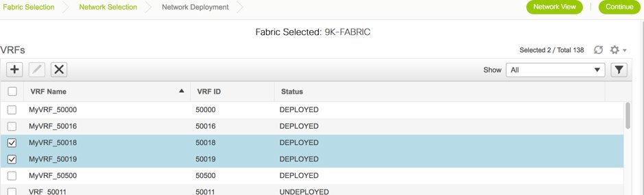
For 9K-FABRIC, navigate to the Networks page and click VRF View. The VRFs page will be displayed.
Select MyVRF-50018 and MyVRF-50019 and click Continue.
The Topology View page is displayed. Follow similar steps as described in the Deploying VRFs section on the vPC border leafs.
Select BL-1 and BL-2 switches in the topology page. The Switches Deploy screen will be displayed.
A tab is displayed for each VRF. MyVRF_50018 is currently selected in the below screenshot.
Double click the checkbox next to the Switch column or uncheck the check box next to BL-1 and BL-2. Both of the check boxes will be de-selected and the Extension Details section will disappear at the bottom part of the screen.

Now, select the MyVRF_50019 and update similarly.

Click on the Save button at the bottom right part of the Switches Deploy screen to save undeployment of all VRFs configurations on the selected switches. The VRF Deployment screen (Topology view) appears.
Similar to the deployment process, the BL-1 and BL-2 switch icons will be displayed in blue color, indicating pending undeployment. You can preview the information by clicking the Preview (eye) icon.
The configurations for MyVRF_50018 on BL-1 switch will be removed as displayed in the following screen. You can select a switch and VRF to view corresponding configurations.

After you verify that the configuration profiles that will be removed are correct for the selected switches, click the Deploy button (on the top right part of the screen) to undeploy the MyVRF_50018 and MyVRF_50019 configurations on BL-1 and BL-2.
Resource Manager Update
As we can see in the screenshot below, after undeploying the VRFs MyVRF_50018 and MyVRF_50019 on the vPC border leafs, the Resource Manager has the associated VLAN-VRF mapping removed/unallocated.
In the screenshot, it shows that MyVRF_50018 and MyVRF_50019 that was deployed on BL-1 with VLAN 2002 and 2003 is now removed/unallocated.
Remove VRF Lite Inter-fabric configuration on vPC border leafs
VRF Lite inter-fabric configuration can also be removed in a similar manner as long as there are no VRF extensions enabled over that connection. The following steps will demonstrate removal of BL-1 and BL-2 VRF Lite inter-fabric connections.
Follow similar steps as described in the VRF Lite inter-fabric configuration for BL-1 in 9K-FABRIC.
From the Cisco DCNM Web Client, choose Configure > LAN Fabric Provisioning > Network Deployment.
Select 9K-FABRIC from the drop-down box and click Fabric Extension Settings. The Fabric Extension screen comes up.

Click on the radio button next to VRF_LITE in the first row with Source Device BL-1.
Then, click the X button to delete this entry.

The next screen shows that the BL-1 inter-fabric connection is removed from the fabric extension list.

Similarly, select BL-2 and click X to remove the BL-2 inter-fabric connection. After both BL-1 and BL-2 VRF Lite inter-fabric connections are removed, the Fabric Extension screen will have no entries.

Additional References
|
Document Title and Link |
Document Description |
|
Cisco Programmable Fabric with VXLAN BGP EVPN Configuration Guide |
This document explains external connectivity using VRF Lite. |
Appendix
Edge Router Configurations
ER-1 Configuration Example for vPC Border Leafs—The following configurations are enabled on ER-1 for inter-fabric connections to BL-1 and BL-2 (vPC border leafs), and reproduced here for reference.
Note | switch(config)# refers to the global configuration mode. To access this mode, type the following on your switch: switch# configure terminal. |
switch(config)#

interface Ethernet5/41			## ER-1 interface to BL-1 (vpc BL peer)
  ip address 35.1.1.11/24
  no shutdown

interface Ethernet5/42			## ER-1 interface to BL-2 (vpc BL peer)
  ip address 36.1.1.11/24
  no shutdown

router bgp 3000      				## eBGP sessions
  neighbor 35.1.1.10 remote-as 2000		###Peering to BL-1 (eBGP)
    update-source Ethernet5/41
    address-family ipv4 unicast
      next-hop-self
  neighbor 36.1.1.10 remote-as 2000		###Peering to BL-2 (eBGP)
    update-source Ethernet5/42
    address-family ipv4 unicast
      next-hop-self
The following configurations are manually enabled on ER-1 for VRF extension to the vPC border leafs:
configure profile 9K-FABRIC-Default_VRF_Extension-50016
  vrf context MyVRF_50016
    vni 50016
    address-family ipv4 unicast
      route-target import 65000:3
      route-target export 65000:3
    rd 3000:3
  interface Ethernet5/41.3
    encapsulation dot1Q 3
    vrf member MyVRF_50016
    ip address 35.1.1.11/24
    ipv6 address 35:1:1:1::2/64
    no shutdown
  interface Ethernet5/42.3
    encapsulation dot1Q 3
    vrf member MyVRF_50016
    ip address 36.1.1.11/24
    ipv6 address 36:1:1:1::2/64
    no shutdown
  router bgp 3000
    vrf MyVRF_50016
      address-family ipv4 unicast
        maximum-paths ibgp 2
      neighbor 35.1.1.10 remote-as 2000
        address-family ipv4 unicast
          send-community both
      neighbor 36.1.1.10 remote-as 2000
        address-family ipv4 unicast
          send-community both
Configurations Pushed to BL-1 Through DCNM:
VRF extension pushed to BL-1 through DCNM
### Route map
ip prefix-list default-route seq 5 permit 0.0.0.0/0 le 1
ip prefix-list host-route seq 5 permit 0.0.0.0/0 eq 32
route-map EXTCON-RMAP-FILTER deny 10
  match ip address prefix-list default-route
route-map EXTCON-RMAP-FILTER deny 20
  match ip address prefix-list host-route
route-map EXTCON-RMAP-FILTER permit 1000

ipv6 prefix-list default-route-v6 seq 5 permit 0::/0
ipv6 prefix-list host-route-v6 seq 5 permit 0::/0 eq 128
route-map EXTCON-RMAP-FILTER-V6 deny 10
  match ipv6 address prefix-list default-route-v6
route-map EXTCON-RMAP-FILTER-V6 deny 20
  match ip address prefix-list host-route-v6
route-map EXTCON-RMAP-FILTER-V6 permit 1000

### VRF-Lite interface of BL-1
interface Ethernet1/30
  no switchport
  ip address 35.1.1.10/24
  no shutdown

### External BGP (eBGP) session of BL-1
router bgp 2000
  address-family ipv4 unicast
    redistribute direct route-map RMAP-REDIST-DIRECT
  neighbor 35.1.1.11 remote-as 3000
    update-source Ethernet1/30
    address-family ipv4 unicast
      next-hop-self
The following configuration profile is pushed through DCNM when MyVRF_50016 is deployed on BL-1:
configure profile 9K-FABRIC-Default_VRF_Extension-50016
vlan 2001
    vn-segment 50016
  interface vlan 2001
    vrf member MyVRF_50016
     ip forward
     ipv6 forward
     no ip redirects
     no ipv6 redirects
     mtu 9216
     no shut

interface nve 1
  member vni 50016 associate-vrf

vrf context MyVRF_50016
    vni 50016
    rd auto
     address-family ipv4 unicast
       route-target both auto
       route-target both auto evpn
         ip route 0/0 35.1.1.11
     address-family ipv6 unicast
       route-target both auto
       route-target both auto evpn
         ipv6 route 0::/0 35.1.1.1.2

router bgp 2000
     vrf MyVRF_50016		## bgp VRF configured
      address-family ipv4 unicast
        advertise l2vpn evpn
        redistribute direct route-map FABRIC-RMAP-REDIST-SUBNET
        maximum-paths ibgp 2
        network 0/0
      address-family ipv6 unicast
        advertise l2vpn evpn
        redistribute direct route-map FABRIC-RMAP-REDIST-SUBNET
        maximum-paths ibgp 2
        network 0::/0
      neighbor 35.1.1.11 remote-as 3000
        address-family ipv4 unicast
        send-community both
        route-map EXTCON-RMAP-FILTER out
      neighbor 35.1.1.1.2 remote-as 3000
        address-family ipv6 unicast
        send-community both
        route-map EXTCON-RMAP-FILTER-V6 out

    interface Ethernet1/30.3		#sub interface member of VRF deployed
      encapsulation dot1q 3
      vrf member MyVRF_50016
      ip address 35.1.1.10/24
      ipv6 address 35:1:1:1::1/64
      no shutdown

configure terminal
  apply profile 9K-FABRIC-Default_VRF_Extension-50016
 Feedback