Licensing Requirements
For a complete explanation of Cisco NX-OS licensing recommendations and how to obtain and apply licenses, see the Cisco NX-OS Licensing Guide.
The documentation set for this product strives to use bias-free language. For the purposes of this documentation set, bias-free is defined as language that does not imply discrimination based on age, disability, gender, racial identity, ethnic identity, sexual orientation, socioeconomic status, and intersectionality. Exceptions may be present in the documentation due to language that is hardcoded in the user interfaces of the product software, language used based on RFP documentation, or language that is used by a referenced third-party product. Learn more about how Cisco is using Inclusive Language.
This chapter provides an overview for Overlay Transport Virtualization (OTV) on Cisco NX-OS devices.
For a complete explanation of Cisco NX-OS licensing recommendations and how to obtain and apply licenses, see the Cisco NX-OS Licensing Guide.
OTV is a MAC-in-IP method that extends Layer 2 connectivity across a transport network infrastructure.
OTV provides Layer 2 connectivity between remote network sites by using MAC address-based routing and IP-encapsulated forwarding across a transport network to provide support for applications that require Layer 2 adjacency, such as clusters and virtualization. You deploy OTV on the edge devices in each site. OTV requires no other changes to the sites or the transport network.
This document uses the following terms for OTV:
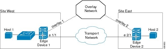
An edge device performs typical Layer 2 learning and forwarding on the site-facing interfaces (internal interfaces) and performs IP-based virtualization on the transport-facing interfaces. The edge device capability can be collocated in a device that performs Layer 2 and Layer 3 functionality. OTV functionality only occurs in an edge device. A given edge device can have multiple overlay interfaces. You can also configure multiple edge devices in a site.
OTV provides loop-free multihoming by electing a designated forwarding device per site for each VLAN. This forwarder is known as an Authoritative Edge Device (AED). The edge devices at the site communicate with each other on the internal interfaces to elect the AED.
The network that connects OTV sites. This network can be customer managed, provided by a service provider, or a mix of both.
One of the uplink interfaces of the edge device. The join interface is a point-to-point routed interface. The edge device joins an overlay network through this interface. The IP address of this interface is used to advertise reachability of a MAC address present in this site.
The Layer 2 interface on the edge device that connects to the VLANs that are to be extended. These VLANs typically form a Layer 2 domain known as a site and can contain site-based switches or site-based routers. The internal interface is a Layer 2 access or trunk interface regardless of whether the internal interface connects to a switch or a router.
Associates the destination MAC address of the Layer 2 traffic with an edge device IP address. The MAC to IP association is advertised to the edge devices through the OTV control-plane protocol. In MAC routing, MAC addresses are reachable through the IP address of a remote edge device on the overlay network. Layer 2 traffic destined to a MAC address is encapsulated in an IP packet based on the MAC to IP mapping in the MAC table.
A logical multi-access multicast-capable interface. The overlay interface encapsulates Layer 2 frames in IP unicast or multicast headers.
A logical network that interconnects remote sites for MAC routing of Layer 2 traffic. The overlay network is comprised of multiple edge devices.
A Layer 2 network that may be single-homed or multihomed to the transport network and the OTV overlay network. Layer 2 connectivity between sites is provided by edge devices that operate in an overlay network. Layer 2 sites are physically separated from each other by the transport network.
OTV sends local hello messages on the site VLAN to detect other OTV edge devices in the site and uses the site-VLAN to determine the authoritative edge device for the OTV-extended VLANs.
VLAN 1 is the default site VLAN. We recommend that you use a dedicated VLAN as a site VLAN. You should ensure that the site VLAN is active on at least one of the edge device ports and that the site VLAN is not extended across the overlay.
The overlay network provides Layer 2 connectivity between remote sites over a transport network. The overlay network consists of one or more edge devices on each site interconnected with a control-plane protocol across the transport network.
The overlay network maps MAC addresses to IP addresses of the edge devices. Once OTV identifies the correct edge device to send a Layer 2 frame to, OTV encapsulates the frame and sends the resulting IP packet using the transport network routing protocols.
OTV supports one or more separate overlay networks running IPv4 or IPv6 unicast forwarding or multicast flooding. Each overlay network supports one or more VLANs.
 Note |
OTV does not extend STP across sites. Each site runs its own STP rather than include all sites in a large STP domain. This topology also allows the use of different STP modes such as Per-VLAN Rapid Spanning Tree Plus (PVRST+) or Multiple Spanning Tree (MST) in each site. |
Each site consists of one or more edge devices and other internal routers, switches, or servers. OTV configuration occurs only on the edge device and is completely transparent to the rest of the site. This transparency applies to MAC learning, Spanning Tree Protocol (STP) root bridge placement, and STP mode. The edge device performs typical Layer 2 learning and forwarding on the internal interfaces and transmits and receives the encapsulated Layer 2 traffic on the physical interface through the transport network.
An edge device sends and receives control plane traffic through the join interface. The control plane traffic exchanges reachability information between remote sites to build up a table that maps MAC addresses to the IP address of the edge device that is local to the MAC address.
An edge device has internal interfaces that are part of the Layer 2 network in the site and has external interfaces that are reachable through IP in the transport network.
OTV builds Layer 2 reachability information by communicating between edge devices with the overlay protocol. The overlay protocol forms adjacencies with all edge devices. Once each edge device is adjacent with all its peers on the overlay, the edge devices share MAC address reachability information with other edge devices that participate in the same overlay network.
OTV discovers edge devices through dynamic neighbor discovery which leverages the multicast support of the core.
For transport networks that support IP multicast, one multicast address (the control-group address) is used to encapsulate and exchange OTV control-plane protocol updates. Each edge device that participates in the particular overlay network shares the same control-group address with all the other edge devices. As soon as the control-group address and the join interface are configured, the edge device sends an IGMP report message to join the control group. The edge devices act as hosts in the multicast network and send multicast IGMP report messages to the assigned multicast group address.
As in traditional link state routing protocols, edge devices exchange OTV control-plane hellos to build adjacencies with other edge devices in the overlay network. Once the adjacencies are established, OTV control-plane Link State Packets (LSPs) communicate MAC to IP mappings to the adjacent devices. These LSPs contain the IP address of the remote edge device, the VLAN IDs, and the learned MAC addresses that are reachable through that edge device.
Edge devices participate in data-plane learning on internal interfaces to build up the list of MAC addresses that are reachable within a site. OTV sends these locally learned MAC addresses in the OTV control-plane updates to remote sites.
When an edge device receives a Layer 2 frame on an internal interface, OTV performs the MAC table lookup based on the destination address of the Layer 2 frame. If the frame is destined to a MAC address that is reachable through another internal interface, the frame is forwarded out on that internal interface. OTV performs no other actions and the processing of the frame is complete.
If the frame is destined to a MAC address that was learned over an overlay interface, OTV performs the following tasks:
Strips off the preamble and frame check sequence (FCS) from the Layer 2 frame.
Adds an OTV header to the Layer 2 frame and copies the 802.1Q information into the OTV header.
Adds the IP address to the packet, based on the initial MAC address table lookup. This IP address is used as a destination address for the IP packet that is sent into the core switch.
OTV traffic appears as IP traffic to the network core.
At the destination site, the edge device performs the reverse operation and presents the original Layer 2 frame to the local site. That edge device determines the correct internal interface to forward the frame on, based on the local MAC address table.
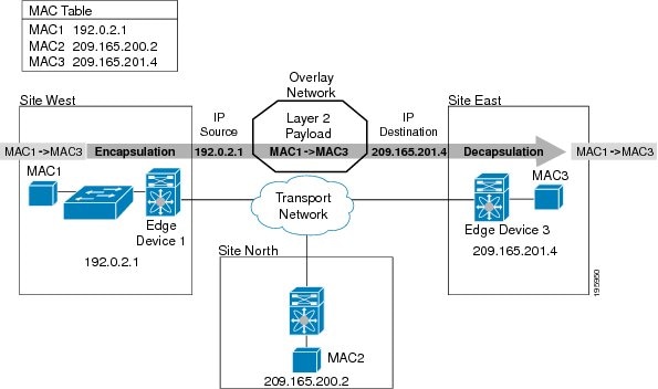
In this figure, Site West communicates with Site East over the overlay network. Edge Device 1 receives the Layer 2 frame from MAC1 and looks up the destination MAC address, MAC3, in the MAC table. The edge device encapsulates the Layer 2 frame in an IP packet with the IP destination address set for Edge Device 3 (209.165.201.4). When Edge Device 3 receives the IP packet, it strips off the IP header and sends the original Layer 2 frame onto the VLAN and port that MAC3 is connected to.
OTV uses a metric value to support seamless MAC mobility. The authoritative edge device that learns a new MAC address advertises that new address in the OTV control-plane updates with a metric value of one if no other edge device has advertised that MAC address before.
In the case of a mobile MAC address, the authoritative edge device advertises that newly learned local MAC address with a metric value of zero. This metric value signals the remote edge device to stop advertising that MAC address. Once the remote edge device stops advertising the moved MAC address, the authoritative edge device that contains the new MAC address changes the metric value to one.
Virtual Machine (VM) mobility is one common example of MAC mobility. VM mobility occurs when the virtual machine moves from one site to another. OTV detects this change based on the changed advertisement of the mobile MAC address.
You can use OTV to connect remote sites in multiple topologies.
In this sample topology, both sites are connected over a common transport network. The two edge devices both have an overlay interface configured (interface overlay 1 and interface overlay 2) with the same control-group address, which makes both edge devices join a common overlay network. While the control-group addresses of the two edge devices need to match, the figure shows that the external interface is unique for each edge device.
You can configure an edge device in more than one overlay network. Each overlay network uses a different multicast group address.
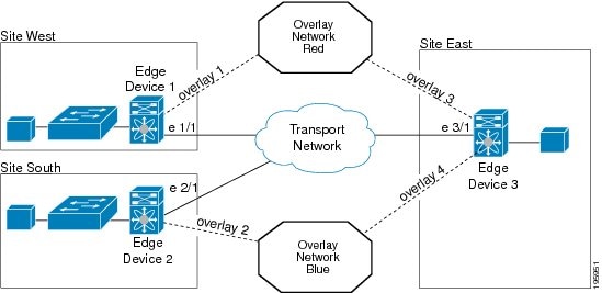
In this example, Site East connects to Site West over overlay network Red through overlay interface 3 on Edge Device 3 and connects to Site South over overlay network Blue through overlay interface 4 on Edge Device 3. Each overlay network has different control-group addresses.
Site East in this example uses Edge Device 3 to connect to both overlay networks. Edge Device 3 associates the same physical interface for both overlay networks.
For resiliency and load balancing, a site can have multiple edge devices.
When more than one edge device is present and both participate in the same overlay network, the site is considered multihomed. For the VLANs that are extended using OTV, one edge device is elected as the authoritative edge device on a per-VLAN basis. OTV leverages a local VLAN to establish an adjacency between edge devices on their internal interfaces. The local VLAN that is shared by the internal interfaces is the site VLAN. The adjacency establishment over the site VLAN determines the following information:
If the other edge device is still present
Which edge device is authoritative for what VLANs
Load balancing is achieved because each edge device is authoritative for a subset of all VLANs that are transported over the overlay. Link utilization to and from the transport is optimized.
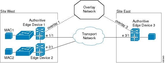
In this figure, Site West is a multihomed site, with two physical interfaces connected to the transport network.
An edge device can be authoritative for one set of VLANs but not authoritative for another set of VLANs.
Dual site adjacency includes adjacency discovery over the overlay network as well as on the existing site VLAN. This introduces additional resiliency and loop prevention caused by site VLAN partition or misconfiguration. Dual site adjacency also uses forwarding readiness notifications to detect when neighbor edge devices in the same site experience a change such as local failures such as the site VLAN or the extended VLANs going down or the join-interface going down. These forwarding readiness notifications trigger an immediate AED election for the site.
The dual site adjacency state is the result of the most recent adjacency state for either the overlay or site VLAN adjacency. OTV determines AED election based on active dual site adjacencies only. An inactive dual site adjacency is ignored for AED election.
You must configure the same site identifier for all edge devices in a site. OTV advertises this site identifier in the IS-IS hello packets sent over the overlay network and on the local site VLAN. The combination of the IS-IS system ID and site identifier uniquely identifies the edge devices on a site.
Note |
The Layer 3 core should not get arbitrarily partitioned resulting in edge devices having only partial reachability to other edge devices. An arbitrary core partition will result in traffic loss and should be fixed by ensuring that core is well-connected. |
OTV sends forwarding readiness notifications to all neighbors of an edge device in the event that the following isolation states occur:
All extended VLANs on an edge device go down.
All overlay adjacencies go down.
 Feedback