- Preface
- Overview
- Installing the Cisco VSG and the Cisco VNMC-Quick Start
- Installing the Cisco VSG
- Installing Cisco VNMC
- Registering Devices With the Cisco VNMC
- Installing the Cisco VSG on a Cisco Cloud Services Platform Virtual Services Appliance
- Upgrading the Cisco VSG and the Cisco VNMC
- Examples of Cisco VNMC OVA Template Deployment and Cisco VNMC ISO Installations
- Index
Installing Cisco VNMC
This chapter contains the following sections:
- Information About the Cisco VNMC
- Installation Requirements
- ESXi and ESX Server Requirement
- Installing Cisco VNMC
Information About the Cisco VNMC
The Cisco Virtual Network Management Center (Cisco VNMC) is a virtual appliance that provides centralized device and security policy management for Cisco virtual services. Designed to support enterprise and multiple-tenant cloud deployments, the Cisco VNMC provides transparent, seamless, and scalable management for securing virtualized data center and cloud environments.
Installation Requirements
Cisco VNMC System Requirements
Requirement |
Description |
|---|---|
Virtual Appliance |
|
One virtual CPU |
1.5 GHz |
Memory |
3-GB RAM |
Disk space |
25 GB on a shared network file storage (NFS) or a storage area network (SAN) if Cisco VNMC is deployed in a high availability (HA) cluster |
Management interface |
One management network interface |
Processor |
x86 Intel or AMD server with 64-bit processor listed in the VMware compatibility matrix |
VMware |
|
VMware vSphere |
Release 4.1 or 5.0 with VMware ESX or ESXi |
VMware vCenter |
Release 4.1 or 5.0 (English) |
Interfaces and Protocols |
|
HTTP/HTTPS |
— |
Lightweight Directory Access Protocol (LDAP) |
— |
Intel VT |
|
Intel Virtualization Technology (VT) |
Enabled in the BIOS |
Web-Based GUI Client Requirements
Requirement |
Description |
|---|---|
Operating system |
|
Browser |
|
Flash Player |
Adobe Flash Player plugin (version 11.2) |
Firewall Ports Requiring Access
Requirement |
Description |
|---|---|
80 |
HTTP/TCP |
443 |
HTTP |
843 |
TCP |
Cisco Nexus 1000V Series Switch Requirements
Requirement |
Notes |
|---|---|
General |
|
The procedures in this guide assume that the Cisco Nexus 1000V Series switch is up and running, and that endpoint Virtual Machines (VMs) are installed. |
— |
VLANs |
|
|
|
Neither VLAN needs to be the system VLAN. |
Port Profiles |
|
One port profile configured on the Cisco Nexus 1000V Series Switch for the service VLAN. |
— |
Information Required for Installation and Configuration
Information Type |
Your Information |
||
|---|---|---|---|
For Deploying the VNMC OVA |
|||
Name |
|||
Location of files |
|||
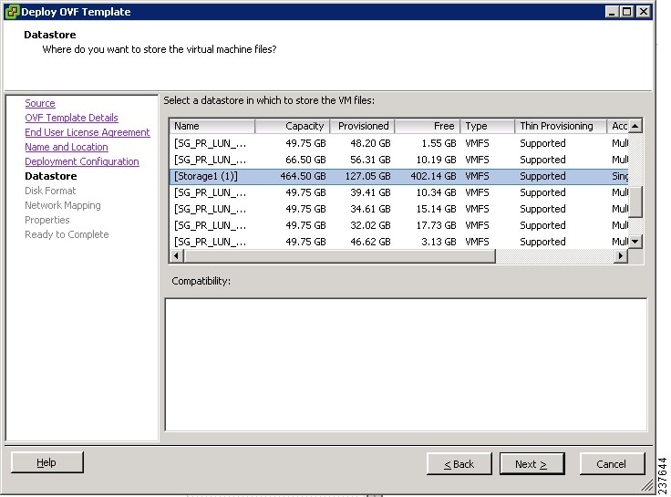
Datastore location |
|||
Storage location, if more than one location is available |
|||
|
|||
IP address |
|||
Subnet mask |
|||
Gateway IP address |
|||
Domain name |
|||
DNS server |
|||
Admin password |
|||
Shared secret password for communications between the Cisco VNMC, Cisco VSG, and VSM. |
|||
For Configuring vCenter in VNMC |
|||
vCenter name |
|||
Description |
|||
Hostname or IP address |
|||
Shared Secret Password Criteria
A shared secret password is a password that is known only to those using a secure communication. Passwords are designated strong if they cannot be easily guessed for unauthorized access. When you set a shared secret password for communications between the Cisco VNMC, Cisco VSG, and VSM, adhere to the following criteria for setting valid, strong passwords:
ESXi and ESX Server Requirement
You must set the clock to the correct time on all ESXi and ESX servers that will run Cisco VNMC, ASA 1000V instances, Cisco VSG, or VSM. If you do not set the correct time on the server, the Cisco VNMC CA certificate that is created when the Cisco VNMC VM is deployed might have an invalid time stamp. An invalid time stamp can prevent you from successfully registering ASA 1000V instances to the Cisco VNMC.
Installing Cisco VNMC
You can deploy the VNMC OVA, resulting in a VNMC VM.
- You must set your keyboard to United States English before installing the Cisco VNMC and using the VM console.
- Verify that the VNMC OVA image is available in the vSphere client.
- Make sure that all system requirements are met as recommended in Cisco VNMC System Requirements.
- Make sure you have the information identified as in Information Required for Installation and Configuration.


 Feedback