Installing the Cisco Prime NSC and Cisco VSG-Quick Start

This chapter contains the following sections:

Information About Installing Cisco Prime NSC and Cisco VSG

This chapter describes how to install and set up a basic working configuration of Cisco Prime Network Services Controller (Cisco PNSC) and Cisco Virtual Security Gateway (Cisco VSG). The example in this chapter uses the ISO files of the software for installation. The steps assume that Cisco Nexus 1000V Series switch is operational, and endpoint VMs are already installed.

Cisco VSG and Cisco Prime NSC Installation Planning Checklists

Planning the arrangement and architecture of your network and equipment is essential for a successful operation of Cisco PNSC and Cisco VSG.

Basic Hardware and Software Requirements

The following table lists the basic hardware and software requirements for Cisco VSG and Cisco PNSC installation.

Requirement Description

Virtual CPUs

  • Cisco VSG: 1 (1.5 GHz)

  • Cisco PNSC: 4 (1.8 GHz each)

Memory

  • Cisco VSG: 2GB RAM

  • Cisco PNSC: 4GB RAM

Disk Space

Cisco VSG: 3 GB

Cisco Prime NSC: Without InterCloud functionality, 40 GB on shared NFS or SAN, and configured on two disks as follows:

  • Disk 1: 20 GB

  • Disk 2: 20 GB

Processor

x86 Intel or AMD server with a 64-bit processor.

Network Interfaces

  • Cisco VSG: 3

  • Cisco PNSC: 1

Microsoft SCVMM

SCVMM 2012 SP1, SCVMM 2012 R2, or SCVMM 2016

Browser

Any of the following browsers:

  • Internet Explorer 9.0 or higher

  • Mozilla Firefox 23.0 or higher

  • Google Chrome 29.0 or higher

Note 
If you are running Firefox or IE and do not have Flash, or you have a version of Flash that is older than 11.2, a message displays asking you to install Flash and provides a link to the Adobe website.
Note 
Before using Google Chrome with Cisco PNSC, you must disable the Adobe Flash Players that are installed by default with Chrome.

Ports

Access to the Cisco PNSC application using a web browser and the following ports (if the deployment uses a firewall, make sure to permit the following ports):

  • 443 (HTTPS)

  • 80 (HTTP/TCP)

  • 843 (Adobe Flash)

Flash Player

Adobe Flash Player plugin 11.2 or higher


Note

The Cisco VSG software is available for download at http://www.cisco.com/en/US/products/ps13095/index.html and the Cisco PNSC software is available for download at http://www.cisco.com/en/US/products/ps13213/index.html.


License Requirements

Cisco VSG license is integrated with the Nexus1000V Multi-Hypervisor License. You need to install the Nexus1000V Multi-Hypervisor License for Cisco VSG for Microsoft Hyper-V. The Cisco N1kv VSM is available in two modes: essential and advanced. VSG functionality is available only in the advanced mode. You need to install the Nexus1000V Multi-Hypervisor License and change the VSM mode to advanced mode. When the Nexus1000V Multi-Hypervisor License is installed, the license for Cisco VSG is automatically included.

Note

If you try to access VSG services with VSM in essential mode, an error message is generated on VSM console indicating that the Nexus1000V Multi-Hypervisor License is required for VSG.
Starting with Release 5.2(1)SM1(5.2), Cisco Nexus1000V Multi-Hypervisor License is available in three different types:
  • Default: The Nexus 1000v switch may be configured in Essential or Advanced mode.
    • Essential Mode: Not Supported.
    • Advanced Mode: After upgrade to Software Release 5.2(1)SM(5.2) or later- Nexus1000V Multi-Hypervisor License is available with 1024 Socket Count and expires in 60 days.

    Note

    You must install either the evaluation or the permanent (MSFT PKG) license prior to upgrading to the Software Release 5.2(1)SM1(5.2) or later.
  • Evaluation: The Nexus 1000V switch should be in Advanced mode. After upgrading to Software Release 5.2(1)SM1(5.2) or later - Nexus1000V Multi-Hypervisor License is available with1024 Socket Count and expires in 60 days.
  • Permanent: The Nexus 1000V switch should be in Advanced mode. After upgrading to Software Release 5.2(1)SM1(5.2) or later - Nexus1000V Multi-Hypervisor License is available with 1024 Socket Count and expires in 60 days.

Note

You have to request for an evaluation or permanent Nexus1000V Multi-Hypervisor License.

For more information about the Cisco Nexus 1000V for Microsoft Hyper-V licenses, see the Cisco Nexus 1000V for Microsoft Hyper-V License Configuration Guide.

VLAN Configuration Requirements for VSG

You must have two port-profiles configured on two different VLANs in the VSM:
  • Service interface VLAN
  • HA interface VLAN

Required Cisco Prime NSC and Cisco VSG Information

The following information can be used during the Cisco PNSC and Cisco VSG installation.

Type Your Information

Cisco VSG name—Unique within the inventory folder and up to 80 characters

Hostname—Where the Cisco VSG will be installed in the inventory folder

ISOs—Managed within SCVMM library, if stored at C:\ProgramData\Virtual Machine Manager Library Files\ISO to manage. Refresh the SCVMM library after saving the ISO file to the specified location.

Cisco VSG management IP address

VSM management IP address

Cisco PNSC instance IP address

Mode for installing the Cisco VSG

  • Standalone

  • HA primary

  • HA secondary

Cisco VSG VLAN number

  • Service (1)

  • Management (2)

  • High availability (HA) (3)

Cisco VSG port profile name

  • Data (1)

  • Management (2)

  • High availability (HA) (3)

Note 

The numbers indicate the Cisco VSG port profile that must be associated with the Cisco VSG VLAN number.

HA pair ID (HA domain ID)

Cisco VSG admin password

Cisco PNSC admin password

Cisco VSM admin password

Shared secret password (Cisco PNSC, Cisco VSG policy agent, Cisco VSM policy agent)

NSC DNS IP address
NSC NTP IP address

Host Requirements

  • Microsoft SCVMM 2012 R2 or Microsoft SCVMM 2016

  • Windows Server 2012 R2 or Windows Server 2016

  • 6 GB RAM

Task 1: Installing the Cisco Prime NSC from an ISO Image

Before you begin

Ensure that you have:

  • Verified that the Hyper-V host on which to deploy Cisco PNSC VM is available in SCVMM.

  • Copied the Cisco PNSC 3.4 ISO image to the SCVMM library location on the file system. To make this image available in SCVMM, choose Library > Library Servers, right-click the library location, and then refresh.

  • NTP server information.

SUMMARY STEPS

  1. Launch the SCVMM.
  2. In the VMs and Services pane, choose the Hyper-V host on which to deploy the Cisco PNSC VM.
  3. Right-click the Hyper-V host and choose Create Virtual Machine.
  4. In the Create Virtual Machine wizard, from the Select Source screen, choose the Create the new virtual machine with a blank virtual hard disk radio button, and then click Next.
  5. In the Specify Virtual Machine Identity screen, Specify the name and description for the virtual machine, and then click Next.
  6. In the Configure Hardware screen, do the following:
  7. In the Select Destination screen, do the following:
  8. In the Select Host screen, choose the destination, and then click Next.
  9. In the Configure Settings screen, click Browse and navigate to the storage location of virtual machine file, and then click Next.
  10. In the Add properties screen, choose the Red Hat Enterprise Linux 5 (64 bit) operating system, and then click Next.
  11. In the Summary screen, do the following:
  12. After the VM is successfully created, right-click the new Virtual Machine and choose Connect or View > Connect Via Console.
  13. Launch the console and install Cisco PNSC.
  14. After Cisco PNSC is successfully deployed, click Close and power on the Cisco PNSC VM.

DETAILED STEPS


Step 1

Launch the SCVMM.

Figure 1. Create Virtual Machine Wizard - Select Source
Step 2

In the VMs and Services pane, choose the Hyper-V host on which to deploy the Cisco PNSC VM.

Step 3

Right-click the Hyper-V host and choose Create Virtual Machine.

Step 4

In the Create Virtual Machine wizard, from the Select Source screen, choose the Create the new virtual machine with a blank virtual hard disk radio button, and then click Next.

Step 5

In the Specify Virtual Machine Identity screen, Specify the name and description for the virtual machine, and then click Next.

Step 6

In the Configure Hardware screen, do the following:

  1. From General, do the following:

    • Choose Processor and set the number of processors.

    • Choose Memory and choose the required memory value. You will need a minimum 4 GB of memory.

  2. From Bus Configuration > IDE Devices, do the following:

    • Choose the hard disk with the virtual machine name you specified and enter the required size of the hard disk. You will need at least 20 GB.

    • Click New > Disk to add a new hard disk, enter hard disk name in the File Name field, set the hard disk size to 20 GB and click Ok.
    • Choose Virtual DVD Drive, choose the Existing ISO image file radio button, and browse to select the Cisco PNSC 3.4 ISO image file from the library in the Select ISO dialog box.

  3. Choose Network Adapters > Network Adapter 1, select the Connect to a VM Network radio button, and browse to select a VM Network.

  4. Click Next.

Step 7

In the Select Destination screen, do the following:

  1. Choose the Place the virtual machine on a host radio button.

  2. From the Destination drop-down list, choose All hosts.

  3. Click Next.

Step 8

In the Select Host screen, choose the destination, and then click Next.

Step 9

In the Configure Settings screen, click Browse and navigate to the storage location of virtual machine file, and then click Next.

Step 10

In the Add properties screen, choose the Red Hat Enterprise Linux 5 (64 bit) operating system, and then click Next.

Step 11

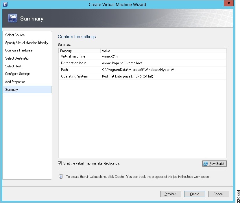
In the Summary screen, do the following:

  1. Verify the settings.

  2. Check the Start the virtual machine after deploying it check box.

  3. Click Create.

    Figure 2. Create Virtual Machine Wizard - Summary

    The job Create VM starts. You can see the status of this job in the Recent Jobs window. Ensure that the job completes without any errors.

Step 12

After the VM is successfully created, right-click the new Virtual Machine and choose Connect or View > Connect Via Console.

Step 13

Launch the console and install Cisco PNSC.

Note 

Before the final Cisco PNSC installation step, before you reboot, launch SCVMM again, and right-click the Virtual machine and choose Properties > Hardware Configuration > Bus Configuration > Virtual DVD Drive > no media, so that Cisco PNSC does not use the ISO image at boot time.

Step 14

After Cisco PNSC is successfully deployed, click Close and power on the Cisco PNSC VM.


Task 2: On the VSM, Configuring Cisco Prime NSC Policy Agent

Once Cisco PNSC is installed, you must register the VSM with Cisco PNSC.

Before you begin

Ensure that you have:

  • Cisco PNSC policy-agent image on the VSM (for example, vsmhv-pa.3.2.1e.bin)


    Note

    The string vsmhv-pa must appear in the image name as highlighted.


  • The IP address of Cisco PNSC

  • The shared secret password you defined during Cisco PNSC installation

  • IP connectivity between the VSM and Cisco PNSC is working


    Note

    If you upgrade your VSM, you must also copy the latest Cisco VSM policy agent image. This image is available in Cisco PNSC image bundle to boot from a flash drive and to complete registration with Cisco PNSC.


Note

VSM clock should be synchronized with Cisco PNSC clock.


SUMMARY STEPS

  1. On the VSM, enter the following commands:
  2. Check the status of the NSC policy agent configuration to verify that you have installed Cisco PNSC correctly and it is reachable by entering the show nsc-pa status command. This example shows that Cisco PNSC is reachable and the installation is correct:

DETAILED STEPS


Step 1

On the VSM, enter the following commands:

vsm# configure terminal
vsm(config)# nsc-policy-agent
vsm(config-nsc-policy-agent)# registration-ip 10.193.75.95
vsm(config-nsc-policy-agent)# shared-secret Example_Secret123
vsm(config-nsc-policy-agent)# policy-agent-image vsmhv-pa.3.2.1e.bin
vsm(config-nsc-policy-agent)# exit
vsm(config)# copy running-config startup-config
vsm(config)# exit
Step 2

Check the status of the NSC policy agent configuration to verify that you have installed Cisco PNSC correctly and it is reachable by entering the show nsc-pa status command. This example shows that Cisco PNSC is reachable and the installation is correct:

vsm# show nsc-pa status
NSC Policy-Agent status is - Installed Successfully. Version 3.2(1e)-vsm
vsm

The VSM is now registered with Cisco PNSC.


Example

This example shows that Cisco PNSC is unreachable or an incorrect IP is configured:

vsm# show nsc-pa status
nsc Policy-Agent status is - Installation Failure
Cisco PNSC not reachable.
vsm# 

This example shows that the NSC policy-agent is not configured or installed:

vsm# show nsc-pa status
NSC Policy-Agent status is - Not Installed

Task 3: On the VSM, Preparing Cisco VSG Port Profiles

To prepare Cisco VSG port profiles, you must create the VLANs and use the VLANs in Cisco VSG data port profile and the Cisco VSG-ha port profile.

Before you begin

Ensure that you have:

  • Logical Switch name (Network Uplink port-profile name).

  • VLAN ID for the Cisco VSG data interface (for example,100).

  • VLAN ID for the Cisco VSG-ha interface (for example, 200).

  • Management VLAN (management).


    Note

    None of these VLANs need to be system VLANs.


SUMMARY STEPS

  1. Create a Cisco VSG data port profile and a Cisco VSG-ha port profile by first enabling the Cisco VSG data port-profile configuration mode. Cisco VSG data interface should be in the system VLAN. To configure VSG data interface in the system VLAN, you need a system network segment, a system port-profile, and an uplink configured as a system uplink. Use the configure command to enter global configuration mode.
  2. Create Network Uplink port-profile and use it in the Logical Switch.
  3. Create the network segment and port-profile for the Data VLAN.
  4. Create the network segment and port-profile for the HA VLAN.

DETAILED STEPS


Step 1

Create a Cisco VSG data port profile and a Cisco VSG-ha port profile by first enabling the Cisco VSG data port-profile configuration mode. Cisco VSG data interface should be in the system VLAN. To configure VSG data interface in the system VLAN, you need a system network segment, a system port-profile, and an uplink configured as a system uplink. Use the configure command to enter global configuration mode.

Important 
Ensure that all the critical VMs are configured in the system VLANs.
vsm# configure
Step 2

Create Network Uplink port-profile and use it in the Logical Switch.

vsm(config)# nsm  logical network vsm_LogicalNet
vsm(config-logical-net)# exit 

vsm(config)# nsm network segment pool vsm_NetworkSite
vsm(config-net-seg-pool)# member-of logical network vsm_LogicalNet
vsm(config-net-seg-pool)# exit

vsm(config)# nsm ip pool template pool-vmk-n
vsm(config-ip-pool-template)# address family ipv4
vsm(config-ip-pool-template)# network 90.90.90.0/24
vsm(config-ip-pool-template)# ip address 90.90.90.2 90.90.90.100
vsm(config-ip-pool-template)# default-router 90.90.90.1
vsm(config-ip-pool-template)# exit

vsm(config)#port-profile type ethernet sys-uplink
vsm(config-port-prof)#channel-group auto
vsm(config-port-prof)#no shutdown
vsm(config-port-prof)#system port-profile
vsm(config-port-prof)#state enabled
vsm(config-port-prof)#exit

vsm(config)# nsm network uplink vsm_Uplink
vsm(config-uplink-net)# allow network segment pool vsm_NetworkSite
vsm(config-uplink-net)# import port-profile sys_Uplink
vsm(config-uplink-net)# system network uplink
vsm(config-uplink-net)# publish uplink-network
vsm(config-uplink-net)# exit

Step 3

Create the network segment and port-profile for the Data VLAN.

vsm(config)# nsm network segment VMAccess_502
vsm(config-net-seg)# member-of network segment pool vsm_NetworkSite
vsm(config-net-seg)# system network segment
vsm(config-net-seg)# switchport access vlan 502
vsm(config-net-seg)# ip pool import template VM_IP_Pool
vsm(config-net-seg)# publish network-segment
vsm(config-net-seg)# exit
vsm(config)# port-profile type vethernet VSG_Data
vsm(config-port-prof)# no shutdown
vsm(config-port-prof)# state enabled
vsm(config-port-prof)# system port-profile
vsm(config-port-prof)# publish port-profile
vsm(config-port-prof)# exit
Step 4

Create the network segment and port-profile for the HA VLAN.

vsm(config)# nsm network segment VMAccess_503
vsm(config-net-seg)# member-of network segment pool vsm_NetworkSite
vsm(config-net-seg)# switchport access vlan 503
vsm(config-net-seg)# ip pool import template VM_IP_Pool
vsm(config-net-seg)# publish network-segment
vsm(config-net-seg)# exit
vsm(config)# port-profile type vethernet VSG_HA
vsm(config-port-prof)# no shutdown
vsm(config-port-prof)# state enabled
vsm(config-port-prof)# publish port-profile
vsm(config-port-prof)# exit

Task 4: On the VSM, Configuring Virtual Network Adapters on the Hosts

Now that you have prepared Cisco VSG port profiles on VSM, you should configure virtual network adapters on the hosts.

This task includes the following subtasks:

Before you begin

Ensure that you have:

  • Cisco VSG port-profile configured on VSM.

Create Port-profile for the Virtual Network Adapter

You need to log in to VSM to create port-profile for the virtual network adapter.

SUMMARY STEPS

  1. Create port-profile for the virtual network adapter in VSM.

DETAILED STEPS


Create port-profile for the virtual network adapter in VSM.

Example:

vsm#configure terminal
vsm(config)#port-profile type vethernet Virtual-Net-PP
vsm(config-port-prof)#capability l3-vservice
vsm(config-port-prof)#no shutdown
vsm(config-port-prof)#state enabled
vsm(config-port-prof)#publish port-profile
vsm(config-port-prof)#exit
vsm#copy running-config startup-config

Creating Virtual Network Adapter

Before you begin

Make sure that you know the following:

  • Port-profile for virtual network adapter is created.

Procedure


Step 1

Launch SCVMM.

Step 2

In the VMs and Services tab, click All Hosts.

Step 3

Choose the host on which you want to add the virtual network adapter.

Step 4

Right-click the host and choose Properties from the pop-up menu.

Step 5

In the Properties window, click Virtual Switches.

Step 6

On the Virtual Switches tab, click New Virtual Network Adapter.

Step 7

In the Name field, enter name of virtual network adapter.

Step 8

Under the Connectivity, in the VM Network field, choose an appropriate VM network.

Step 9

Under Port profile, select L3 service enabled port-profile that you created from the Classification drop-down list.

Step 10

Under IP address configuration, check Static radio-button and do the following:

  1. Choose IP-pool for virtual network adapter from the IPv4 pool drop-down list.

  2. In the IPv4 address field, enter IP address for virtual network adapter.

Step 11

Click Ok.

Step 12

The VM manager warning message appears, click Ok.


What to do next

Add a physical router between VSG and virtual network adapter.

Task 5: Installing Cisco VSG from an ISO Image


Note

Cisco VSG is supported as VSB on Nexus Cloud Services platform only.


Before you begin

Ensure that you have:

  • Installed Microsoft SCVMM 2012 R2 or Microsoft SCVMM 2016.

  • Downloaded the Cisco VSG ISO image and uploaded it to the server (C:\ProgramData\Virtual Machine Manager Library Files\ISO). Refresh the library server under the Library tab.

  • Cisco VSG-Data port profile: VSG-Data.

  • Cisco VSG-ha port profile: VSG-ha.

  • HA ID.

  • IP/subnet mask/gateway information for Cisco VSG

  • Administrator password

  • Minimum of 2 GB RAM and 3 GB hard disk space, recommended space is 4 GB RAM and 4 GB hard disk.

  • Cisco PNSC IP address.

  • The shared secret password.

  • IP connectivity between Cisco VSG and Cisco PNSC is okay.

  • Cisco VSG NSC-PA image name (vnmc-vsgpa.2.1.2a.bin) is available.

Procedure


Step 1

Launch SCVMM.

Step 2

On the VMs and Services tab, click Create Virtual Machine.

Step 3

In the Create Virtual Machine Wizard, in the Select Source screen, check the Create the new virtual machine with a blank virtual hard disk radio button, and click Next.

Step 4

In the Specify Virtual Machine Identity screen, enter the name for the Cisco VSG in the Virtual machine name field and click Next.

Figure 3. Create Virtual Machine Wizard - Specify Virtual Machine Identity
Step 5

In the Configure Hardware section, do the following:

  1. Under General, choose Memory, choose the Static option, and enter 2048 MB in the Virtual machine memory field.

  2. Under Bus Configuration, choose the primary disk and enter 2 in the Size (GB) field.

  3. Choose the virtual DVD Drive, select the Existing ISO image file radio button and browse for the VSG ISO within the SCVMM Library.

  4. Click New > Network Adapter to create a total of three new Network Adapters.

    • Under the Network Adapters section, choose Network Adapter 1, and then choose Connected to a VM network and browse for the appropriate network that corresponds to the network segment for the VSG's data interface.
      Note 

      Network Adapter 1 is Service/Data network, use it to connect to the Data network.

      Note 

      Network Adapter 2 is the management network, connect it to the management network for the VSG.

      Note 

      Network Adapter 3 is the HA network, connect it to the HA network.

      Figure 4. Create Virtual Machine Wizard - Configure Hardware
    • From the Classification drop-down list, choose the port-profile corresponding to the VSG's data interface.

    Note 

    Repeat Step d to create network adapters for management and HA.

Step 6

In the Select Destination section, choose Place the virtual machine in a host, choose the host group on which you want to store the VSG from the drop-down list, and click Next.

Step 7

In the Select Host section, choose the host that you want to place the VSG on and click Next.

Step 8

In the Configure Settings section, review the virtual machine settings to ensure they are correct, and click Next.

Step 9

(Optional) In the Add Properties section, choose the Other Linux (64-bit) from the Operating System from the drop-down list, and then click Next.

Step 10

In the Summary section, click Create.

Step 11

Once the VSG is successfully installed, choose the VSG on the VMs and Services tab, and click Power On.

Step 12

Connect to the VSG using Connect or View > Connect via Console.


Task 6: On the VSG, Configuring the Cisco Prime NSC Policy Agent

Once Cisco PNSC is installed, you must register Cisco VSG with Cisco PNSC.

Before you begin

Ensure that you have:

  • The Cisco PNSC policy-agent image on Cisco VSG (for example, vnmc-vsgpa.2.1.2a.bin).


    Note

    The string vsgpa must appear in the image name as highlighted.


  • IP address of the Cisco PNSC.

  • Shared secret password you defined during the Cisco PNSC installation.

  • IP connectivity between the VSG and the Cisco PNSC.


    Note

    If you upgrade your VSG, you must also copy the latest Cisco VSG policy agent image. This image is available in Cisco PNSC image bundle to boot from a flash drive and to complete registration with Cisco PNSC.


Note

VSG clock should be synchronized with Cisco PNSC clock.


SUMMARY STEPS

  1. On Cisco VSG, configure the NSC policy agent:
  2. Check the status of the NSC policy agent configuration to verify that you have installed Cisco PNSC correctly and it is reachable by entering the show nsc-pa status command. This example shows that Cisco PNSC is reachable and the installation is correct:

DETAILED STEPS


Step 1

On Cisco VSG, configure the NSC policy agent:

VSG-Firewall# configure
Enter configuration commands, one per line.  End with CNTL/Z.
VSG-Firewall(config)# nsc-policy-agent
VSG-Firewall(config-nsc-policy-agent)# registration-ip 10.193.72.242
VSG-Firewall(config-nsc-policy-agent)# shared-secret Sgate123
VSG-Firewall(config-nsc-policy-agent)# policy-agent-image vnmc-vsgpa.2.1.2a.bin
VSG-Firewall(config-nsc-policy-agent)# copy running-config startup-config
[########################################] 100%
Copy complete, now saving to disk (please wait)...
VSG-Firewall(config-nsc-policy-agent)# exit
Step 2

Check the status of the NSC policy agent configuration to verify that you have installed Cisco PNSC correctly and it is reachable by entering the show nsc-pa status command. This example shows that Cisco PNSC is reachable and the installation is correct:

VSG-Firewall(config)# show nsc-pa status
NSC Policy-Agent status is - Installed Successfully. Version 2.1(2a)-vsg
Cisco VSG is now registered with Cisco PNSC.

Example

This example shows that Cisco PNSC is unreachable or an incorrect IP is configured:

vsg# show nsc-pa status
NSC Policy-Agent status is - Installation Failure
Cisco PNSC not reachable.
vsg# 

This example shows that the NSC policy-agent is not configured or installed:

vsg# show nsc-pa status
NSC Policy-Agent status is - Not Installed

Task 7: On Cisco VSG, Cisco VSM, and Cisco PNSC, Verifying the NSC Policy-Agent Status

You can use the show nsc-pa status command to verify the nsc policy-agent status on Cisco VSG, Cisco VSM, and Cisco Prime NSC (which can indicate that you have installed the policy-agent successfully).

SUMMARY STEPS

  1. Log in to the Cisco VSG.
  2. Check the status of NSC-PA configuration by entering the following command:
  3. Log in to the Cisco VSM.
  4. Check the status of NSC-PA configuration by entering the following command:
  5. Log in to Cisco PNSC.
  6. Click Resource Management and then click Resources.
  7. In the navigation pane, click VSMs and verify the VSM information in the VSMs pane.
  8. In the navigation pane, click VSGs and verify the VSG information in the VSGs pane.

DETAILED STEPS


Step 1

Log in to the Cisco VSG.

Step 2

Check the status of NSC-PA configuration by entering the following command:

vsg# show nsc-pa status
NSC Policy-Agent status is - Installed Successfully. Version 2.1(2a)-vsg
vsg#
Step 3

Log in to the Cisco VSM.

Step 4

Check the status of NSC-PA configuration by entering the following command:

VSM# show nsc-pa status
NSC Policy-Agent status is - Installed Successfully. Version 3.2(1e)-vsm
VSM#
Step 5

Log in to Cisco PNSC.

Step 6

Click Resource Management and then click Resources.

Step 7

In the navigation pane, click VSMs and verify the VSM information in the VSMs pane.

Step 8

In the navigation pane, click VSGs and verify the VSG information in the VSGs pane.


Task 8: On Cisco PNSC, Configuring a Tenant, Security Profile, Compute Firewall, and Assigning Cisco VSG to the Compute Firewall

Now that you have Cisco PNSC and Cisco VSG successfully installed with the basic configurations, you should configure the basic security profiles and policies.

This task includes the following subtasks:

What to do next

Go to Configuring a Tenant on Cisco Prime NSC

Configuring a Tenant on Cisco Prime NSC

Tenants are entities (businesses, agencies, institutions, and so on) whose data and processes are hosted on VMs on the virtual data center. To provide firewall security for each tenant, the tenant must first be configured in Cisco PNSC.

SUMMARY STEPS

  1. From the Cisco PNSC toolbar, click the Tenant Management tab.
  2. In the Navigation pane directory tree, right-click root, and from the drop-down list, choose Create Tenant.
  3. In the Create Tenant dialog box, do the following:
  4. Click OK.

DETAILED STEPS


Step 1

From the Cisco PNSC toolbar, click the Tenant Management tab.

Step 2

In the Navigation pane directory tree, right-click root, and from the drop-down list, choose Create Tenant.

Step 3

In the Create Tenant dialog box, do the following:

  1. In the Name field, enter the tenant name; for example, Tenant-A.

  2. In the Description field, enter a description for that tenant.

Step 4

Click OK.

Notice that the tenant that you have just created is listed in the left-side pane under root.


What to do next

See Configuring a Security Profile on the Cisco Prime NSC

Configuring a Security Profile on the Cisco Prime NSC

You can configure a security profile on Cisco PNSC.

Procedure


Step 1

In the Cisco PNSC toolbar, click the Policy Management>Service Profiles.

Step 2

In the Root navigation window, from the directory path, choose Tenant > Compute Firewall > Compute Security Profile.

Step 3

Right-click Compute Security Profile and choose Add Compute Security Profile.

The Add Compute Security Profile dialog box opens.

Step 4

In the Add Compute Security Profile dialog box, do the following:

  1. In the Name field, enter a name for the security profile; for example, sp-web.

  2. In the Description field, enter a brief description of this security profile.

Step 5

Click OK


What to do next

See Configuring a Compute Firewall and Assigning Cisco VSG to Cisco Prime NSC

Configuring a Compute Firewall and Assigning Cisco VSG to Cisco Prime NSC

The compute firewall is a logical virtual entity that contains the device profile that you can bind (assign) to Cisco VSG VM. The device policy in the device profile is then pushed from Cisco PNSC to Cisco VSG. Once this is complete, the compute firewall is in the applied configuration state on Cisco PNSC.

Procedure


Step 1

From Cisco PNSC, choose Resource Management > Managed Resources.

Step 2

On the left-pane directory tree, navigate to choose a tenant.

Step 3

Click the Action drop-down list, choose Add Compute Firewall. The Add Compute Firewall dialog box opens.

Step 4

In the Add Compute Firewall dialog box, do the following:

  1. In the Name field, enter a name for the compute firewall.

  2. In the Description field, enter a brief description of the compute firewall.

  3. In the Host Name field, enter the name for your Cisco VSG.

Step 5

Click Next.

The new Compute Firewall pane displays with the information that you provided.

Step 6

In the Select Service Devices pane, choose Assign VSG radio button, from the VSG Devices drop-down, choose a VSG. then and click Next.

Step 7

In the Interface tab, Configure Data Interface pane, enter data interface (data0) IP address and subnet mask, and click Next.

Step 8

Verify the configuration in Summary tab and click Finish.

Step 9

Click Root > Tenant > Network Services and verify the status of the firewall.


Task 9: On the Prime NSC, Configuring a Permit-All Rule

You can configure a permit-all rule in the Cisco PNSC.

Procedure


Step 1

Log in to the Cisco PNSC.

Step 2

Choose Policy Management > Service Profiles.

Step 3

Choose Root > Tenant > Compute Firewall > Compute Security Profile, and then select a security profile.

Step 4

In the right pane, click Add ACL Policy Set.

Step 5

In the Add ACL Policy dialog box, do the following:

  1. In the Name field, enter the ACL Policy Set name.

  2. In the Description field, enter a brief description of the ACL Policy Set.

  3. Click Add ACL Policy.

Step 6

In the Add ACL Policy dialog-box, enter the policy name, enter policy description, and then click Add Rule.

Step 7

In the Add Rule dialog box, do the following:

  1. In the Name field, enter the rule name.

  2. For the Action radio button, choose the matching condition (for example, Permit-All to permit all the traffic).

  3. On the Condition Match Criteria field, choose the required condition.

  4. On the Source - Destination - Service tab, click Add to add source/destination conditions or service.

  5. On the Protocol tab, uncheck Any to choose specific protocols. Do not uncheck Any if you wish to match all the protocols.

  6. On the Ether-Type tab, click Add to specify an Ether type for the rule.

  7. On the Time Range tab, keep the default option to leave the rule enabled.

  8. On the Advanced tab, click Add to add checks for source ports.

  9. Click Ok.

Step 8

In the Add Policy dialog box, click OK.

The newly created policy is displayed in the Assigned field.

Step 9

In the Add Policy Set dialog box, click OK.

Step 10

In the Service Profile window, click Save.


Task 10: On Cisco VSG, Verifying the Permit-All Rule

You can verify the rule presence in Cisco VSG, by using the Cisco VSG CLI and the show commands.

vsg# show running-config rule
rule POL-DEMO/R-DEMO@root/Tenant/VDC 
cond-match-criteria: match-allaction permit
rule POL1/R1@root/Tenant/VDC 
cond-match-criteria: match-allaction permit
rule default/default-rule@root 
cond-match-criteria: match-allaction drop
vsg#

Task 11: Enabling Logging

To enable logging follow these procedures:

Enabling Logging level 6 for Policy-Engine Logging

Logging enables you to see what traffic is going through your monitored virtual machine. This logging is helpful for verifying that you have a proper configuration and to help in troubleshooting. You can enable Logging Level 6 for policy-engine logging in a monitor session.

Procedure


Step 1

Log in to Cisco PNSC.

Step 2

Choose Policy Management > Device Configurations.

Step 3

In the Navigation pane, choose root > Policies > Syslog > Default, and then click Edit.

Step 4

In the Edit Syslog dialog box, do the following:

  1. Click the Servers tab.

  2. In the Server Type column, choose the primary server type from the displayed list.

  3. From the pane toolbar, click Edit.

Figure 5. Edit Syslog Dialog Box
Step 5

In the Edit Syslog Client dialog box, do the following:

  1. In the Hostname/IP address field, enter the syslog server IP address.

  2. From the Severity drop-down list, choose Information(6).

  3. From the Admin State drop-down list, check Enabled radio button.

  4. Click OK.

Step 6

Click OK.


What to do next

See Enabling Global Policy-Engine Logging.

Enabling Global Policy-Engine Logging

Logging enables you to see what traffic is going through your monitored VM. This logging is helpful for verifying that you have a proper configuration and to help in troubleshooting.

Procedure


Step 1

Log in to Cisco PNSC.

Step 2

In the Cisco Prime NSC window, choose Policy Management > Device Configurations > root > Device Profiles > default. The default Device Profile window opens.

Step 3

In the default pane, do the following:

  1. In the Work pane, click the General tab.

  2. In the Policy Engine Logging field, check the Enabled radio button.

Step 4

Click Save.


Task 12: Enabling the Traffic VM Port-Profile for Firewall Protection and Verifying the Communication Between the VSM, VEM, and VSG

This section includes the following topics:

Before you begin

Ensure that you have:

  • Server VM that runs with an access port profile (for example, web server)

  • Cisco VSG data IP address (for example, 10.10.10.200) and VLAN ID (for example, 100)

  • Set up the Virtual Network Adapter

  • Security profile name (for example, sp-web)

  • Organization (Org) name (for example, root/Tenant-A)

  • Port profile that you would like to edit to enable firewall protection

Enabling Traffic VM Port-Profile for Firewall Protection

You can enable a traffic VM port profile for traffic protection.

SUMMARY STEPS

  1. Create VSG node.
  2. Create the network segment and Traffic VM Port-Profile for Firewall Protection.

DETAILED STEPS


Step 1

Create VSG node.

vsm#configure terminal
vsm (config)# vservice node VSG type vsg
vsm (config-vservice-node)# ip address 10.10.10.200
vsm (config-vservice-node)# adjacency l3
vsm (config-vservice-node)# exit
vsm (config)# copy running-config startup-config
Step 2

Create the network segment and Traffic VM Port-Profile for Firewall Protection.

vsm(config)# nsm network segment VMAccess_400
vsm(config-net-seg)# member-of network segment pool vsm_NetworkSite
vsm(config-net-seg)# switchport access vlan 400
vsm(config-net-seg)# ip pool import template VM_IP_Pool
vsm(config-net-seg)# publish network-segment 
vsm(config-net-seg)# exit

vsm(config)# port-profile type vethernet pp-webserver
vsm(config-port-prof)# org root/Tenant-A
vsm(config-port-prof)# vservice node VSG profile sp-web
vsm(config-port-prof)# no shutdown
vsm(config-port-prof)# state enabled
vsm(config-port-prof)# publish port-profile
vsm(config-port-prof)# exit
vsm(config)# show port-profile name pp-webserver

What to do next

See Verifying the VSM or VEM for Cisco VSG Reachability.

Verifying the VSM or VEM for Cisco VSG Reachability

Ensure that you have assigned the traffic VM port profile with firewall protection to the traffic VM.

Figure 6. Virtual Machine Properties Window


This example shows how to verify the communication between the VEM and the VSG:

VSM# show vservice brief
--------------------------------------------------------------------------------
                                   Node Information
--------------------------------------------------------------------------------
 ID Name                     Type   IP-Address      Mode   State   Module
  1 VSG-1                    vsg    192.161.0.85    l3     Alive   3,4,

--------------------------------------------------------------------------------
                                   Path Information
--------------------------------------------------------------------------------
--------------------------------------------------------------------------------
                                   Port Information
--------------------------------------------------------------------------------
PortProfile:PP-VSERVICE
Org:root/Tenant1
Node:VSG-1(192.161.0.85)                      Profile(Id):SP1(6)
Veth Mod VM-Name                              vNIC IP-Address
   4   4 traffic-vm-win-22                         192.163.0.53,
   8   3 traffic-vm-win-12                         192.163.0.76 
  10   3 traffic-vm-ubuntu-61                      192.163.0.80,
  11   3 traffic-vm-ubuntu-52                      192.163.0.52,

A display showing the IP-ADDR Listing and Alive state verifies that the VEM can communicate with the Cisco VSG.

Checking the VM Virtual Ethernet Port for Firewall Protection

This example shows how to verify the VM Virtual Ethernet port for firewall protection:

VSM(config)# show vservice port brief port-profile VSGDemo-WEB-FW
--------------------------------------------------------------------------------
                                   Port Information
--------------------------------------------------------------------------------
PortProfile:VSGDemo-WEB-FW
Org:root/Demo
Node:VSG(153.1.1.13)                          Profile(Id):Demo-Default-Security-Profile(6)
Veth Mod VM-Name                              vNIC IP-Address
   1   3 web-server1                               152.1.1.11,

Note

Make sure that your VNSP ID value is greater than 1.


Task 13: Installing Microsoft Service Provider Foundation

After installing Cisco Prime NSC, you need to enable communication between the Prime NSC and Microsoft SCVMM. This is required for virtual machine attribute based policies to work on VSG. Microsoft Service Provider Foundation (SPF) is a plugin that enables communication between Microsoft SCVMM and Cisco Prime NSC. The following table lists the SPF versions compatible with Cisco Prime NSC 3.4:

Table 1. SPF versions compatible with Cisco Prime NSC 3.4

SCVMM Version

SPF Version

System Center 2012 Service Pack 1

7.1.3117.0

System Center 2016

7.2.379.0

This task includes the following subtasks:

What to do next

See Installing Service Provider Foundation

Installing Service Provider Foundation

For detailed information about installing Service Provider Foundation, see How to Install Service Provider Foundation for System Center 2012 R2 or How to Install Service Provider Foundation for System Center 2016 available at: http://technet.microsoft.com/en-us/library/dn266007.aspx.

Before you begin

Ensure that you have:

  • Downloaded install system center 2012 R2 or 2016 orchestrator based on your requirement.

  • Verified the system requirements for Service Provider Foundation (SPF). For information on system requirements, refer to System Requirements for Service Provider Foundation for System Center 2012 SP1 or System Requirements for Service Provider Foundation for System Center 2016 , available at: http://technet.microsoft.com/en-us/library/jj642899.aspx.

  • NTP server information.

Configuring Service Provider Foundation

After the Service Provider Foundation (SPF) is successfully installed, you need to a create stamp ID (stampId) and associate it with the Microsoft SCVMM server. For more information about configuring SPF, see http://technet.microsoft.com/en-us/library/jj613915.aspx.

Before you begin

See Verifying Service Provider Foundation Installation

Procedure


Step 1

Open a Windows powers shell.

Step 2

Run import-module spfadmin .

Step 3

Enter $server = New-SCSPFServer -Name "scvmm server" -ServerType VMM

This is the server name that is displayed in the login window.

Step 4

$tenant = New-SCSPFTenant -Name "tenant-name"

Step 5

$tenant = New-SCSPFTenant -Name "<tenant-name>"

Enter the VM name as the tenant name.

Step 6

$stamp = New-SCSPFStamp -Name "Stamp" -Servers $server

Step 7

Set-SCSPFStamp -Stamp $stam -Tenants $tenant


Verifying Service Provider Foundation Installation

To check if the SPF installation is successful and functional, launch the following VMM REST interface web link:

https://<spf_host>:8090/SC2016R2/VMM/Microsoft.Management.Odata.Svc

where <spf_host> is the IP address for the Microsoft SCVMM VM.

Use the following link to launch the Virtual Machines REST URL:

https://<spf_host>:8090/SC2016R2/VMM/Microsoft.Management.Odata.Svc/VirtualMachines

where <spf_host> is the IP address for the SCVMM VM.

Creating VM Manager on Cisco Prime NSC

You need to create a VM manager to enable Prime NSC to retrieve VM information from Microsoft SCVMM.

Procedure


Step 1

Launch Cisco Prime NSC.

Step 2

Choose Resource Management > VM Manager > Add VM Manager.

Step 3

In the Add VM Manager dialog box, enter the following:

  1. Name for VM manager.

  2. Description for the VM manager

  3. Hostname/IP address of SCVMM.

  4. Domain-Name/User-name.

  5. Password SCVMM host.

  6. Keep the default Port Number.

  7. Click OK.


Task 14: Sending Traffic Flow and on Cisco VSG Verifying Statistics and Logs

This section includes the following topics:

Sending Traffic Flow

You can send traffic flow through the Cisco VSG to ensure that it is functioning properly.

Procedure


Step 1

Ensure that you have the VM (Server-VM) that is using the port profile (pp-webserver) configured for firewall protection.

Figure 7. Virtual Machine Properties Window
Step 2

Log in to any of your client virtual machine (Client-VM).

Step 3

Send traffic (for example, HTTP) to your Server-VM.

[root@]# wget http://172.31.2.92/
--2014-11-28 13:38:40--  http://172.31.2.92/
Connecting to 172.31.2.92:80... connected.
HTTP request sent, awaiting response... 200 OK
Length: 258 [text/html]
Saving to: `index.html'

100%[=======================================================================>] 258         --.-K/s   in 0s      

2014-11-28 13:38:40 (16.4 MB/s) - `index.html' saved [258/258]

[root]#

Step 4

Check the policy-engine statistics and log in to Cisco VSG.

In the Cisco VSG Layer 3 mode, IP fragmentation is not supported on the VEM virtual machine network interface card (vmnic) for traffic leaving the host. Hence, after vPath encapsulation, if an IP packet is received by a VEM from a virtual machine with a packet size greater than the outgoing interface MTU value, it will be dropped, and an ICMP error message (error code = 4) will be sent back to the source virtual machine. To avoid packet drops in this scenario, increase the outgoing server port MTU value by 94 bytes. For example, if the MTU values of client and server virtual machines and uplinks are all 1500 bytes, set the uplink MTU value to 1594 bytes

What to do next

See Verifying Policy-Engine Statistics and Logs on Cisco VSG.

Verifying Policy-Engine Statistics and Logs on Cisco VSG

Log in to Cisco VSG and check the policy-engine statistics and logs.

This example shows how to check the policy-engine statistics and logs:

vsg# show policy-engine stats
Policy Match Stats: 
default@root                 :         0
  default/default-rule@root  :         0 (Drop)
  NOT_APPLICABLE             :         0 (Drop)

PS_web@root/Tenant-A :         1
  pol_web/permit-all@root/Tenant-A :         1 (Log, Permit)
  NOT_APPLICABLE                :         0 (Drop)

vsg# terminal monitor
vsg# 2014 Nov 28 05:41:27 firewall %POLICY_ENGINE-6-POLICY_LOOKUP_EVENT: policy=PS_web@root/Tenant-A rule=pol_web/permit-all@root/Tenant-A action=Permit direction=egress src.net.ip-address=172.31.2.91 src.net.port=48278 dst.net.ip-address=172.31.2.92 dst.net.port=80 net.protocol=6 net.ethertype=800