Prerequisites for MSDP
To use MSDP, you must enable IP services feature set on Catalyst 3560-CX switches.
The documentation set for this product strives to use bias-free language. For the purposes of this documentation set, bias-free is defined as language that does not imply discrimination based on age, disability, gender, racial identity, ethnic identity, sexual orientation, socioeconomic status, and intersectionality. Exceptions may be present in the documentation due to language that is hardcoded in the user interfaces of the product software, language used based on RFP documentation, or language that is used by a referenced third-party product. Learn more about how Cisco is using Inclusive Language.
To use MSDP, you must enable IP services feature set on Catalyst 3560-CX switches.
Information About Multicast Source Discovery Protocol
MSDP is a mechanism to connect multiple PIM-SM domains. The purpose of MSDP is to discover multicast sources in other PIM domains. The main advantage of MSDP is that it reduces the complexity of interconnecting multiple PIM-SM domains by allowing PIM-SM domains to use an interdomain source tree (rather than a common shared tree). When MSDP is configured in a network, RPs exchange source information with RPs in other domains. An RP can join the interdomain source tree for sources that are sending to groups for which it has receivers. The RP can do that because it is the root of the shared tree within its domain, which has branches to all points in the domain where there are active receivers. When a last-hop device learns of a new source outside the PIM-SM domain (through the arrival of a multicast packet from the source down the shared tree), it then can send a join toward the source and join the interdomain source tree.
 Note |
If the RP either has no shared tree for a particular group or a shared tree whose outgoing interface list is null, it does not send a join to the source in another domain. |
When MSDP is enabled, an RP in a PIM-SM domain maintains MSDP peering relationships with MSDP-enabled devices in other domains. This peering relationship occurs over a TCP connection, where primarily a list of sources sending to multicast groups is exchanged. MSDP uses TCP (port 639) for its peering connections. As with BGP, using point-to-point TCP peering means that each peer must be explicitly configured. The TCP connections between RPs, moreover, are achieved by the underlying routing system. The receiving RP uses the source lists to establish a source path. If the multicast sources are of interest to a domain that has receivers, multicast data is delivered over the normal, source-tree building mechanism provided by PIM-SM. MSDP is also used to announce sources sending to a group. These announcements must originate at the RP of the domain.
The figure illustrates MSDP operating between two MSDP peers. PIM uses MSDP as the standard mechanism to register a source with the RP of a domain.
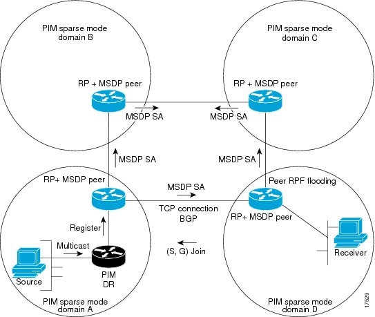
When MSDP is implemented, the following sequence of events occurs:
When a PIM designated device (DR) registers a source with its RP as illustrated in the figure, the RP sends a Source-Active (SA) message to all of its MSDP peers.
Note |
The DR sends the encapsulated data to the RP only once per source (when the source goes active). If the source times out, this process happens again when it goes active again. This situation is different from the periodic SA message that contains all sources that are registered to the originating RP. Those SA messages are MSDP control packets, and, thus, do not contain encapsulated data from active sources. |
The SA message identifies the source address, the group that the source is sending to, and the address or the originator ID of the RP, if configured.
Each MSDP peer that receives the SA message floods the SA message to all of its peers downstream from the originator. In some cases (such as the case with the RPs in PIM-SM domains B and C in the figure), an RP may receive a copy of an SA message from more than one MSDP peer. To prevent looping, the RP consults the BGP next-hop database to determine the next hop toward the originator of the SA message. If both MBGP and unicast BGP are configured, MBGP is checked first, and then unicast BGP. That next-hop neighbor is the RPF-peer for the originator. SA messages that are received from the originator on any interface other than the interface to the RPF peer are dropped. The SA message flooding process, therefore, is referred to as peer-RPF flooding. Because of the peer-RPF flooding mechanism, BGP or MBGP must be running in conjunction with MSDP.
When an RP receives an SA message, it checks to see whether there are any members of the advertised groups in its domain by checking to see whether there are interfaces on the group’s (*, G) outgoing interface list. If there are no group members, the RP does nothing. If there are group members, the RP sends an (S, G) join toward the source. As a result, a branch of the interdomain source tree is constructed across autonomous system boundaries to the RP. As multicast packets arrive at the RP, they are then forwarded down its own shared tree to the group members in the RP’s domain. The members’ DRs then have the option of joining the rendezvous point tree (RPT) to the source using standard PIM-SM procedures.
The originating RP continues to send periodic SA messages for the (S, G) state every 60 seconds for as long as the source is sending packets to the group. When an RP receives an SA message, it caches the SA message. Suppose, for example, that an RP receives an SA message for (172.16.5.4, 228.1.2.3) from originating RP 10.5.4.3. The RP consults its mroute table and finds that there are no active members for group 228.1.2.3, so it passes the SA message to its peers downstream of 10.5.4.3. If a host in the domain then sends a join to the RP for group 228.1.2.3, the RP adds the interface toward the host to the outgoing interface list of its (*, 224.1.2.3) entry. Because the RP caches SA messages, the device will have an entry for (172.16.5.4, 228.1.2.3) and can join the source tree as soon as a host requests a join.
Note |
In all current and supported software releases, caching of MSDP SA messages is mandatory and cannot be manually enabled or disabled. By default, when an MSDP peer is configured, the ip multicast cache-sa-state command will automatically be added to the running configuration. |
MSDP has these benefits:
It breaks up the shared multicast distribution tree. You can make the shared tree local to your domain. Your local members join the local tree, and join messages for the shared tree never need to leave your domain.
PIM sparse-mode domains can rely only on their own RPs, decreasing reliance on RPs in another domain. This increases security because you can prevent your sources from being known outside your domain.
Domains with only receivers can receive data without globally advertising group membership.
Global source multicast routing table state is not required, saving memory.
A stub autonomous system also might want to have MSDP peerings with more than one RP for the sake of redundancy. For example, SA messages cannot just be accepted from multiple default peers, because there is no RPF check mechanism. Instead, SA messages are accepted from only one peer. If that peer fails, SA messages are then accepted from the other peer. The underlying assumption here, of course, is that both default peers are sending the same SA messages.
The figure illustrates a scenario where default MSDP peers might be used. In the figure, a customer that owns Device B is connected to the Internet through two Internet service providers (ISPs), one that owns Device A and the other that owns Device C. They are not running BGP or MBGP between them. In order for the customer to learn about sources in the ISP domain or in other domains, Device B identifies Device A as its default MSDP peer. Device B advertises SA messages to both Device A and Device C, but accepts SA messages either from Device A only or Device C only. If Device A is the first default peer in the configuration, it will be used if it is up and running. Only if Device A is not running will Device B accept SA messages from Device C.
The ISP will also likely use a prefix list to define which prefixes it will accept from the customer device. The customer will define multiple default peers, each having one or more prefixes associated with it.
The customer has two ISPs to use. The customer defines both ISPs as default peers. As long as the first default peer identified in the configuration is up and running, it will be the default peer and the customer will accept all SA messages it receives from that peer.

Device B advertises SAs to Device A and Device C, but uses only Device A or Device C to accept SA messages. If Device A is first in the configuration, it will be used if it is up and running. Only when Device A is not running will Device B accept SAs from Device C. This is the behavior without a prefix list.
If you specify a prefix list, the peer will be a default peer only for the prefixes in the list. You can have multiple active default peers when you have a prefix list associated with each. When you do not have any prefix lists, you can configure multiple default peers, but only the first one is the active default peer as long as the device has connectivity to this peer and the peer is alive. If the first configured peer goes down or the connectivity to this peer goes down, the second configured peer becomes the active default, and so on.
An MSDP mesh group is a group of MSDP speakers that have fully meshed MSDP connectivity between one another. In other words, each of the MSDP peers in the group must have an MSDP peering relationship (MSDP connection) to every other MSDP peer in the group. When an MSDP mesh group is configured between a group of MSDP peers, SA message flooding is reduced. Because when an MSDP peer in the group receives an SA message from another MSDP peer in the group, it assumes that this SA message was sent to all the other MSDP peers in the group. As a result, it is not necessary for the receiving MSDP peer to flood the SA message to the other MSDP peers in the group.
Optimizes SA flooding--MSDP mesh groups are particularly useful for optimizing SA flooding when two or more peers are in a group.
Reduces the amount of SA traffic across the Internet--When MSDP mesh groups are used, SA messages are not flooded to other mesh group peers.
Eliminates RPF checks on arriving SA messages--When an MSDP mesh group is configured, SA messages are always accepted from mesh group peers.
By default, an RP that is configured to run MSDP will originate SA messages for all local sources for which it is the RP. Local sources that register with an RP, therefore, will be advertised in SA messages, which in some cases is not desirable. For example, if sources inside a PIM-SM domain are using private addresses (for example, network 10.0.0.0/8), you should configure an SA origination filter to restrict those addresses from being advertised to other MSDP peers across the Internet.
To control what sources are advertised in SA messages, you can configure SA origination filters on an RP. By creating SA origination filters, you can control the sources advertised in SA messages as follows:
You can configure an RP to prevent the device from advertising local sources in SA messages. The device will still forward SA messages from other MSDP peers in the normal fashion; it will just not originate any SA messages for local sources.
You can configure the device to only originate SA messages for local sources sending to specific groups that match (S, G) pairs defined in the extended access list. All other local sources will not be advertised in SA messages.
You can configure the device to only originate SA messages for local sources sending to specific groups that the match AS paths defined in an AS-path access list. All other local sources will not be advertised in SA messages.
You can configure the device to only originate SA messages for local sources that match the criteria defined in the route map. All other local sources will not be advertised in SA messages.
You configure an SA origination filter that includes an extended access list, an AS-path access list, and route map, or a combination thereof. In this case, all conditions must be true before any local sources are advertised in SA messages.
By default, an MSDP-enabled device forwards all SA messages it receives to all of its MSDP peers. However, you can prevent SA messages from being forwarded to MSDP peers by creating outgoing filter lists. Outgoing filter lists apply to all SA messages, whether locally originated or received from another MSDP peer, whereas SA origination filters apply only to locally originated SA messages. For more information about enabling a filter for MSDP SA messages originated by the local device, see the Controlling SA Messages Originated by an RP for Local Sources section.
By creating an outgoing filter list, you can control the SA messages that a device forwards to a peer as follows:
You can filter all outgoing SA messages forwarded to a specified MSDP peer by configuring the device to stop forwarding its SA messages to the MSDP peer.
You can filter a subset of outgoing SA messages forwarded to a specified MSDP peer based on (S, G) pairs defined in an extended access list by configuring the device to only forward SA messages to the MSDP peer that match the (S, G) pairs permitted in an extended access list. The forwarding of all other SA messages to the MSDP peer will be stopped.
You can filter a subset of outgoing SA messages forwarded to a specified MSDP peer based on match criteria defined in a route map by configuring the device to only forward SA messages that match the criteria defined in the route map. The forwarding of all other SA messages to the MSDP peer will be stopped.
You can filter a subset of outgoing SA messages from a specified peer based on the announcing RP address contained in the SA message by configuring the device to filter outgoing SA messages based on their origin, even after an SA message has been transmitted across one or more MSDP peers. The forwarding of all other SA messages to the MSDP peer will be stopped.
You can configure an outgoing filter list that includes an extended access list, a route map, and either an RP access list or an RP route map. In this case, all conditions must be true for the MSDP peer to forward the outgoing SA message.
 Caution |
Arbitrary filtering of SA messages can result in downstream MSDP peers being starved of SA messages for legitimate active sources. Care, therefore, should be taken when using these sorts of filters. Normally, outgoing filter lists are used only to reject undesirable sources, such as sources using private addresses. |
By default, an MSDP-enabled device receives all SA messages sent to it from its MSDP peers. However, you can control the source information that a device receives from its MSDP peers by creating incoming filter lists.
By creating incoming filter lists, you can control the incoming SA messages that a device receives from its peers as follows:
You can filter all incoming SA messages from a specified MSDP peer by configuring the device to ignore all SA messages sent to it from the specified MSDP peer.
You can filter a subset of incoming SA messages from a specified peer based on (S, G) pairs defined in an extended access list by configuring the device to only receive SA messages from the MSDP peer that match the (S, G) pairs defined in the extended access list. All other incoming SA messages from the MSDP peer will be ignored.
You can filter a subset of incoming SA request messages from a specified peer based on match criteria defined in a route map by configuring the device to only receive SA messages that match the criteria defined in the route map. All other incoming SA messages from the MSDP peer will be ignored.
You can filter a subset of incoming SA messages from a specified peer based on both (S, G) pairs defined in an extended access list and on match criteria defined in a route map by configuring the device to only receive incoming SA messages that both match the (S, G) pairs defined in the extended access list and match the criteria defined in the route map. All other incoming SA messages from the MSDP peer will be ignored.
You can filter a subset of incoming SA messages from a specified peer based on the announcing RP address contained in the SA message by configuring the device to filter incoming SA messages based on their origin, even after the SA message may have already been transmitted across one or more MSDP peers.
You can configure an incoming filter list that includes an extended access list, a route map, and either an RP access list or an RP route map. In this case, all conditions must be true for the MSDP peer to receive the incoming SA message.
Caution |
Arbitrary filtering of SA messages can result in downstream MSDP peers being starved of SA messages for legitimate active sources. Care, therefore, should be taken when using these sorts of filters. Normally, incoming filter lists are used only to reject undesirable sources, such as sources using private addresses. |
The time-to-live (TTL) value provides a means to limit the number of hops a packet can take before being dropped. The ip multicast ttl-threshold command is used to specify a TTL for data-encapsulated SA messages sent to specified MSDP peers. By default, multicast data packets in SA messages are sent to an MSDP peer, provided the TTL value of the packet is greater than 0, which is standard TTL behavior.
In general, a TTL-threshold problem can be introduced by the encapsulation of a source’s initial multicast packet in an SA message. Because the multicast packet is encapsulated inside of the unicast SA message (whose TTL is 255), its TTL is not decremented as the SA message travels to the MSDP peer. Furthermore, the total number of hops that the SA message traverses can be drastically different than a normal multicast packet because multicast and unicast traffic may follow completely different paths to the MSDP peer and hence the remote PIM-SM domain. As a result, encapsulated packets can end up violating TTL thresholds. The solution to this problem is to configure a TTL threshold that is associated with any multicast packet that is encapsulated in an SA message sent to a particular MSDP peer using the ip multicast ttl-threshold command. The ip msdp ttl-threshold command prevents any multicast packet whose TTL in the IP header is less than the TTL value specified for the ttl-value argument from being encapsulated in SA messages sent to that peer.
There are four basic MSDP message types, each encoded in their own Type, Length, and Value (TLV) data format.
SA messages are used to advertise active sources in a domain. In addition, these SA messages may contain the initial multicast data packet that was sent by the source.
SA messages contain the IP address of the originating RP and one or more (S, G) pairs being advertised. In addition, the SA message may contain an encapsulated data packet.
SA request messages are used to request a list of active sources for a specific group. These messages are sent to an MSDP SA cache that maintains a list of active (S, G) pairs in its SA cache. Join latency can be reduced by using SA request messages to request the list of active sources for a group instead of having to wait up to 60 seconds for all active sources in the group to be readvertised by originating RPs.
SA response messages are sent by the MSDP peer in response to an SA request message. SA response messages contain the IP address of the originating RP and one or more (S, G) pairs of the active sources in the originating RP’s domain that are stored in the cache.
Keepalive messages are sent every 60 seconds in order to keep the MSDP session active. If no keepalive messages or SA messages are received for 75 seconds, the MSDP session is reset.
MSDP is not enabled, and no default MSDP peer exists.
How to Configure MSDP
Configure an MSDP peer.
| Command or Action | Purpose | |
|---|---|---|
| Step 1 |
enable Example: |
Enables privileged EXEC mode.
|
| Step 2 |
configure terminal Example: |
Enters global configuration mode. |
| Step 3 |
ip msdp default-peer ip-address | name [prefix-list list] Example: |
Defines a default peer from which to accept all MSDP SA messages.
|
| Step 4 |
ip prefix-list name [description string] | seq number {permit | deny} network length Example: |
(Optional) Creates a prefix list using the name specified in Step 2.
|
| Step 5 |
ip msdp description {peer-name | peer-address} text Example: |
(Optional) Configures a description for the specified peer to make it easier to identify in a configuration or in show command output. By default, no description is associated with an MSDP peer. |
| Step 6 |
end Example: |
Returns to privileged EXEC mode. |
| Step 7 |
show running-config Example: |
Verifies your entries. |
| Step 8 |
copy running-config startup-config Example: |
(Optional) Saves your entries in the configuration file. |
If you want to sacrifice some memory in exchange for reducing the latency of the source information, you can configure the Switch to cache SA messages. Perform the following steps to enable the caching of source/group pairs:
Follow these steps to enable the caching of source/group pairs:
| Command or Action | Purpose | |||
|---|---|---|---|---|
| Step 1 |
enable Example: |
Enables privileged EXEC mode.
|
||
| Step 2 |
configure terminal Example: |
Enters global configuration mode. |
||
| Step 3 |
ip msdp cache-sa-state [list access-list-number] Example: |
Enables the caching of source/group pairs (create an SA state). Those pairs that pass the access list are cached. For list access-list-number , the range is 100 to 199.
|
||
| Step 4 |
access-list access-list-number {deny | permit} protocol source source-wildcard destination destination-wildcard Example: |
Creates an IP extended access list, repeating the command as many times as necessary.
Recall that the access list is always terminated by an implicit deny statement for everything. |
||
| Step 5 |
end Example: |
Returns to privileged EXEC mode. |
||
| Step 6 |
show running-config Example: |
Verifies your entries. |
||
| Step 7 |
copy running-config startup-config Example: |
(Optional) Saves your entries in the configuration file. |
If you want a new member of a group to learn the active multicast sources in a connected PIM sparse-mode domain that are sending to a group, perform this task for the Switch to send SA request messages to the specified MSDP peer when a new member joins a group. The peer replies with the information in its SA cache. If the peer does not have a cache configured, this command has no result. Configuring this feature reduces join latency but sacrifices memory.
Follow these steps to configure the Switch to send SA request messages to the MSDP peer when a new member joins a group and wants to receive multicast traffic:
| Command or Action | Purpose | |
|---|---|---|
| Step 1 |
enable Example: |
Enables privileged EXEC mode.
|
| Step 2 |
configure terminal Example: |
Enters global configuration mode. |
| Step 3 |
ip msdp sa-request {ip-address | name} Example: |
Configure the Switch to send SA request messages to the specified MSDP peer. For ip-address | name , enter the IP address or name of the MSDP peer from which the local Switch requests SA messages when a new member for a group becomes active. Repeat the command for each MSDP peer that you want to supply with SA messages. |
| Step 4 |
end Example: |
Returns to privileged EXEC mode. |
| Step 5 |
show running-config Example: |
Verifies your entries. |
| Step 6 |
copy running-config startup-config Example: |
(Optional) Saves your entries in the configuration file. |
You can control the multicast source information that originates with your Switch:
Sources you advertise (based on your sources)
Receivers of source information (based on knowing the requestor)
For more information, see the Redistributing Sources and the Filtering Source-Active Request Messages.
SA messages originate on RPs to which sources have registered. By default, any source that registers with an RP is advertised. The A flag is set in the RP when a source is registered, which means the source is advertised in an SA unless it is filtered.
Follow these steps to further restrict which registered sources are advertised:
| Command or Action | Purpose | |
|---|---|---|
| Step 1 |
enable Example: |
Enables privileged EXEC mode.
|
| Step 2 |
configure terminal Example: |
Enters global configuration mode. |
| Step 3 |
ip msdp redistribute [list access-list-name] [asn aspath-access-list-number] [route-map map] Example: |
Configures which (S,G) entries from the multicast routing table are advertised in SA messages. By default, only sources within the local domain are advertised.
The Switch advertises (S,G) pairs according to the access list or autonomous system path access list. |
| Step 4 |
Use one of the following:
Example:or |
Creates an IP standard access list, repeating the command as many times as necessary. or Creates an IP extended access list, repeating the command as many times as necessary.
Recall that the access list is always terminated by an implicit deny statement for everything. |
| Step 5 |
end Example: |
Returns to privileged EXEC mode. |
| Step 6 |
show running-config Example: |
Verifies your entries. |
| Step 7 |
copy running-config startup-config Example: |
(Optional) Saves your entries in the configuration file. |
By default, only Switch that are caching SA information can respond to SA requests. By default, such a Switch honors all SA request messages from its MSDP peers and supplies the IP addresses of the active sources.
However, you can configure the Switch to ignore all SA requests from an MSDP peer. You can also honor only those SA request messages from a peer for groups described by a standard access list. If the groups in the access list pass, SA request messages are accepted. All other such messages from the peer for other groups are ignored.
To return to the default setting, use the no ip msdp filter-sa-request {ip-address| name} global configuration command.
Follow these steps to configure one of these options:
| Command or Action | Purpose | |
|---|---|---|
| Step 1 |
enable Example: |
Enables privileged EXEC mode.
|
| Step 2 |
configure terminal Example: |
Enters global configuration mode. |
| Step 3 |
Use one of the following:
Example: |
Filters all SA request messages from the specified MSDP peer. or Filters SA request messages from the specified MSDP peer for groups that pass the standard access list. The access list describes a multicast group address. The range for the access-list-number is 1 to 99. |
| Step 4 |
access-list access-list-number {deny | permit} source [source-wildcard] Example: |
Creates an IP standard access list, repeating the command as many times as necessary.
Recall that the access list is always terminated by an implicit deny statement for everything. |
| Step 5 |
end Example: |
Returns to privileged EXEC mode. |
| Step 6 |
show running-config Example: |
Verifies your entries. |
| Step 7 |
copy running-config startup-config Example: |
(Optional) Saves your entries in the configuration file. |
By default, the Switch forwards all SA messages it receives to all its MSDP peers. However, you can prevent outgoing messages from being forwarded to a peer by using a filter or by setting a time-to-live (TTL) value.
By creating a filter, you can perform one of these actions:
Filter all source/group pairs
Specify an IP extended access list to pass only certain source/group pairs
Filter based on match criteria in a route map
Follow these steps to apply a filter:
| Command or Action | Purpose | |
|---|---|---|
| Step 1 |
enable Example: |
Enables privileged EXEC mode.
|
| Step 2 |
configure terminal Example: |
Enters global configuration mode. |
| Step 3 |
Use one of the following:
Example:or or |
|
| Step 4 |
access-list access-list-number {deny | permit} protocol source source-wildcard destination destination-wildcard Example: |
(Optional) Creates an IP extended access list, repeating the command as many times as necessary.
Recall that the access list is always terminated by an implicit deny statement for everything. |
| Step 5 |
end Example: |
Returns to privileged EXEC mode. |
| Step 6 |
show running-config Example: |
Verifies your entries. |
| Step 7 |
copy running-config startup-config Example: |
(Optional) Saves your entries in the configuration file. |
You can use a TTL value to control what data is encapsulated in the first SA message for every source. Only multicast packets with an IP-header TTL greater than or equal to the ttl argument are sent to the specified MSDP peer. For example, you can limit internal traffic to a TTL of 8. If you want other groups to go to external locations, you must send those packets with a TTL greater than 8.
Follow these steps to establish a TTL threshold:
| Command or Action | Purpose | |
|---|---|---|
| Step 1 |
enable Example: |
Enables privileged EXEC mode.
|
| Step 2 |
configure terminal Example: |
Enters global configuration mode. |
| Step 3 |
ip msdp ttl-threshold {ip-address | name} ttl Example: |
Limits which multicast data is encapsulated in the first SA message to the specified MSDP peer.
|
| Step 4 |
end Example: |
Returns to privileged EXEC mode. |
| Step 5 |
show running-config Example: |
Verifies your entries. |
| Step 6 |
copy running-config startup-config Example: |
(Optional) Saves your entries in the configuration file. |
By default, the Switch receives all SA messages that its MSDP RPF peers send to it. However, you can control the source information that you receive from MSDP peers by filtering incoming SA messages. In other words, you can configure the Switch to not accept them.
You can perform one of these actions:
Filter all incoming SA messages from an MSDP peer
Specify an IP extended access list to pass certain source/group pairs
Filter based on match criteria in a route map
Follow these steps to apply a filter:
| Command or Action | Purpose | |
|---|---|---|
| Step 1 |
enable Example: |
Enables privileged EXEC mode.
|
| Step 2 |
configure terminal Example: |
Enters global configuration mode. |
| Step 3 |
Use one of the following:
Example:or or |
|
| Step 4 |
access-list access-list-number {deny | permit} protocol source source-wildcard destination destination-wildcard Example: |
(Optional) Creates an IP extended access list, repeating the command as many times as necessary.
Recall that the access list is always terminated by an implicit deny statement for everything. |
| Step 5 |
end Example: |
Returns to privileged EXEC mode. |
| Step 6 |
show running-config Example: |
Verifies your entries. |
| Step 7 |
copy running-config startup-config Example: |
(Optional) Saves your entries in the configuration file. |
Perform this optional task to configure an MSDP mesh group.
Note |
You can configure multiple mesh groups per device. |
| Command or Action | Purpose | |||
|---|---|---|---|---|
| Step 1 |
enable Example: |
Enables privileged EXEC mode. Enter your password, if prompted. |
||
| Step 2 |
configure terminal Example: |
Enters global configuration mode. |
||
| Step 3 |
ip msdp mesh-group mesh-name {peer-address | peer-name } Example: |
Configures an MSDP mesh group and indicates that an MSDP peer belongs to that mesh group.
|
||
| Step 4 |
Repeat Step 3 to add MSDP peers as members of the mesh group. |
-- |
||
| Step 5 |
exit Example: |
Exits global configuration mode and returns to privileged EXEC mode. |
||
| Step 6 |
show running-config Example: |
Verifies your entries. |
||
| Step 7 |
copy running-config startup-config Example: |
(Optional) Saves your entries in the configuration file. |
MSDP is running and the MSDP peers must be configured.
| Command or Action | Purpose | |
|---|---|---|
| Step 1 |
enable Example: |
Enables privileged EXEC mode. Enter your password, if prompted. |
| Step 2 |
configure terminal Example: |
Enters global configuration mode. |
| Step 3 |
ip msdp shutdown {peer-name | peer-address } Example: |
Administratively shuts down the specified MSDP peer. |
| Step 4 |
Repeat Step 3 to shut down additional MSDP peers. |
-- |
| Step 5 |
end Example: |
Exits global configuration mode and returns to privileged EXEC mode. |
| Step 6 |
show running-config Example: |
Verifies your entries. |
| Step 7 |
copy running-config startup-config Example: |
(Optional) Saves your entries in the configuration file. |
You can configure MSDP on a Switch that borders a PIM sparse-mode region with a dense-mode region. By default, active sources in the dense-mode region do not participate in MSDP.
Note |
We do not recommend using the ip msdp border sa-address global configuration command. It is better to configure the border router in the sparse-mode domain to proxy-register sources in the dense-mode domain to the RP of the sparse-mode domain and have the sparse-mode domain use standard MSDP procedures to advertise these sources. |
The ip msdp originator-id global configuration command also identifies an interface to be used as the RP address. If both the ip msdp border sa-address and the ip msdp originator-id global configuration commands are configured, the address derived from the ip msdp originator-id command specifies the RP address.
Follow these steps to configure the border router to send SA messages for sources active in the dense-mode region to the MSDP peers:
| Command or Action | Purpose | |
|---|---|---|
| Step 1 |
enable Example: |
Enables privileged EXEC mode.
|
| Step 2 |
configure terminal Example: |
Enters global configuration mode. |
| Step 3 |
ip msdp border sa-address interface-id Example: |
Configures the switch on the border between a dense-mode and sparse-mode region to send SA messages about active sources in the dense-mode region. For interface-id , specifies the interface from which the IP address is derived and used as the RP address in SA messages. The IP address of the interface is used as the Originator-ID, which is the RP field in the SA message. |
| Step 4 |
ip msdp redistribute [list access-list-name] [asn aspath-access-list-number] [route-map map] Example: |
Configures which (S,G) entries from the multicast routing table are advertised in SA messages. For more information, see the Redistributing Sources. |
| Step 5 |
end Example: |
Returns to privileged EXEC mode. |
| Step 6 |
show running-config Example: |
Verifies your entries. |
| Step 7 |
copy running-config startup-config Example: |
(Optional) Saves your entries in the configuration file. |
Perform this optional task to allow an MSDP speaker that originates an SA message to use the IP address of its interface as the RP address in the SA message.
If you configure multiple devices in an MSDP mesh group for Anycast RP.
If you have a device that borders a PIM-SM domain and a PIM-DM domain. If a device borders a PIM-SM domain and a PIM-DM domain and you want to advertise active sources within the PIM-DM domain, configure the RP address in SA messages to be the address of the originating device’s interface.
MSDP is enabled and the MSDP peers are configured. For more information about configuring MSDP peers, see the Configuring an MSDP Peer section.
| Command or Action | Purpose | |
|---|---|---|
| Step 1 |
enable Example: |
Enables privileged EXEC mode.
|
| Step 2 |
configure terminal Example: |
Enters global configuration mode. |
| Step 3 |
ip msdp originator-id Example: |
Configures the RP address in SA messages to be the address of the originating device’s interface. |
| Step 4 |
exit Example: |
Exits global configuration mode and returns to privileged EXEC mode. |
| Step 5 |
show running-config Example: |
Verifies your entries. |
| Step 6 |
copy running-config startup-config Example: |
(Optional) Saves your entries in the configuration file. |
Monitoring and Maintaining MSDP
Perform this optional task to monitor MSDP SA messages, peers, state, and peer status.
| Step 1 |
enable Example:Enables privileged EXEC mode.
|
| Step 2 |
debug ip msdp [peer-address | peer-name ] [detail ] [routes ] Use this command to debug MSDP activity. Use the optional peer-address or peer-name argument to specify for which peer debug events are logged. The following is sample output from the debug ip msdp command: Example: |
| Step 3 |
debug ip msdp resets Use this command to debug MSDP peer reset reasons. Example: |
| Step 4 |
show ip msdp count [as-number ] Use this command to display the number of sources and groups originated in MSDP SA messages and the number of SA messages from an MSDP peer in the SA cache. The ip msdp cache-sa-state command must be configured for this command to produce any output. The following is sample output from the show ip msdp count command: Example: |
| Step 5 |
show ip msdp peer [peer-address | peer-name ] Use this command to display detailed information about MSDP peers. Use the optional peer-address or peer-name argument to display information about a particular peer. The following is sample output from the show ip msdp peer command: Example: |
| Step 6 |
show ip msdp sa-cache [group-address | source-address | group-name | source-name ] [as-number ] Use this command to display the (S, G) state learned from MSDP peers. The following is sample output from the show ip msdp sa-cache command: Example: |
| Step 7 |
show ip msdp summary Use this command to display MSDP peer status. The following is sample output from the show ip msdp summary command: Example: |
Perform this optional task to clear MSDP connections, statistics, and SA cache entries.
| Command or Action | Purpose | |
|---|---|---|
| Step 1 |
enable Example: |
Enables privileged EXEC mode.
|
| Step 2 |
clear ip msdp peer [peer-address | peer-name ] Example: |
Clears the TCP connection to the specified MSDP peer and resets all MSDP message counters. |
| Step 3 |
clear ip msdp statistics [peer-address | peer-name] Example: |
Clears the statistics counters for the specified MSDP peer and resets all MSDP message counters. |
| Step 4 |
clear ip msdp sa-cache [group-address ] Example: |
Clears SA cache entries.
|
This example shows a partial configuration of Router A and Router C in . Each of these ISPs have more than one customer (like the customer in ) who use default peering (no BGP or MBGP). In that case, they might have similar configurations. That is, they accept SAs only from a default peer if the SA is permitted by the corresponding prefix list.
Router A
Router(config)# ip msdp default-peer 10.1.1.1
Router(config)# ip msdp default-peer 10.1.1.1 prefix-list site-a
Router(config)# ip prefix-list site-b permit 10.0.0.0/1
Router C
Router(config)# ip msdp default-peer 10.1.1.1 prefix-list site-a
Router(config)# ip prefix-list site-b permit 10.0.0.0/1
This example shows how to enable the cache state for all sources in 171.69.0.0/16 sending to groups 224.2.0.0/16:
SwitchDevice(config)# ip msdp cache-sa-state 100
SwitchDevice(config)# access-list 100 permit ip 171.69.0.0 0.0.255.255 224.2.0.0 0.0.255.255
This example shows how to configure the switch to send SA request messages to the MSDP peer at 171.69.1.1:
SwitchDevice(config)# ip msdp sa-request 171.69.1.1
This example shows how to configure the switch to filter SA request messages from the MSDP peer at 171.69.2.2. SA request messages from sources on network 192.4.22.0 pass access list 1 and are accepted; all others are ignored.
SwitchDevice(config)# ip msdp filter sa-request 171.69.2.2 list 1
SwitchDevice(config)# access-list 1 permit 192.4.22.0 0.0.0.255
This example shows how to allow only (S,G) pairs that pass access list 100 to be forwarded in an SA message to the peer named switch.cisco.com :
SwitchDevice(config)# ip msdp peer switch.cisco.com connect-source gigabitethernet1/0/1
SwitchDevice(config)# ip msdp sa-filter out switch.cisco.com list 100
SwitchDevice(config)# access-list 100 permit ip 171.69.0.0 0.0.255.255 224.20 0 0.0.255.255
This example shows how to filter all SA messages from the peer named switch.cisco.com :
SwitchDevice(config)# ip msdp peer switch.cisco.com connect-source gigabitethernet1/0/1
SwitchDevice(config)# ip msdp sa-filter in switch.cisco.com
The following example shows how to configure three devices to be fully meshed members of an MSDP mesh group:
ip msdp peer 10.2.2.2
ip msdp peer 10.3.3.3
ip msdp mesh-group test-mesh-group 10.2.2.2
ip msdp mesh-group test-mesh-group 10.3.3.3
ip msdp peer 10.1.1.1
ip msdp peer 10.3.3.3
ip msdp mesh-group test-mesh-group 10.1.1.1
ip msdp mesh-group test-mesh-group 10.3.3.3
ip msdp peer 10.1.1.1
ip msdp peer 10.2.2.2
ip msdp mesh-group test-mesh-group 10.1.1.1
ip msdp mesh-group test-mesh-group 10.2.2.2This example shows how to configure the switch to send SA request messages to the MSDP peer at 171.69.1.1:
SwitchDevice(config)# ip msdp sa-request 171.69.1.1
 Feedback