Configuring the Switch
Use the following sections to configure the switch.
Configuring Switch Details
The Configuration > Switch > Switch page allows you to configure access to the switch.

Procedure
| Step 1 |
In the Hostname field, enter a hostname to identify your device on the network. It is case sensitive, can be alphanumeric, include special characters, and extend upto 32 characters. |
||||||||||
| Step 2 |
In the Switch Management Interface section, perform the following tasks to manage the switch remotely.
|
||||||||||
| Step 3 |
Enter the address of the interface through which the switch connects to the network in the Default Gateway field. |
||||||||||
| Step 4 |
Set the Maximum Transmission Unit (MTU) size in the MTU Size field. It is the largest sized packet that your device can send. If the connected router cannot handle a large MTU, packets may be retransmitted. A small MTU may result in a higher number of packets and cause overheads and performance limitations. The default value is 1500 bytes. |
||||||||||
| Step 5 |
Click Apply to save your changes. |
Configuring STP
Spanning Tree Protocol (STP) is a network protocol that builds a logical loop-free topology for Ethernet networks.
The Configuration > Switch > STP page displays all the logical interfaces configured on your device. The default STP mode is RPVST.

Procedure
| Step 1 |
From the STP Mode drop-down list, choose the STP mode for your device. Your device supports MST, PVST, and RPVST STP modes. |
| Step 2 |
In the STP Port Types drop-down list, select among Normal, Edge, or Network to enable portfast edge. MorePortFast causes the switch to enter the spanning tree forwarding state immediately, bypassing the listening and learning states. |
| Step 3 |
Select the interface for which you want to set the STP mode. |
| Step 4 |
Set the Edge-BPDU Filter toggle button to Enable to prevent the system from sending or even receiving BPDUs on specified ports. MoreSwitches send and receive spanning-tree frames, called bridge protocol data units (BPDUs), at regular intervals to ensure a loop-free path. |
| Step 5 |
Set the Edge-BPDU Guard toggle button to Enable to move a non-trunking port into an err-disable state when a BPDU is received on that port. MoreWhen you enable BPDU guard on the switch, spanning tree shuts down PortFast-configured interfaces that receive BPDUs instead of putting them into the spanning tree blocking state. |
| Step 6 |
Set the STP Loopguard toggle button to Enable to enable loopguard on the ports. MoreLoop guard helps prevent bridging loops that could occur because of a unidirectional link failure on a point-to-point link. It detects root ports and blocked ports and ensures that they keep receiving BPDUs from their designated port on the segment. |
| Step 7 |
Use the Transmit Hold-Count drop-down list to change the number of BPDUs that can be sent. |
| Step 8 |
To modify the bridge priority number, click the VLAN record in the list. Choose a new bridge priority number from the drop-down list. To learn the topology of the network, STP-enabled switches communicate with each other using standardized data messages called BPDUs. Using BPDUs, the switch with the smallest bridge priority number is automatically elected as the root bridge. If the bridge priority is the same on all the switches then the switch with the smaller MAC address is elected as the root bridge. Each switch then elects port that are designated and that can communicate with th root bridge and forward traffic. Non-designated ports block traffic. A port normally starts in Blocking state, and then immediately moves through to the Listening state. In the Listening state, the device determines if the port is part of a physical loop. If it is, the port state is changed back to Blocking, and no data is sent or received on the port. If the port is not part of a loop, the port proceeds to the Learning state, and learns the MAC addresses in the frame. The port then moves into Forwarding state ready to send and receive data. |
| Step 9 |
Click Apply. |
Configuring VTP
VTP reduces administration in a switched network. When you configure a new VLAN on one VTP server, the VLAN is distributed through all switches in the domain. This reduces the need to configure the same VLAN everywhere.
From the Configuration > Switch > VTP page:

Procedure
| Step 1 |
Enter a VTP administrative Domain name. The name can be 1 to 32 characters. All switches operating in VTP server or client mode under the same administrative responsibility must be configured with the same domain name. |
| Step 2 |
Enter the password for the VTP domain. The password can be 8 to 64 characters. If you configure a VTP password, the VTP domain does not function properly if you do not assign the same password to each switch in the domain. |
| Step 3 |
Select the version from the Version drop-down list. Version 3, provides enhanced authentication, support for extended range VLAN (VLANs 1006 to 4094) database propagation and support for any database in a domain for e.g. propagating Multiple Spanning Tree (MST) protocol database information. |
| Step 4 |
From the VLAN Mode select:
|
| Step 5 |
From the MST Mode, select from the drop-down list. If you select server, this switch can be configured as the primary server for MST protocol database. |
| Step 6 |
Select the Pruning Mode checkbox to configure the domain to allow pruning. |
| Step 7 |
Click Apply to save the changes. |
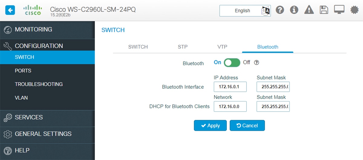
Enabling Bluetooth
The switch can be configured and managed over the air with Bluetooth. The switch supports an external Bluetooth dongle that plugs into the USB port on the switch and allows Bluetooth based RF connection with external Laptops and Tablets.
The Configuration > Switch > Bluetooth tab is displayed only if your device supports Bluetooth. When your device boots up for the first time or after a factory reset, Bluetooth is enabled by default. However, immediately after the initial setup configuration is loaded, Bluetooth is disabled.
Procedure
| Step 1 |
Set the Bluetooth field to On. The Bluetooth Interface Status indicates whether transfer through Bluetooth is possible or not. |
| Step 2 |
Enter the IP Address and the Subnet Mask for the Bluetooth interface. |
| Step 3 |
Enter the DHCP Server network address and the Subnet Mask for the Bluetooth interface. A new DHCP pool is created which is used to assign IP addresses to clients connecting through the Bluetooth interface. The Bluetooth interface IP address should ideally be the first IP address from this pool. |


 Feedback