- Index
- Preface
- Overview
- Using the Command-Line Interface
- Getting Started with CMS
- Assigning the Switch IP Address and Default Gateway
- Managing Switch Stacks
- Clustering Switches
- Administering the Switch
- Configuring 802.1X Port-Based Authentication
- Configuring Interface Characteristics
- Configuring VLANs
- Configuring VTP
- Configuring Voice VLAN
- Configuring STP
- Configuring Optional Spanning-Tree Features
- Configuring IGMP Snooping and MVR
- Configuring Port-Based Traffic Control
- Configuring CDP
- Configuring UDLD
- Configuring SPAN and RSPAN
- Configuring RMON
- Configuring System Message Logging
- Configuring SNMP
- Configuring Network Security with ACLs
- Configuring QoS
- Configuring EtherChannels
- Configuring IP Unicast Routing
- Configuring HSRP
- Configuring IP Multicast Routing
- Configuring MSDP
- Configuring Fallback Bridging
- Troubleshooting
- Supported MIBs
- Working with the IOS File System, Configuration Files, and Software Images
- Unsupported Commands for Release 12.1(11)AX
Catalyst 3750 Switch Software Configuration Guide, 12.1(11)AX
Bias-Free Language
The documentation set for this product strives to use bias-free language. For the purposes of this documentation set, bias-free is defined as language that does not imply discrimination based on age, disability, gender, racial identity, ethnic identity, sexual orientation, socioeconomic status, and intersectionality. Exceptions may be present in the documentation due to language that is hardcoded in the user interfaces of the product software, language used based on RFP documentation, or language that is used by a referenced third-party product. Learn more about how Cisco is using Inclusive Language.
- Updated:
- August 3, 2007
Chapter: Configuring QoS
- Understanding QoS
- Configuring QoS
Configuring QoS
This chapter describes how to configure quality of service (QoS) on the Catalyst 3750 switch. With this feature, you can provide preferential treatment to certain traffic at the expense of others. Without QoS, the switch offers best-effort service to each packet, regardless of the packet contents or size. It sends the packets without any assurance of reliability, delay bounds, or throughput. Unless otherwise noted, the term switch refers to a standalone switch and a switch stack.

Note ![]() For complete syntax and usage information for the commands used in this chapter, refer to the command reference this release.
For complete syntax and usage information for the commands used in this chapter, refer to the command reference this release.
This chapter consists of these sections:
Understanding QoS
Typically, networks operate on a best-effort delivery basis, which means that all traffic has equal priority and an equal chance of being delivered in a timely manner. When congestion occurs, all traffic has an equal chance of being dropped.
When you configure the QoS feature, you can select specific network traffic, prioritize it according to its relative importance, and use congestion-management and congestion-avoidance techniques to provide preferential treatment. Implementing QoS in your network makes network performance more predictable and bandwidth utilization more effective.
The QoS implementation is based on the Differentiated Services (Diff-Serv) architecture, an emerging standard from the Internet Engineering Task Force (IETF). This architecture specifies that each packet is classified upon entry into the network.
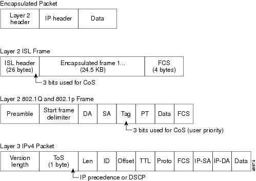
The classification is carried in the IP packet header, using 6 bits from the deprecated IP type of service (TOS) field to carry the classification (class) information. Classification can also be carried in the Layer 2 frame. These special bits in the Layer 2 frame or a Layer 3 packet are described here and shown in Figure 24-1:
•![]() Prioritization bits in Layer 2 frames:
Prioritization bits in Layer 2 frames:
Layer 2 Inter-Switch Link (ISL) frame headers have a 1-byte User field that carries an IEEE 802.1P class of service (CoS) value in the three least-significant bits. On interfaces configured as Layer 2 ISL trunks, all traffic is in ISL frames.
Layer 2 802.1Q frame headers have a 2-byte Tag Control Information field that carries the CoS value in the three most-significant bits, which are called the User Priority bits. On interfaces configured as Layer 2 802.1Q trunks, all traffic is in 802.1Q frames except for traffic in the native VLAN.
Other frame types cannot carry Layer 2 CoS values.
Layer 2 CoS values range from 0 for low priority to 7 for high priority.
•![]() Prioritization bits in Layer 3 packets:
Prioritization bits in Layer 3 packets:
Layer 3 IP packets can carry either an IP precedence value or a Differentiated Services Code Point (DSCP) value. QoS supports the use of either value because DSCP values are backward-compatible with IP precedence values.
IP precedence values range from 0 to 7.
DSCP values range from 0 to 63.
Figure 24-1 QoS Classification Layers in Frames and Packets
Note ![]() Layer 3 IPv6 packets are treated as non-IP packets and are bridged by the switch.
Layer 3 IPv6 packets are treated as non-IP packets and are bridged by the switch.
All switches and routers that access the Internet rely on the class information to provide the same forwarding treatment to packets with the same class information and different treatment to packets with different class information. The class information in the packet can be assigned by end hosts or by switches or routers along the way, based on a configured policy, detailed examination of the packet, or both. Detailed examination of the packet is expected to happen closer to the edge of the network so that the core switches and routers are not overloaded with this task.
Switches and routers along the path can use the class information to limit the amount of resources allocated per traffic class. The behavior of an individual device when handling traffic in the DiffServ architecture is called per-hop behavior. If all devices along a path provide a consistent per-hop behavior, you can construct an end-to-end QoS solution.
Implementing QoS in your network can be a simple or complex task and depends on the QoS features offered by your internetworking devices, the traffic types and patterns in your network, and the granularity of control that you need over incoming and outgoing traffic.
Basic QoS Model
To implement QoS, the switch must distinguish packets or flow from one another (classify), assign a label to indicate the given quality of service as the packets move through the switch, make the packets comply with the configured resource usage limits (police and mark), and provide different treatment (queue and schedule) in all situations where resource contention exists. The switch also needs to ensure that traffic sent from it meets a specific traffic profile (shape).
Figure 24-2 shows the basic QoS model. Actions at the ingress interface include classifying traffic, policing, marking, queueing, and scheduling:
•![]() Classification is the process of generating a distinct path for a packet by associating it with a QoS label. The switch maps the CoS or DSCP in the packet to a QoS label to distinguish one kind of traffic from another. The QoS label that is generated identifies all future QoS actions to be performed on this packet. For more information, see the "Classification" section.
Classification is the process of generating a distinct path for a packet by associating it with a QoS label. The switch maps the CoS or DSCP in the packet to a QoS label to distinguish one kind of traffic from another. The QoS label that is generated identifies all future QoS actions to be performed on this packet. For more information, see the "Classification" section.
•![]() Policing determines whether a packet is in or out of profile by comparing the rate of the incoming traffic to the configured policer. The policer limits the bandwidth consumed by a flow of traffic. The result of this determination is passed to the marker. For more information, see the "Policing and Marking" section.
Policing determines whether a packet is in or out of profile by comparing the rate of the incoming traffic to the configured policer. The policer limits the bandwidth consumed by a flow of traffic. The result of this determination is passed to the marker. For more information, see the "Policing and Marking" section.
•![]() Marking evaluates the policer and configuration information for the action to be taken when a packet is out of profile and decides what to do with the packet (pass through a packet without modification, mark down the QoS label in the packet, or drop the packet). For more information, see the "Policing and Marking" section.
Marking evaluates the policer and configuration information for the action to be taken when a packet is out of profile and decides what to do with the packet (pass through a packet without modification, mark down the QoS label in the packet, or drop the packet). For more information, see the "Policing and Marking" section.
•![]() Queueing evaluates the QoS label and the corresponding DSCP or CoS value to determine into which of the two ingress queues to place a packet. Queueing is enhanced with the weighted tail-drop (WTD) algorithm, a congestion-avoidance mechanism. If the threshold is exceeded, the packet is dropped. For more information, see the "Queueing and Scheduling Overview" section.
Queueing evaluates the QoS label and the corresponding DSCP or CoS value to determine into which of the two ingress queues to place a packet. Queueing is enhanced with the weighted tail-drop (WTD) algorithm, a congestion-avoidance mechanism. If the threshold is exceeded, the packet is dropped. For more information, see the "Queueing and Scheduling Overview" section.
•![]() Scheduling services the queues based on their configured shaped round robin (SRR) weights. One of the ingress queues is the priority queue, and SRR services it for its configured share before servicing the other queue. For more information, see the "SRR Shaping and Sharing" section.
Scheduling services the queues based on their configured shaped round robin (SRR) weights. One of the ingress queues is the priority queue, and SRR services it for its configured share before servicing the other queue. For more information, see the "SRR Shaping and Sharing" section.
Actions at the egress interface include queueing and scheduling:
•![]() Queueing evaluates the QoS label and the corresponding DSCP or CoS value to determine into which of the four egress queues to place a packet. Because congestion can occur when multiple ingress ports simultaneously send data to an egress port, WTD is used to differentiate traffic classes and to subject the packets to different thresholds based on the QoS label. If the threshold is exceeded, the packet is dropped. For more information, see the "Queueing and Scheduling Overview" section.
Queueing evaluates the QoS label and the corresponding DSCP or CoS value to determine into which of the four egress queues to place a packet. Because congestion can occur when multiple ingress ports simultaneously send data to an egress port, WTD is used to differentiate traffic classes and to subject the packets to different thresholds based on the QoS label. If the threshold is exceeded, the packet is dropped. For more information, see the "Queueing and Scheduling Overview" section.
•![]() Scheduling services the four egress queues based on their configured SRR shared or shaped weights.
Scheduling services the four egress queues based on their configured SRR shared or shaped weights.
Figure 24-2 Basic QoS Model

Classification
Classification is the process of distinguishing one kind of traffic from another by examining the fields in the packet. Classification is enabled only if QoS is globally enabled on the switch. By default, QoS is globally disabled, so no classification occurs.
Note ![]() Classification occurs only on a physical interface basis. No support exists for classifying packets at the VLAN or the switch virtual interface level.
Classification occurs only on a physical interface basis. No support exists for classifying packets at the VLAN or the switch virtual interface level.
During classification, the switch performs a lookup and assigns a QoS label to the packet. The QoS label identifies all QoS actions to be performed on the packet and from which queue the packet is sent.
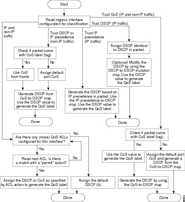
The QoS label is based on the DSCP or the CoS value in the packet and determines the queueing and scheduling actions to perform on the packet. The label is mapped according to the trust setting and the packet type as shown in Figure 24-3.
You specify which fields in the frame or packet that you want to use to classify incoming traffic. For non-IP traffic, you have these classification options as shown in Figure 24-3:
•![]() Trust the CoS value in the incoming frame (configure the port to trust CoS). Then use the configurable CoS-to-DSCP map to generate a DSCP value for the packet. Layer 2 ISL frame headers carry the CoS value in the three least-significant bits of the 1-byte User field. Layer 2 802.1Q frame headers carry the CoS value in the three most-significant bits of the Tag Control Information field. CoS values range from 0 for low priority to 7 for high priority.
Trust the CoS value in the incoming frame (configure the port to trust CoS). Then use the configurable CoS-to-DSCP map to generate a DSCP value for the packet. Layer 2 ISL frame headers carry the CoS value in the three least-significant bits of the 1-byte User field. Layer 2 802.1Q frame headers carry the CoS value in the three most-significant bits of the Tag Control Information field. CoS values range from 0 for low priority to 7 for high priority.
•![]() Trust the DSCP or trust IP precedence value in the incoming frame. These configurations are meaningless for non-IP traffic. If you configure a port with either of these options and non-IP traffic is received, the switch assigns a CoS value and generates a DSCP value from the CoS-to-DSCP map.
Trust the DSCP or trust IP precedence value in the incoming frame. These configurations are meaningless for non-IP traffic. If you configure a port with either of these options and non-IP traffic is received, the switch assigns a CoS value and generates a DSCP value from the CoS-to-DSCP map.
•![]() Perform the classification based on a configured Layer 2 MAC access control list (ACL), which can examine the MAC source address, the MAC destination address, and other fields. If no ACL is configured, the packet is assigned 0 as the DSCP and CoS values, which means best-effort traffic. Otherwise, the policy-map action specifies a DSCP or CoS value to assign to the incoming frame.
Perform the classification based on a configured Layer 2 MAC access control list (ACL), which can examine the MAC source address, the MAC destination address, and other fields. If no ACL is configured, the packet is assigned 0 as the DSCP and CoS values, which means best-effort traffic. Otherwise, the policy-map action specifies a DSCP or CoS value to assign to the incoming frame.
For IP traffic, you have these classification options as shown in Figure 24-3:
•![]() Trust the DSCP value in the incoming packet (configure the port to trust DSCP), and assign the same DSCP value to the packet. The IETF defines the six most-significant bits of the 1-byte TOS field as the DSCP. The priority represented by a particular DSCP value is configurable. DSCP values range from 0 to 63.
Trust the DSCP value in the incoming packet (configure the port to trust DSCP), and assign the same DSCP value to the packet. The IETF defines the six most-significant bits of the 1-byte TOS field as the DSCP. The priority represented by a particular DSCP value is configurable. DSCP values range from 0 to 63.
For ports that are on the boundary between two QoS administrative domains, you can modify the DSCP to another value by using the configurable DSCP-to-DSCP-mutation map.
•![]() Trust the IP precedence value in the incoming packet (configure the port to trust IP precedence), and generate a DSCP value for the packet by using the configurable IP-precedence-to-DSCP map. The IP version 4 specification defines the three most-significant bits of the 1-byte ToS field as the IP precedence. IP precedence values range from 0 for low priority to 7 for high priority.
Trust the IP precedence value in the incoming packet (configure the port to trust IP precedence), and generate a DSCP value for the packet by using the configurable IP-precedence-to-DSCP map. The IP version 4 specification defines the three most-significant bits of the 1-byte ToS field as the IP precedence. IP precedence values range from 0 for low priority to 7 for high priority.
•![]() Trust the CoS value (if present) in the incoming packet, and generate a DSCP value for the packet by using the CoS-to-DSCP map. If the CoS value is not present, use the default port CoS value.
Trust the CoS value (if present) in the incoming packet, and generate a DSCP value for the packet by using the CoS-to-DSCP map. If the CoS value is not present, use the default port CoS value.
•![]() Perform the classification based on a configured IP standard or an extended ACL, which examines various fields in the IP header. If no ACL is configured, the packet is assigned 0 as the DSCP and CoS values, which means best-effort traffic. Otherwise, the policy-map action specifies a DSCP or CoS value to assign to the incoming frame.
Perform the classification based on a configured IP standard or an extended ACL, which examines various fields in the IP header. If no ACL is configured, the packet is assigned 0 as the DSCP and CoS values, which means best-effort traffic. Otherwise, the policy-map action specifies a DSCP or CoS value to assign to the incoming frame.
For information on the maps described in this section, see the "Mapping Tables" section. For configuration information on port trust states, see the "Configuring Classification Using Port Trust States" section.
After classification, the packet is sent to the policing, marking, and the ingress queueing and scheduling stages.
Figure 24-3 Classification Flowchart
Classification Based on QoS ACLs
You can use IP standard, IP extended, or Layer 2 MAC ACLs to define a group of packets with the same characteristics (class). In the QoS context, the permit and deny actions in the access control entries (ACEs) have different meanings than with security ACLs:
•![]() If a match with a permit action is encountered (first-match principle), the specified QoS-related action is taken.
If a match with a permit action is encountered (first-match principle), the specified QoS-related action is taken.
•![]() If a match with a deny action is encountered, the ACL being processed is skipped, and the next ACL is processed.
If a match with a deny action is encountered, the ACL being processed is skipped, and the next ACL is processed.
•![]() If no match with a permit action is encountered and all the ACEs have been examined, no QoS processing occurs on the packet, and the switch offers best-effort service to the packet.
If no match with a permit action is encountered and all the ACEs have been examined, no QoS processing occurs on the packet, and the switch offers best-effort service to the packet.
•![]() If multiple ACLs are configured on an interface, the lookup stops after the packet matches the first ACL with a permit action, and QoS processing begins.
If multiple ACLs are configured on an interface, the lookup stops after the packet matches the first ACL with a permit action, and QoS processing begins.
Note ![]() When creating an access list, remember that, by default, the end of the access list contains an implicit deny statement for everything if it did not find a match before reaching the end.
When creating an access list, remember that, by default, the end of the access list contains an implicit deny statement for everything if it did not find a match before reaching the end.
After a traffic class has been defined with the ACL, you can attach a policy to it. A policy might contain multiple classes with actions specified for each one of them. A policy might include commands to classify the class as a particular aggregate (for example, assign a DSCP) or rate-limit the class. This policy is then attached to a particular port on which it becomes effective.
You implement IP ACLs to classify IP traffic by using the access-list global configuration command; you implement Layer 2 MAC ACLs to classify non-IP traffic by using the mac access-list extended global configuration command. For configuration information, see the "Configuring a QoS Policy" section.
Classification Based on Class Maps and Policy Maps
A class map is a mechanism that you use to name a specific traffic flow (or class) and to isolate it from all other traffic. The class map defines the criteria used to match against a specific traffic flow to further classify it. The criteria can include matching the access group defined by the ACL or matching a specific list of DSCP or IP precedence values. If you have more than one type of traffic that you want to classify, you can create another class map and use a different name. After a packet is matched against the class-map criteria, you further classify it through the use of a policy map.
A policy map specifies which traffic class to act on. Actions can include trusting the CoS, DSCP, or IP precedence values in the traffic class; setting a specific DSCP or IP precedence value in the traffic class; or specifying the traffic bandwidth limitations and the action to take when the traffic is out of profile. Before a policy map can be effective, you must attach it to an interface.
You create a class map by using the class-map global configuration command or the class policy-map configuration command. You should use the class-map command when the map is shared among many ports. When you enter the class-map command, the switch enters the class-map configuration mode. In this mode, you define the match criterion for the traffic by using the match class-map configuration command.
You create and name a policy map by using the policy-map global configuration command. When you enter this command, the switch enters the policy-map configuration mode. In this mode, you specify the actions to take on a specific traffic class by using the class, trust, or set policy-map configuration and policy-map class configuration commands.
The policy map can contain the police and police aggregate policy-map class configuration commands, which define the policer, the bandwidth limitations of the traffic, and the action to take if the limits are exceeded.
To make the policy map effective, you attach it to an interface by using the service-policy interface configuration command.
For more information, see the "Policing and Marking" section. For configuration information, see the "Configuring a QoS Policy" section.
Policing and Marking
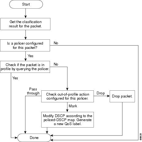
After a packet is classified and has a DSCP-based or CoS-based QoS label assigned to it, the policing and marking process can begin as shown in Figure 24-4.
Policing involves creating a policer that specifies the bandwidth limits for the traffic. Packets that exceed the limits are out of profile or nonconforming. Each policer determines on a packet-by-packet basis whether the packet is in or out of profile and specifies the actions on the packet. These actions, carried out by the marker, include passing through the packet without modification, dropping the packet, or modifying (marking down) the assigned DSCP of the packet and allowing the packet to pass through. The configurable policed-DSCP map provides the packet with a new DSCP-based QoS label. For information on the policed-DSCP map, see the "Mapping Tables" section. Marked-down packets use the same queues as the original QoS label to prevent packets in a flow from getting out of order.
Note ![]() All traffic, regardless of whether it is bridged or routed, is subjected to a policer, if one is configured. As a result, bridged packets might be dropped or might have their DSCP or CoS fields modified when they are policed and marked.
All traffic, regardless of whether it is bridged or routed, is subjected to a policer, if one is configured. As a result, bridged packets might be dropped or might have their DSCP or CoS fields modified when they are policed and marked.
You can create these types of policers:
•![]() Individual
Individual
QoS applies the bandwidth limits specified in the policer separately to each matched traffic class. You configure this type of policer within a policy map by using the police policy-map class configuration command.
•![]() Aggregate
Aggregate
QoS applies the bandwidth limits specified in an aggregate policer cumulatively to all matched traffic flows. You configure this type of policer by specifying the aggregate policer name within a policy map by using the police aggregate policy-map class configuration command. You specify the bandwidth limits of the policer by using the mls qos aggregate-policer global configuration command. In this way, the aggregate policer is shared by multiple classes of traffic within a policy map.
Policing uses a token-bucket algorithm. As each frame is received by the switch, a token is added to the bucket. The bucket has a hole in it and leaks at a rate that you specify as the average traffic rate in bits per second. Each time a token is added to the bucket, the switch performs a check to determine if there is enough room in the bucket. If there is not enough room, the packet is marked as nonconforming, and the specified policer action is taken (dropped or marked down).
How quickly the bucket fills is a function of the bucket depth (burst-byte), the rate at which the tokens are removed (rate-bps), and the duration of the burst above the average rate. The size of the bucket imposes an upper limit on the burst length and determines the number of frames that can be transmitted back-to-back. If the burst is short, the bucket does not overflow, and no action is taken against the traffic flow. However, if a burst is long and at a higher rate, the bucket overflows, and the policing actions are taken against the frames in that burst.
You configure the bucket depth (the maximum burst that is tolerated before the bucket overflows) by using the burst-byte option of the police policy-map class configuration command or the mls qos aggregate-policer global configuration command. You configure how fast (the average rate) that the tokens are removed from the bucket by using the rate-bps option of the police policy-map class configuration command or the mls qos aggregate-policer global configuration command.
After you configure the policy map and policing actions, attach the policy to an ingress interface by using the service-policy interface configuration command. For configuration information, see the "Classifying, Policing, and Marking Traffic by Using Policy Maps" section and the "Classifying, Policing, and Marking Traffic by Using Aggregate Policers" section.
Figure 24-4 Policing and Marking Flowchart
Mapping Tables
During QoS processing, the switch represents the priority of all traffic (including non-IP traffic) with an QoS label based on the DSCP or CoS value from the classification stage:
•![]() During classification, QoS uses configurable mapping tables to derive a corresponding DSCP or CoS value from a received CoS, DSCP, or IP precedence value. These maps include the CoS-to-DSCP map and the IP-precedence-to-DSCP map. You configure these maps by using the mls qos map cos-dscp and the mls qos map ip-prec-dscp global configuration commands.
During classification, QoS uses configurable mapping tables to derive a corresponding DSCP or CoS value from a received CoS, DSCP, or IP precedence value. These maps include the CoS-to-DSCP map and the IP-precedence-to-DSCP map. You configure these maps by using the mls qos map cos-dscp and the mls qos map ip-prec-dscp global configuration commands.
On an ingress interface configured in the DSCP-trusted state, if the DSCP values are different between the QoS domains, you can apply the configurable DSCP-to-DSCP-mutation map to the interface that is on the boundary between the two QoS domains. You configure this map by using the mls qos map dscp-mutation global configuration command.
•![]() During policing, QoS can assign another DSCP value to an IP or a non-IP packet (if the packet is out of profile and the policer specifies a marked-down value). This configurable map is called the policed-DSCP map. You configure this map by using the mls qos map policed-dscp global configuration command.
During policing, QoS can assign another DSCP value to an IP or a non-IP packet (if the packet is out of profile and the policer specifies a marked-down value). This configurable map is called the policed-DSCP map. You configure this map by using the mls qos map policed-dscp global configuration command.
•![]() Before the traffic reaches the scheduling stage, QoS stores the packet in an ingress and an egress queue according to the QoS label. The QoS label is based on the DSCP or the CoS value in the packet and selects the queue through the DSCP input and output queue threshold maps or through the CoS input and output queue threshold maps. You configure these maps by using the mls qos srr-queue {input | output} dscp-map and the mls qos srr-queue {input | output} cos-map global configuration commands.
Before the traffic reaches the scheduling stage, QoS stores the packet in an ingress and an egress queue according to the QoS label. The QoS label is based on the DSCP or the CoS value in the packet and selects the queue through the DSCP input and output queue threshold maps or through the CoS input and output queue threshold maps. You configure these maps by using the mls qos srr-queue {input | output} dscp-map and the mls qos srr-queue {input | output} cos-map global configuration commands.
The CoS-to-DSCP, DSCP-to-CoS, and the IP-precedence-to-DSCP maps have default values that might or might not be appropriate for your network.
The default DSCP-to-DSCP-mutation map and the default policed-DSCP map are null maps; they map an incoming DSCP value to the same DSCP value. The DSCP-to-DSCP-mutation map is the only map you apply to a specific port. All other maps apply to the entire switch.
For configuration information, see the "Configuring DSCP Maps" section.
For information about the DSCP and CoS input queue threshold maps, see the "Queueing and Scheduling on Ingress Queues" section. For information about the DSCP and CoS output queue threshold maps, see the "Queueing and Scheduling on Egress Queues" section.
Queueing and Scheduling Overview
The switch has queues at specific points to help prevent congestion as shown in Figure 24-5.
Figure 24-5 Ingress and Egress Queue Location

Because the total ingress bandwidth of all ports can exceed the bandwidth of the stack ring, ingress queues are located after the packet is classified, policed, and marked and before packets are forwarded into the switch fabric. Because multiple ingress ports can simultaneously send packets to an egress port and cause congestion, egress queues are located after the stack ring.
Weighted Tail Drop
Both the ingress and egress queues use an enhanced version of the tail-drop congestion-avoidance mechanism called weighted tail drop (WTD). WTD is implemented on queues to manage the queue lengths and to provide drop precedences for different traffic classifications.
As a frame is enqueued to a particular queue, WTD uses the frame's assigned QoS label to subject it to different thresholds. If the threshold is exceeded for that QoS label (the space available in the destination queue is less than the size of the frame), the switch drops the frame.
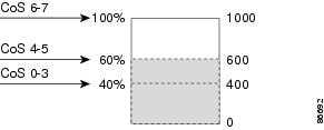
Figure 24-6 shows an example of WTD operating on a queue whose size is 1000 frames. Three drop percentages are configured: 40 percent (400 frames), 60 percent (600 frames), and 100 percent (1000 frames). These percentages mean that up to 400 frames can be queued at the 40-percent threshold, up to 600 frames at the 60-percent threshold, and up to 1000 frames at the 100-percent threshold.
In this example, CoS values 6 and 7 have a greater importance than the other CoS values, and they are assigned to the 100-percent drop threshold (queue-full state). CoS values 4 and 5 are assigned to the 60-percent threshold, and CoS values 0 to 3 are assigned to the 40-percent threshold.
Suppose the queue is already filled with 600 frames, and a new frame arrives. It contains CoS values 4 and 5 and is subjected to the 60-percent threshold. If this frame is added to the queue, the threshold will be exceeded, so the switch drops it.
Figure 24-6 WTD and Queue Operation
For more information, see the "Mapping DSCP or CoS Values to an Ingress Queue and Setting WTD Thresholds" section, the "Allocating Buffer Space to and Setting WTD Thresholds for an Egress Queue-Set" section, and the "Mapping DSCP or CoS Values to an Egress Queue and to a Threshold ID" section.
SRR Shaping and Sharing
Both the ingress and egress queues are serviced by SRR, which determines the rate at which packets are sent. On the ingress queues, SRR sends packets to the stack ring. On the egress queues, SRR sends packets to the egress interface.
You can configure SRR on egress queues for sharing or for shaping. However, for ingress queues, sharing is the default mode, and it is the only mode supported.
In shaped mode, the egress queues are guaranteed a percentage of the bandwidth, and they are rate-limited to that amount. Shaped traffic does not use more than the allocated bandwidth even if the link is idle. Shaping provides a more even flow of traffic over time and reduces the peaks and valleys of bursty traffic. With shaping, the absolute value of each weight is used to compute the bandwidth available for the queues.
In shared mode, the queues share the bandwidth among them according to the configured weights. The bandwidth is guaranteed at this level but not limited to it. For example, if a queue is empty and no longer requires a share of the link, the remaining queues can expand into the unused bandwidth and share it among them. With sharing, the ratio of the weights determines the frequency of dequeuing; the absolute values are meaningless.
For more information, see the "Allocating Bandwidth Between the Ingress Queues" section, the "Configuring SRR Shaped Weights on Egress Queues" section, and the "Configuring SRR Shared Weights on Egress Queues" section.
Queueing and Scheduling on Ingress Queues
Figure 24-7 shows the queueing and scheduling flowchart for ingress ports.
Figure 24-7 Queueing and Scheduling Flowchart for Ingress Ports

Note ![]() SRR services the priority queue for its configured share before servicing the other queue.
SRR services the priority queue for its configured share before servicing the other queue.
The switch supports two configurable ingress queues, which are serviced by SRR in shared mode only. Table 24-1 describes the queues.
|
|
|
|---|---|
Normal |
User traffic that is considered to be normal priority. You can configure three different thresholds to differentiate among the flows. You can use the mls qos srr-queue input threshold, the mls qos srr-queue input dscp-map, and the mls qos srr-queue input cos-map global configuration commands. |
Expedite |
High-priority user traffic such as differentiated services (DF) expedited forwarding or voice traffic. You can configure the bandwidth required for this traffic as a percentage of the total stack traffic by using the mls qos srr-queue input priority-queue global configuration command. The expedite queue has guaranteed bandwidth. |
1 The switch uses two nonconfigurable queues for traffic that is essential for proper network and stack operation. |
You assign each packet that flows through the switch to a queue and to a threshold. Specifically, you map DSCP or CoS values to an ingress queue and map DSCP or CoS values to a threshold ID. You use the mls qos srr-queue input dscp-map queue queue-id {dscp1...dscp8 | threshold threshold-id dscp1...dscp8} or the mls qos srr-queue input cos-map queue queue-id {cos1...cos8 | threshold threshold-id cos1...cos8} global configuration command. You can display the DSCP input queue threshold map and the CoS input queue threshold map by using the show mls qos maps privileged EXEC command.
WTD Thresholds
The queues use WTD to support distinct drop percentages for different traffic classes. Each queue has three drop thresholds: two configurable (explicit) WTD thresholds and one nonconfigurable (implicit) threshold preset to the queue-full state. You assign the two explicit WTD threshold percentages for threshold ID 1 and ID 2 to the ingress queues by using the mls qos srr-queue input threshold queue-id threshold-percentage1 threshold-percentage2 global configuration command. Each threshold value is a percentage of the total number of allocated buffers for the queue. The drop threshold for threshold ID 3 is preset to the queue-full state, and you cannot modify it. For more information about how WTD works, see the "Weighted Tail Drop" section.
Buffer and Bandwidth Allocation
You define the ratio (allocate the amount of space) with which to divide the ingress buffers between the two queues by using the mls qos srr-queue input buffers percentage1 percentage2 global configuration command. The buffer allocation together with the bandwidth allocation determine how much data can be buffered and sent before packets are dropped. You allocate bandwidth as a percentage by using the mls qos srr-queue input bandwidth weight1 weight2 global configuration command. The ratio of the weights is the ratio of the frequency in which the SRR scheduler sends packets from each queue.
Priority Queueing
You can configure one ingress queue as the priority queue by using the mls qos srr-queue input priority-queue queue-id bandwidth weight global configuration command. The priority queue should be used for traffic (such as voice) that requires guaranteed delivery because this queue is guaranteed part of the bandwidth regardless of the load on the stack ring.
SRR services the priority queue for its configured weight as specified by the bandwidth keyword in the mls qos srr-queue input priority-queue queue-id bandwidth weight global configuration command. Then, SRR shares the remaining bandwidth with both ingress queues and services them as specified by the weights configured with the mls qos srr-queue input bandwidth weight1 weight2 global configuration command.
You can combine the commands described in this section to prioritize traffic by placing packets with particular DSCPs or CoSs into certain queues, by allocating a large queue size or by servicing the queue more frequently, and by adjusting queue thresholds so that packets with lower priorities are dropped. For configuration information, see the "Configuring Ingress Queue Characteristics" section.
Queueing and Scheduling on Egress Queues
Figure 24-8 shows the queueing and scheduling flowchart for egress ports.
Figure 24-8 Queueing and Scheduling Flowchart for Egress Ports

Each port supports four egress queues. These queues are assigned to a queue-set. All traffic exiting the switch flows through one of these four queues and is subjected to a threshold based on the QoS label assigned to the packet.
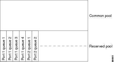
Figure 24-9 shows the egress queue buffer. The buffer space is divided between the common pool and the reserved pool. The switch uses a buffer allocation scheme to reserve a minimum amount of buffers for each egress queue, to prevent any queue or port from consuming all the buffers and depriving other queues, and to determine whether to grant buffer space to a requesting queue. The switch determines whether the target queue has not consumed more buffers than its reserved amount (under-limit), whether it has consumed all of its maximum buffers (over limit), and whether the common pool is empty (no free buffers) or not empty (free buffers). If the queue is not over-limit, the switch can allocate buffer space from the reserved pool or from the common pool (if it is not empty). If there are no free buffers in the common pool or if the queue is over-limit, the switch drops the frame.
Figure 24-9 Egress Queue Buffer Allocation
Buffer and Memory Allocation
You guarantee the availability of buffers, set drop thresholds, and configure the maximum memory allocation for a queue-set by using the mls qos queue-set output qset-id threshold queue-id drop-threshold1 drop-threshold2 reserved-threshold maximum-threshold global configuration command. Each threshold value is a percentage of the queue's allocated memory, which you specify by using the mls qos queue-set output qset-id buffers allocation1 ... allocation4 global configuration command. The sum of all the allocated buffers represents the reserved pool, and the remaining buffers are part of the common pool.
Through buffer allocation, you can ensure that high-priority traffic is buffered. For example, if the buffer space is 400, you can allocate 70 percent of it to queue 1 and 10 percent to queues 2 through 4. Queue 1 then has 280 buffers allocated to it, and queues 2 through 4 each have 40 buffers allocated to them.
You can guarantee that the allocated buffers are reserved for a specific queue in a queue-set. For example, if there are 100 buffers for a queue, you can reserve 50 percent (50 buffers). The switch returns the remaining 50 buffers to the common pool. You also can enable a queue in the full condition to obtain more buffers than are reserved for it by setting a maximum threshold. The switch can allocate the needed buffers from the common pool if the common pool is not empty.
WTD Thresholds
You can assign each packet that flows through the switch to a queue and to a threshold. Specifically, you map DSCP or CoS values to an egress queue and map DSCP or CoS values to a threshold ID. You use the mls qos srr-queue output dscp-map queue queue-id {dscp1...dscp8 | threshold threshold-id dscp1...dscp8} or the mls qos srr-queue output cos-map queue queue-id {cos1...cos8 | threshold threshold-id cos1...cos8} global configuration command. You can display the DSCP output queue threshold map and the CoS output queue threshold map by using the show mls qos maps privileged EXEC command.
The queues use WTD to support distinct drop percentages for different traffic classes. Each queue has three drop thresholds: two configurable (explicit) WTD thresholds and one nonconfigurable (implicit) threshold preset to the queue-full state. You assign the two WTD threshold percentages for threshold ID 1 and ID 2. The drop threshold for threshold ID 3 is preset to the queue-full state, and you cannot modify it. For more information about how WTD works, see the "Weighted Tail Drop" section.
Shaped or Shared Mode
SRR services each queue-set in shared or shaped mode.You map an interface to a queue-set by using the queue-set qset-id interface configuration command. You assign shared or shaped weights to the interface by using the srr-queue bandwidth share weight1 weight2 weight3 weight4 or the srr-queue bandwidth shape weight1 weight2 weight3 weight4 interface configuration command. For an explanation of the differences between shaping and sharing, see the "SRR Shaping and Sharing" section.
The buffer allocation together with the SRR weight ratios determine how much data can be buffered and sent before packets are dropped. The weight ratio is the ratio of the frequency in which the SRR scheduler sends packets from each queue.
You can combine the commands described in this section to prioritize traffic by placing packets with particular DSCPs or CoSs into certain queues, by allocating a large queue size or by servicing the queue more frequently, and by adjusting queue thresholds so that packets with lower priorities are dropped. For configuration information, see the "Configuring Egress Queue Characteristics" section.
Note ![]() The egress queue default settings are suitable for most situations. You should change them only when you have a thorough understanding of the egress queues and if these settings do not meet your QoS solution.
The egress queue default settings are suitable for most situations. You should change them only when you have a thorough understanding of the egress queues and if these settings do not meet your QoS solution.
Packet Modification
A packet is classified, policed, and queued to provide QoS. Packet modifications can occur during this process:
•![]() For IP and non-IP packets, classification involves assigning a QoS label to a packet based on the DSCP or CoS of the received packet. However, the packet is not modified at this stage; only an indication of the assigned DSCP or CoS value is carried along. The reason for this is that QoS classification and forwarding lookups occur in parallel, and it is possible that the packet is forwarded with its original DSCP to the CPU where it is again processed through software.
For IP and non-IP packets, classification involves assigning a QoS label to a packet based on the DSCP or CoS of the received packet. However, the packet is not modified at this stage; only an indication of the assigned DSCP or CoS value is carried along. The reason for this is that QoS classification and forwarding lookups occur in parallel, and it is possible that the packet is forwarded with its original DSCP to the CPU where it is again processed through software.
•![]() During policing, IP and non-IP packets can have another DSCP assigned to them (if they are out of profile and the policer specifies a markdown DSCP). Once again, the DSCP in the packet is not modified, but an indication of the marked-down value is carried along. For IP packets, the packet modification occurs at a later stage; for non-IP packets the DSCP is converted to CoS and used for queueing and scheduling decisions.
During policing, IP and non-IP packets can have another DSCP assigned to them (if they are out of profile and the policer specifies a markdown DSCP). Once again, the DSCP in the packet is not modified, but an indication of the marked-down value is carried along. For IP packets, the packet modification occurs at a later stage; for non-IP packets the DSCP is converted to CoS and used for queueing and scheduling decisions.
•![]() Depending on the QoS label assigned to a frame and the mutation chosen, the DSCP and CoS values of the frame are rewritten. If you do not configure the mutation map and if you configure the interface to trust the DSCP of the incoming frame, the DSCP value in the frame is not changed, but the CoS is rewritten according to the DSCP-to-CoS map. If you configure the interface to trust the CoS of the incoming frame and it is an IP packet, the CoS value in the frame is not changed, but the DSCP might be changed according to the CoS-to-DSCP map.
Depending on the QoS label assigned to a frame and the mutation chosen, the DSCP and CoS values of the frame are rewritten. If you do not configure the mutation map and if you configure the interface to trust the DSCP of the incoming frame, the DSCP value in the frame is not changed, but the CoS is rewritten according to the DSCP-to-CoS map. If you configure the interface to trust the CoS of the incoming frame and it is an IP packet, the CoS value in the frame is not changed, but the DSCP might be changed according to the CoS-to-DSCP map.
The input mutation causes the DSCP to be rewritten depending on the new value of DSCP chosen. The set action in a policy map also causes the DSCP to be rewritten.
Configuring QoS
Before configuring QoS, you must have a thorough understanding of these items:
•![]() The types of applications used and the traffic patterns on your network.
The types of applications used and the traffic patterns on your network.
•![]() Traffic characteristics and needs of your network. Is the traffic bursty? Do you need to reserve bandwidth for voice and video streams?
Traffic characteristics and needs of your network. Is the traffic bursty? Do you need to reserve bandwidth for voice and video streams?
•![]() Bandwidth requirements and speed of the network.
Bandwidth requirements and speed of the network.
•![]() Location of congestion points in the network.
Location of congestion points in the network.
These sections describe how to configure QoS on your switch:
•![]() Enabling QoS Globally (required)
Enabling QoS Globally (required)
•![]() Configuring Classification Using Port Trust States (required
Configuring Classification Using Port Trust States (required
•![]() Configuring a QoS Policy (required)
Configuring a QoS Policy (required)
•![]() Configuring DSCP Maps (optional, unless you need to use the DSCP-to-DSCP-mutation map or the policed-DSCP map)
Configuring DSCP Maps (optional, unless you need to use the DSCP-to-DSCP-mutation map or the policed-DSCP map)
•![]() Configuring Ingress Queue Characteristics (optional)
Configuring Ingress Queue Characteristics (optional)
•![]() Configuring Egress Queue Characteristics (optional)
Configuring Egress Queue Characteristics (optional)
Default QoS Configuration
QoS is disabled. There is no concept of trusted or untrusted ports because the packets are not modified (the CoS, DSCP, and IP precedence values in the packet are not changed). Traffic is switched in pass-through mode (packets are switched without any rewrites and classified as best effort without any policing).
When QoS is enabled with the mls qos global configuration command and all other QoS settings are at their defaults, traffic is classified as best effort (the DSCP and CoS value is set to 0) without any policing. No policy maps are configured. The default port trust state on all ports is untrusted. The default ingress and egress queue settings are described in the "Default Ingress Queue Configuration" section and the "Default Egress Queue Configuration" section.
Default Ingress Queue Configuration
Table 24-2 shows the default ingress queue configuration when QoS is enabled.
|
|
|
|
|---|---|---|
Buffer Allocation |
90 percent |
10 percent |
Bandwidth Allocation 1 |
4 |
4 |
Priority Queue Bandwidth 2 |
0 |
10 |
WTD Drop Threshold 1 |
100 percent |
100 percent |
WTD Drop Threshold 2 |
100 percent |
100 percent |
1 The bandwidth is equally shared between the queues. SRR sends packets in shared mode only. 2 Queue 2 is the priority queue. SRR services the priority queue for its configured share before servicing the other queue. |
Table 24-3 shows the default CoS input queue threshold map when QoS is enabled.
CoS Value |
0-4 |
5 |
6, 7 |
Queue ID - Threshold ID |
1 - 1 |
2 - 1 |
1 - 1 |
Table 24-4 shows the default DSCP input queue threshold map when QoS is enabled.
DSCP Value |
0-39 |
40-47 |
48-63 |
Queue ID - Threshold ID |
1 - 1 |
2 - 1 |
1 - 1 |
Default Egress Queue Configuration
Table 24-5 shows the default egress queue configuration for each queue-set when QoS is enabled. All ports are mapped to queue-set 1. The port bandwidth limit is set to 100 percent and rate unlimited.
|
|
|
|
|
|
|---|---|---|---|---|
Buffer Allocation |
25 percent |
25 percent |
25 percent |
25 percent |
WTD Drop Threshold 1 |
100 percent |
50 percent |
100 percent |
100 percent |
WTD Drop Threshold 2 |
100 percent |
50 percent |
100 percent |
100 percent |
Reserved Threshold |
50 percent |
100 percent |
50 percent |
50 percent |
Maximum Threshold |
400 percent |
400 percent |
400 percent |
400 percent |
SRR Shaped Weights (absolute) 1 |
25 |
0 |
0 |
0 |
SRR Shared Weights 2 |
25 |
25 |
25 |
25 |
1 A shaped weight of zero means that this queue is operating in shared mode. 2 One quarter of the bandwidth is allocated to each queue. |
Table 24-6 shows the default CoS output queue threshold map when QoS is enabled.
CoS Value |
0, 1 |
2, 3 |
4 |
5 |
6, 7 |
Queue ID - Threshold ID |
2 - 1 |
3 - 1 |
4 - 1 |
1 -1 |
4 - 1 |
Table 24-7 shows the default DSCP output queue threshold map when QoS is enabled.
DSCP Value |
0-15 |
16-31 |
32-39 |
40-47 |
48-63 |
Queue ID - Threshold ID |
2 - 1 |
3 - 1 |
4 - 1 |
1 - 1 |
4 - 1 |
Default Mapping Table Configuration
The default CoS-to-DSCP map is shown in Table 24-8.
The default IP-precedence-to-DSCP map is shown in Table 24-9.
The default DSCP-to-CoS map is shown in Table 24-10.
The default DSCP-to-DSCP-mutation map is a null map, which maps an incoming DSCP value to the same DSCP value.
The default policed-DSCP map is a null map, which maps an incoming DSCP value to the same DSCP value (no markdown).
QoS Configuration Guidelines
Before beginning the QoS configuration, you should be aware of this information:
•![]() You configure QoS only on physical ports; there is no support for it on the VLAN or switch virtual interface level.
You configure QoS only on physical ports; there is no support for it on the VLAN or switch virtual interface level.
•![]() It is not possible to match IP fragments against configured IP extended ACLs to enforce QoS. IP fragments are sent as best-effort. IP fragments are denoted by fields in the IP header.
It is not possible to match IP fragments against configured IP extended ACLs to enforce QoS. IP fragments are sent as best-effort. IP fragments are denoted by fields in the IP header.
•![]() Only one ACL per class map and only one match class-map configuration command per class map are supported. The ACL can have multiple ACEs, which match fields against the contents of the packet.
Only one ACL per class map and only one match class-map configuration command per class map are supported. The ACL can have multiple ACEs, which match fields against the contents of the packet.
•![]() Incoming traffic is classified, policed, and marked down (if configured) regardless of whether the traffic is bridged, routed, or sent to the CPU. It is possible for bridged frames to be dropped or to have their DSCP and CoS values modified.
Incoming traffic is classified, policed, and marked down (if configured) regardless of whether the traffic is bridged, routed, or sent to the CPU. It is possible for bridged frames to be dropped or to have their DSCP and CoS values modified.
•![]() Only one policer is applied to a packet on an ingress interface. Only the average rate and committed burst parameters are configurable.
Only one policer is applied to a packet on an ingress interface. Only the average rate and committed burst parameters are configurable.
•![]() The port ASIC supports 256 policers (255 policers plus 1 no policer). The maximum number of policers supported per port is 64. For example, you could configure 32 policers on a Gigabit Ethernet port and 8 policers on a Fast Ethernet port, or you could configure 64 policers on a Gigabit Ethernet port and 5 policers on a Fast Ethernet port. Policers are allocated on demand by the software and are constrained by the hardware and ASIC boundaries. You cannot reserve policers per port; there is no guarantee that a port will be assigned to any policer.
The port ASIC supports 256 policers (255 policers plus 1 no policer). The maximum number of policers supported per port is 64. For example, you could configure 32 policers on a Gigabit Ethernet port and 8 policers on a Fast Ethernet port, or you could configure 64 policers on a Gigabit Ethernet port and 5 policers on a Fast Ethernet port. Policers are allocated on demand by the software and are constrained by the hardware and ASIC boundaries. You cannot reserve policers per port; there is no guarantee that a port will be assigned to any policer.
•![]() On an interface configured for QoS, all traffic received through the interface is classified, policed, and marked according to the policy map attached to the interface. On a trunk interface configured for QoS, traffic in all VLANs received through the interface is classified, policed, and marked according to the policy map attached to the interface.
On an interface configured for QoS, all traffic received through the interface is classified, policed, and marked according to the policy map attached to the interface. On a trunk interface configured for QoS, traffic in all VLANs received through the interface is classified, policed, and marked according to the policy map attached to the interface.
•![]() You can create an aggregate policer that is shared by multiple traffic classes within the same policy map. However, you cannot use the aggregate policer across different policy maps.
You can create an aggregate policer that is shared by multiple traffic classes within the same policy map. However, you cannot use the aggregate policer across different policy maps.
•![]() If you have EtherChannel ports configured on your switch, you must configure QoS classification, policing, mapping, and queueing on the individual physical ports that comprise the EtherChannel. You must decide whether the QoS configuration should match on all ports in the EtherChannel.
If you have EtherChannel ports configured on your switch, you must configure QoS classification, policing, mapping, and queueing on the individual physical ports that comprise the EtherChannel. You must decide whether the QoS configuration should match on all ports in the EtherChannel.
•![]() Control traffic (such as spanning-tree bridge protocol data units [BPDUs] and routing update packets) received by the switch are subject to all ingress QoS processing.
Control traffic (such as spanning-tree bridge protocol data units [BPDUs] and routing update packets) received by the switch are subject to all ingress QoS processing.
•![]() You are likely to lose data when you change queue settings; therefore, try to make changes when traffic is at a minimum.
You are likely to lose data when you change queue settings; therefore, try to make changes when traffic is at a minimum.
Enabling QoS Globally
By default, QoS is disabled on the switch.
Beginning in privileged EXEC mode, follow these steps to enable QoS. This procedure is required.
|
|
|
|
|---|---|---|
Step 1 |
configure terminal |
Enter global configuration mode. |
Step 2 |
mls qos |
Enable QoS globally. QoS runs from the default settings described in the "Default QoS Configuration" section, the "Queueing and Scheduling on Ingress Queues" section, and the "Queueing and Scheduling on Egress Queues" section. |
Step 3 |
end |
Return to privileged EXEC mode. |
Step 4 |
show mls qos |
Verify your entries. |
Step 5 |
copy running-config startup-config |
(Optional) Save your entries in the configuration file. |
To disable QoS, use the no mls qos global configuration command.
Configuring Classification Using Port Trust States
These sections describe how to classify incoming traffic by using port trust states. Depending on your network configuration, you must perform one or more of these tasks or one or more of the tasks in the "Configuring a QoS Policy" section:
•![]() Configuring the Trust State on Ports within the QoS Domain
Configuring the Trust State on Ports within the QoS Domain
•![]() Configuring the CoS Value for an Interface
Configuring the CoS Value for an Interface
•![]() Configuring the DSCP Trust State on a Port Bordering Another QoS Domain
Configuring the DSCP Trust State on a Port Bordering Another QoS Domain
Configuring the Trust State on Ports within the QoS Domain
Packets entering a QoS domain are classified at the edge of the QoS domain. When the packets are classified at the edge, the switch port within the QoS domain can be configured to one of the trusted states because there is no need to classify the packets at every switch within the QoS domain. Figure 24-10 shows a sample network topology.
Figure 24-10 Port Trusted States within the QoS Domain

Beginning in privileged EXEC mode, follow these steps to configure the port to trust the classification of the traffic that it receives:
To return a port to its untrusted state, use the no mls qos trust interface configuration command.
For information on how to change the default CoS value, see the "Configuring the CoS Value for an Interface" section. For information on how to configure the CoS-to-DSCP map, see the "Configuring the CoS-to-DSCP Map" section.
Configuring the CoS Value for an Interface
QoS assigns the CoS value specified with the mls qos cos interface configuration command to untagged frames received on trusted and untrusted ports.
Beginning in privileged EXEC mode, follow these steps to define the default CoS value of a port or to assign the default CoS to all incoming packets on the port:
To return to the default setting, use the no mls qos cos {default-cos | override} interface configuration command.
Configuring the DSCP Trust State on a Port Bordering Another QoS Domain
If you are administering two separate QoS domains between which you want to implement QoS features for IP traffic, you can configure the switch ports bordering the domains to a DSCP-trusted state as shown in Figure 24-11. Then the receiving port accepts the DSCP-trusted value and avoids the classification stage of QoS. If the two domains use different DSCP values, you can configure the DSCP-to-DSCP-mutation map to translate a set of DSCP values to match the definition in the other domain.
Figure 24-11 DSCP-Trusted State on a Port Bordering Another QoS Domain

Beginning in privileged EXEC mode, follow these steps to configure the DSCP-trusted state on a port and modify the DSCP-to-DSCP-mutation map. To ensure a consistent mapping strategy across both QoS domains, you must perform this procedure on the ports in both domains:
To return a port to its non-trusted state, use the no mls qos trust interface configuration command. To return to the default DSCP-to-DSCP-mutation map values, use the no mls qos map dscp-mutation dscp-mutation-name global configuration command.
This example shows how to configure Gigabit Ethernet port 0/3 on stack member 2 to the DSCP-trusted state and to modify the DSCP-to-DSCP-mutation map (named gi2/0/3-mutation) so that incoming DSCP values 10 to 13 are mapped to DSCP 30:
Switch(config)# mls qos map dscp-mutation gi2/0/3-mutation 10 11 12 13 to 30
Switch(config)# interface gigabitethernet2/0/3
Switch(config-if)# mls qos trust dscp
Switch(config-if)# mls qos dscp-mutation gi2/0/3-mutation
Switch(config-if)# end
Configuring a QoS Policy
Configuring a QoS policy typically requires classifying traffic into classes, configuring policies applied to those traffic classes, and attaching policies to interfaces.
For background information, see the "Classification" section and the "Policing and Marking" section. For configuration guidelines, see the "QoS Configuration Guidelines" section.
These sections describe how to classify, police, and mark traffic. Depending on your network configuration, you must perform one or more of these tasks:
•![]() Classifying Traffic by Using ACLs
Classifying Traffic by Using ACLs
•![]() Classifying Traffic by Using Class Maps
Classifying Traffic by Using Class Maps
•![]() Classifying, Policing, and Marking Traffic by Using Policy Maps
Classifying, Policing, and Marking Traffic by Using Policy Maps
•![]() Classifying, Policing, and Marking Traffic by Using Aggregate Policers
Classifying, Policing, and Marking Traffic by Using Aggregate Policers
Classifying Traffic by Using ACLs
You can classify IP traffic by using IP standard or IP extended ACLs; you can classify non-IP traffic by using Layer 2 MAC ACLs.
Beginning in privileged EXEC mode, follow these steps to create an IP standard ACL for IP traffic:
To delete an access list, use the no access-list access-list-number global configuration command.
This example shows how to allow access for only those hosts on the three specified networks. The wildcard bits apply to the host portions of the network addresses. Any host with a source address that does not match the access list statements is rejected.
Switch(config)# access-list 1 permit 192.5.255.0 0.0.0.255
Switch(config)# access-list 1 permit 128.88.0.0 0.0.255.255
Switch(config)# access-list 1 permit 36.0.0.0 0.0.0.255
! (Note: all other access implicitly denied)
Beginning in privileged EXEC mode, follow these steps to create an IP extended ACL for IP traffic:
To delete an access list, use the no access-list access-list-number global configuration command.
This example shows how to create an ACL that permits IP traffic from any source to any destination that has the DSCP value set to 32:
Switch(config)# access-list 100 permit ip any any dscp 32
This example shows how to create an ACL that permits IP traffic from a source host at 10.1.1.1 to a destination host at 10.1.1.2 with a precedence value of 5:
Switch(config)# access-list 100 permit ip host 10.1.1.1 host 10.1.1.2 precedence 5
This example shows how to create an ACL that permits PIM traffic from any source to a destination group address of 224.0.0.2 with a DSCP set to 32:
Switch(config)# access-list 102 permit pim any 224.0.0.2 dscp 32
Beginning in privileged EXEC mode, follow these steps to create a Layer 2 MAC ACL for non-IP traffic:
To delete an access list, use the no mac access-list extended access-list-name global configuration command.
This example shows how to create a Layer 2 MAC ACL with two permit statements. The first statement allows traffic from the host with MAC address 0001.0000.0001 to the host with MAC address 0002.0000.0001. The second statement allows only Ethertype XNS-IDP traffic from the host with MAC address 0001.0000.0002 to the host with MAC address 0002.0000.0002.
Switch(config)# mac access-list extended maclist1
Switch(config-ext-macl)# permit 0001.0000.0001 0.0.0 0002.0000.0001 0.0.0
Switch(config-ext-macl)# permit 0001.0000.0002 0.0.0 0002.0000.0002 0.0.0 xns-idp
! (Note: all other access implicitly denied)
Classifying Traffic by Using Class Maps
You use the class-map global configuration command to name and to isolate a specific traffic flow (or class) from all other traffic. The class map defines the criteria to use to match against a specific traffic flow to further classify it. Match statements can include criteria such as an ACL, IP precedence values, or DSCP values. The match criterion is defined with one match statement entered within the class-map configuration mode.
Note ![]() You can also create class-maps during policy map creation by using the class policy-map configuration command. For more information, see the "Classifying, Policing, and Marking Traffic by Using Policy Maps" section.
You can also create class-maps during policy map creation by using the class policy-map configuration command. For more information, see the "Classifying, Policing, and Marking Traffic by Using Policy Maps" section.
Beginning in privileged EXEC mode, follow these steps to create a class map and to define the match criterion to classify traffic:
|
|
|
|
|---|---|---|
Step 1 |
configure terminal |
Enter global configuration mode. |
Step 2 |
access-list access-list-number {deny | permit} source [source-wildcard] or access-list access-list-number {deny | permit} protocol source [source-wildcard] destination [destination-wildcard] or mac access-list extended name {permit | deny} {host src-MAC-addr mask | any | host dst-MAC-addr | dst-MAC-addr mask} [type mask] |
Create an IP standard or extended ACL for IP traffic or a Layer 2 MAC ACL for non-IP traffic, repeating the command as many times as necessary. For more information, see the "Classifying Traffic by Using ACLs" section. Note |
Step 3 |
class-map [match-all | match-any] class-map-name |
Create a class map, and enter class-map configuration mode. By default, no class maps are defined. • • • If neither the match-all or match-any keyword is specified, the default is match-all. Note |
Step 4 |
match {access-group acl-index-or-name | ip dscp dscp-list | ip precedence ip-precedence-list} |
Define the match criterion to classify traffic. By default, no match criterion is defined. Only one match criterion per class map is supported, and only one ACL per class map is supported. • • • |
Step 5 |
end |
Return to privileged EXEC mode. |
Step 6 |
show class-map |
Verify your entries. |
Step 7 |
copy running-config startup-config |
(Optional) Save your entries in the configuration file. |
To delete an existing class map, use the no class-map [match-all | match-any] class-map-name global configuration command. To remove a match criterion, use the no match {access-group acl-index-or-name | ip dscp | ip precedence} class-map configuration command.
This example shows how to configure the class map called class1. The class1 has one match criterion, which is access list 103. It permits traffic from any host to any destination that matches a DSCP value of 10.
Switch(config)# access-list 103 permit any any dscp 10
Switch(config)# class-map class1
Switch(config-cmap)# match access-group 103
Switch(config-cmap)# end
Switch#
This example shows how to create a class map called class2, which matches incoming traffic with DSCP values of 10, 11, and 12.
Switch(config)# class-map class2
Switch(config-cmap)# match ip dscp 10 11 12
Switch(config-cmap)# end
Switch#
This example shows how to create a class map called class3, which matches incoming traffic with IP-precedence values of 5, 6, and 7:
Switch(config)# class-map class3
Switch(config-cmap)# match ip precedence 5 6 7
Switch(config-cmap)# end
Switch#
Classifying, Policing, and Marking Traffic by Using Policy Maps
A policy map specifies which traffic class to act on. Actions can include trusting the CoS, DSCP, or IP precedence values in the traffic class; setting a specific DSCP or IP precedence value in the traffic class; and specifying the traffic bandwidth limitations for each matched traffic class (policer) and the action to take when the traffic is out of profile (marking).
A policy map also has these characteristics:
•![]() A policy map can contain multiple class statements, each with different match criteria and policers.
A policy map can contain multiple class statements, each with different match criteria and policers.
•![]() A separate policy-map class can exist for each type of traffic received through an interface.
A separate policy-map class can exist for each type of traffic received through an interface.
•![]() A policy-map trust state and an interface trust state are mutually exclusive, and whichever is configured last takes affect.
A policy-map trust state and an interface trust state are mutually exclusive, and whichever is configured last takes affect.
You can attach only one policy map per ingress interface.
Beginning in privileged EXEC mode, follow these steps to create a policy map:
|
|
|
|
|---|---|---|
Step 1 |
configure terminal |
Enter global configuration mode. |
Step 2 |
class-map [match-all | match-any] class-map-name |
Create a class map, and enter class-map configuration mode. By default, no class maps are defined. • • • If neither the match-all or match-any keyword is specified, the default is match-all. Note |
Step 3 |
policy-map policy-map-name |
Create a policy map by entering the policy map name, and enter policy-map configuration mode. By default, no policy maps are defined. The default behavior of a policy map is to set the DSCP to 0 if the packet is an IP packet and to set the CoS to 0 if the packet is tagged. No policing is performed. |
Step 4 |
class class-map-name |
Define a traffic classification, and enter policy-map class configuration mode. By default, no policy map class-maps are defined. If a traffic class has already been defined by using the class-map global configuration command, specify its name for class-map-name in this command. |
Step 5 |
trust [cos | dscp | ip-precedence] |
Configure the trust state, which QoS uses to generate a CoS-based or DSCP-based QoS label. Note By default, the port is not trusted. If no keyword is specified when the command is entered, the default is dscp. The keywords have these meanings: • • • For more information, see the "Configuring the CoS-to-DSCP Map" section. |
Step 6 |
set {ip dscp new-dscp | ip precedence new-precedence} |
Classify IP traffic by setting a new value in the packet. • • |
Step 7 |
police rate-bps burst-byte [exceed-action {drop | policed-dscp-transmit}] |
Define a policer for the classified traffic. By default, no policer is defined. For information on the number of policers supported, see the "QoS Configuration Guidelines" section. • • • |
Step 8 |
exit |
Return to policy map configuration mode. |
Step 9 |
exit |
Return to global configuration mode. |
Step 10 |
interface interface-id |
Enter interface configuration mode, and specify the interface to attach to the policy map. Valid interfaces include physical interfaces. |
Step 11 |
service-policy input policy-map-name |
Specify the policy-map name, and apply it to an ingress interface. Only one policy map per ingress interface is supported. |
Step 12 |
end |
Return to privileged EXEC mode. |
Step 13 |
show policy-map [policy-map-name [class class-map-name]] |
Verify your entries. |
Step 14 |
copy running-config startup-config |
(Optional) Save your entries in the configuration file. |
To delete an existing policy map, use the no policy-map policy-map-name global configuration command. To delete an existing class map, use the no class class-map-name policy-map configuration command. To return to the untrusted state, use the no trust policy-map configuration command. To remove an assigned DSCP or IP precedence value, use the no set {ip dscp new-dscp | ip precedence new-precedence} policy-map configuration command. To remove an existing policer, use the no police rate-bps burst-byte [exceed-action {drop | policed-dscp-transmit}] policy-map configuration command. To remove the policy map and interface association, use the no service-policy input policy-map-name interface configuration command.
This example shows how to create a policy map and attach it to an ingress interface on stack member 2. In the configuration, the IP standard ACL permits traffic from network 10.1.0.0. For traffic matching this classification, the DSCP value in the incoming packet is trusted. If the matched traffic exceeds an average traffic rate of 48000 bps and a normal burst size of 8000 bytes, its DSCP is marked down (based on the policed-DSCP map) and sent:
Switch(config)# access-list 1 permit 10.1.0.0 0.0.255.255
Switch(config)# class-map ipclass1
Switch(config-cmap)# match access-group 1
Switch(config-cmap)# exit
Switch(config)# policy-map flow1t
Switch(config-pmap)# class ipclass1
Switch(config-pmap-c)# trust dscp
Switch(config-pmap-c)# police 48000 8000 exceed-action policed-dscp-transmit
Switch(config-pmap-c)# exit
Switch(config-pmap)# exit
Switch(config)# interface gigabitethernet2/0/1
Switch(config-if)# service-policy input flow1t
This example shows how to create a Layer 2 MAC ACL with two permit statements and attach it to an ingress interface on the stack master. The first permit statement allows traffic from the host with MAC address 0001.0000.0001 destined for the host with MAC address 0002.0000.0001. The second permit statement allows only Ethertype XNS-IDP traffic from the host with MAC address 0001.0000.0002 destined for the host with MAC address 0002.0000.0002.
Switch(config)# mac access-list extended maclist1
Switch(config-ext-mac)# permit 0001.0000.0001 0.0.0 0002.0000.0001 0.0.0
Switch(config-ext-mac)# permit 0001.0000.0002 0.0.0 0002.0000.0002 0.0.0 xns-idp
Switch(config-ext-mac)# exit
Switch(config)# mac access-list extended maclist2
Switch(config-ext-mac)# permit 0001.0000.0003 0.0.0 0002.0000.0003 0.0.0
Switch(config-ext-mac)# permit 0001.0000.0004 0.0.0 0002.0000.0004 0.0.0 aarp
Switch(config-ext-mac)# exit
Switch(config)# class-map macclass1
Switch(config-cmap)# match access-group maclist1
Switch(config-cmap)# exit
Switch(config)# policy-map macpolicy1
Switch(config-pmap)# class macclass1
Switch(config-pmap-c)# set ip dscp 63
Switch(config-pmap-c)# exit
Switch(config-pmap)# class macclass2 maclist2
Switch(config-pmap-c)# set ip dscp 45
Switch(config-pmap-c)# exit
Switch(config-pmap)# exit
Switch(config)# interface gigabitethernet1/0/1
Switch(config-if)# mls qos trust cos
Switch(config-if)# service-policy input macpolicy1
Classifying, Policing, and Marking Traffic by Using Aggregate Policers
By using an aggregate policer, you can create a policer that is shared by multiple traffic classes within the same policy map. However, you cannot use the aggregate policer across different policy maps or interfaces.
Beginning in privileged EXEC mode, follow these steps to create an aggregate policer:
|
|
|
|
|---|---|---|
Step 1 |
configure terminal |
Enter global configuration mode. |
Step 2 |
mls qos aggregate-policer aggregate-policer-name rate-bps burst-byte exceed-action {drop | policed-dscp-transmit} |
Define the policer parameters that can be applied to multiple traffic classes within the same policy map. By default, no aggregate policer is defined. For information on the number of policers supported, see the "QoS Configuration Guidelines" section • • • • |
Step 3 |
class-map [match-all | match-any] class-map-name |
Create a class map to classify traffic as necessary. For more information, see the "Classifying Traffic by Using Class Maps" section. |
Step 4 |
policy-map policy-map-name |
Create a policy map by entering the policy map name, and enter policy-map configuration mode. For more information, see the "Classifying, Policing, and Marking Traffic by Using Policy Maps" section. |
Step 5 |
class class-map-name |
Define a traffic classification, and enter policy-map class configuration mode. For more information, see the "Classifying, Policing, and Marking Traffic by Using Policy Maps" section. |
Step 6 |
police aggregate aggregate-policer-name |
Apply an aggregate policer to multiple classes in the same policy map. For aggregate-policer-name, enter the name specified in Step 2. |
Step 7 |
exit |
Return to global configuration mode. |
Step 8 |
interface interface-id |
Enter interface configuration mode, and specify the interface to attach to the policy map. Valid interfaces include physical interfaces. |
Step 9 |
service-policy input policy-map-name |
Specify the policy-map name, and apply it to an ingress interface. Only one policy map per ingress interface is supported. |
Step 10 |
end |
Return to privileged EXEC mode. |
Step 11 |
show mls qos aggregate-policer [aggregate-policer-name] |
Verify your entries. |
Step 12 |
copy running-config startup-config |
(Optional) Save your entries in the configuration file. |
To remove the specified aggregate policer from a policy map, use the no police aggregate aggregate-policer-name policy map configuration mode. To delete an aggregate policer and its parameters, use the no mls qos aggregate-policer aggregate-policer-name global configuration command.
This example shows how to create an aggregate policer and attach it to multiple classes within a policy map. In the configuration, the IP ACLs permit traffic from network 10.1.0.0 and from host 11.3.1.1. For traffic coming from network 10.1.0.0, the DSCP in the incoming packets is trusted. For traffic coming from host 11.3.1.1, the DSCP in the packet is changed to 56. The traffic rate from the 10.1.0.0 network and from host 11.3.1.1 is policed. If the traffic exceeds an average rate of 48000 bps and a normal burst size of 8000 bytes, its DSCP is marked down (based on the policed-DSCP map) and sent. The policy map is attached to an ingress interface on stack member 2.
Switch(config)# access-list 1 permit 10.1.0.0 0.0.255.255
Switch(config)# access-list 2 permit 11.3.1.1
Switch(config)# mls qos aggregate-police transmit1 48000 8000 exceed-action
policed-dscp-transmit
Switch(config)# class-map ipclass1
Switch(config-cmap)# match access-group 1
Switch(config-cmap)# exit
Switch(config)# class-map ipclass2
Switch(config-cmap)# match access-group 2
Switch(config-cmap)# exit
Switch(config)# policy-map aggflow1
Switch(config-pmap)# class ipclass1
Switch(config-pmap-c)# trust dscp
Switch(config-pmap-c)# police aggregate transmit1
Switch(config-pmap-c)# exit
Switch(config-pmap)# class ipclass2
Switch(config-pmap-c)# set ip dscp 56
Switch(config-pmap-c)# police aggregate transmit1
Switch(config-pmap-c)# exit
Switch(config-pmap)# exit
Switch(config)# interface gigabitethernet2/0/1
Switch(config-if)# service-policy input aggflow1
Switch(config-if)# exit
Configuring DSCP Maps
These sections describe how to configure the DSCP maps:
•![]() Configuring the CoS-to-DSCP Map (optional)
Configuring the CoS-to-DSCP Map (optional)
•![]() Configuring the IP-Precedence-to-DSCP Map (optional)
Configuring the IP-Precedence-to-DSCP Map (optional)
•![]() Configuring the Policed-DSCP Map (optional, unless the null settings in the map are not appropriate)
Configuring the Policed-DSCP Map (optional, unless the null settings in the map are not appropriate)
•![]() Configuring the DSCP-to-CoS Map (optional)
Configuring the DSCP-to-CoS Map (optional)
•![]() Configuring the DSCP-to-DSCP-Mutation Map (optional, unless the null settings in the map are not appropriate)
Configuring the DSCP-to-DSCP-Mutation Map (optional, unless the null settings in the map are not appropriate)
All the maps, except the DSCP-to-DSCP-mutation map, are globally defined and are applied to all ports.
Configuring the CoS-to-DSCP Map
You use the CoS-to-DSCP map to map CoS values in incoming packets to a DSCP value that QoS uses internally to represent the priority of the traffic.
Table 24-8 shows the default CoS-to-DSCP map.
CoS value |
0 |
1 |
2 |
3 |
4 |
5 |
6 |
7 |
DSCP value |
0 |
8 |
16 |
24 |
32 |
40 |
48 |
56 |
If these values are not appropriate for your network, you need to modify them.
Beginning in privileged EXEC mode, follow these steps to modify the CoS-to-DSCP map. This procedure is optional.
To return to the default map, use the no mls qos cos-dscp global configuration command.
This example shows how to modify and display the CoS-to-DSCP map:
Switch(config)# mls qos map cos-dscp 10 15 20 25 30 35 40 45
Switch(config)# end
Switch# show mls qos maps cos-dscp
Cos-dscp map:
cos: 0 1 2 3 4 5 6 7
--------------------------------
dscp: 10 15 20 25 30 35 40 45
Configuring the IP-Precedence-to-DSCP Map
You use the IP-precedence-to-DSCP map to map IP precedence values in incoming packets to a DSCP value that QoS uses internally to represent the priority of the traffic.
Table 24-9 shows the default IP-precedence-to-DSCP map:
IP precedence value |
0 |
1 |
2 |
3 |
4 |
5 |
6 |
7 |
DSCP value |
0 |
8 |
16 |
24 |
32 |
40 |
48 |
56 |
If these values are not appropriate for your network, you need to modify them.
Beginning in privileged EXEC mode, follow these steps to modify the IP-precedence-to-DSCP map. This procedure is optional.
To return to the default map, use the no mls qos ip-prec-dscp global configuration command.
This example shows how to modify and display the IP-precedence-to-DSCP map:
Switch(config)# mls qos map ip-prec-dscp 10 15 20 25 30 35 40 45
Switch(config)# end
Switch# show mls qos maps ip-prec-dscp
IpPrecedence-dscp map:
ipprec: 0 1 2 3 4 5 6 7
--------------------------------
dscp: 10 15 20 25 30 35 40 45
Configuring the Policed-DSCP Map
You use the policed-DSCP map to mark down a DSCP value to a new value as the result of a policing and marking action.
The default policed-DSCP map is a null map, which maps an incoming DSCP value to the same DSCP value.
Beginning in privileged EXEC mode, follow these steps to modify the policed-DSCP map. This procedure is optional.
To return to the default map, use the no mls qos policed-dscp global configuration command.
This example shows how to map DSCP 50 to 57 to a marked-down DSCP value of 0:
Switch(config)# mls qos map policed-dscp 50 51 52 53 54 55 56 57 to 0
Switch(config)# end
Switch# show mls qos maps policed-dscp
Policed-dscp map:
d1 : d2 0 1 2 3 4 5 6 7 8 9
---------------------------------------
0 : 00 01 02 03 04 05 06 07 08 09
1 : 10 11 12 13 14 15 16 17 18 19
2 : 20 21 22 23 24 25 26 27 28 29
3 : 30 31 32 33 34 35 36 37 38 39
4 : 40 41 42 43 44 45 46 47 48 49
5 : 00 00 00 00 00 00 00 00 58 59
6 : 60 61 62 63
Note ![]() In this policed-DSCP map, the marked-down DSCP values are shown in the body of the matrix. The d1 column specifies the most-significant digit of the original DSCP; the d2 row specifies the least-significant digit of the original DSCP. The intersection of the d1 and d2 values provides the marked-down value. For example, an original DSCP value of 53 corresponds to a marked-down DSCP value of 0.
In this policed-DSCP map, the marked-down DSCP values are shown in the body of the matrix. The d1 column specifies the most-significant digit of the original DSCP; the d2 row specifies the least-significant digit of the original DSCP. The intersection of the d1 and d2 values provides the marked-down value. For example, an original DSCP value of 53 corresponds to a marked-down DSCP value of 0.
Configuring the DSCP-to-CoS Map
You use the DSCP-to-CoS map to generate a CoS value, which is used to select one of the four egress queues.
Table 24-10 shows the default DSCP-to-CoS map.
DSCP value |
0-7 |
8-15 |
16-23 |
24-31 |
32-39 |
40-47 |
48-55 |
56-63 |
CoS value |
0 |
1 |
2 |
3 |
4 |
5 |
6 |
7 |
If these values are not appropriate for your network, you need to modify them.
Beginning in privileged EXEC mode, follow these steps to modify the DSCP-to-CoS map. This procedure is optional.
To return to the default map, use the no mls qos dscp-cos global configuration command.
This example shows how to map DSCP values 0, 8, 16, 24, 32, 40, 48, and 50 to CoS value 0 and to display the map:
Switch(config)# mls qos map dscp-cos 0 8 16 24 32 40 48 50 to 0
Switch(config)# end
Switch# show mls qos maps dscp-cos
Dscp-cos map:
d1 : d2 0 1 2 3 4 5 6 7 8 9
---------------------------------------
0 : 00 00 00 00 00 00 00 00 00 01
1 : 01 01 01 01 01 01 00 02 02 02
2 : 02 02 02 02 00 03 03 03 03 03
3 : 03 03 00 04 04 04 04 04 04 04
4 : 00 05 05 05 05 05 05 05 00 06
5 : 00 06 06 06 06 06 07 07 07 07
6 : 07 07 07 07
Note ![]() In the above DSCP-to-CoS map, the CoS values are shown in the body of the matrix. The d1 column specifies the most-significant digit of the DSCP; the d2 row specifies the least-significant digit of the DSCP. The intersection of the d1 and d2 values provides the CoS value. For example, in the DSCP-to-CoS map, a DSCP value of 08 corresponds to a CoS value of 0.
In the above DSCP-to-CoS map, the CoS values are shown in the body of the matrix. The d1 column specifies the most-significant digit of the DSCP; the d2 row specifies the least-significant digit of the DSCP. The intersection of the d1 and d2 values provides the CoS value. For example, in the DSCP-to-CoS map, a DSCP value of 08 corresponds to a CoS value of 0.
Configuring the DSCP-to-DSCP-Mutation Map
If two QoS domains have different DSCP definitions, use the DSCP-to-DSCP-mutation map to translate one set of DSCP values to match the definition of another domain. You apply the DSCP-to-DSCP-mutation map to the receiving interface (ingress mutation) at the boundary of a QoS administrative domain.
With ingress mutation, the new DSCP value overwrites the one in the packet, and QoS treats the packet with this new value. The switch sends the packet out the interface with the new DSCP value.
You can configure multiple DSCP-to-DSCP-mutation maps on an ingress port. The default DSCP-to-DSCP-mutation map is a null map, which maps an incoming DSCP value to the same DSCP value.
Beginning in privileged EXEC mode, follow these steps to modify the DSCP-to-DSCP-mutation map. This procedure is optional.
To return to the default map, use the no mls qos dscp-mutation dscp-mutation-name global configuration command.
This example shows how to define the DSCP-to-DSCP-mutation map. All the entries that are not explicitly configured are not modified (remains as specified in the null map):
Switch(config)# mls qos map dscp-mutation mutation1 1 2 3 4 5 6 7 to 0
Switch(config)# mls qos map dscp-mutation mutation1 8 9 10 11 12 13 to 10
Switch(config)# mls qos map dscp-mutation mutation1 20 21 22 to 20
Switch(config)# mls qos map dscp-mutation mutation1 30 31 32 33 34 to 30
Switch(config)# interface gigabitethernet1/0/1
Switch(config-if)# mls qos trust dscp
Switch(config-if)# mls qos dscp-mutation mutation1
Switch(config-if)# end
Switch# show mls qos maps dscp-mutation mutation1
Dscp-dscp mutation map:
mutation1:
d1 : d2 0 1 2 3 4 5 6 7 8 9
---------------------------------------
0 : 00 00 00 00 00 00 00 00 10 10
1 : 10 10 10 10 14 15 16 17 18 19
2 : 20 20 20 23 24 25 26 27 28 29
3 : 30 30 30 30 30 35 36 37 38 39
4 : 40 41 42 43 44 45 46 47 48 49
5 : 50 51 52 53 54 55 56 57 58 59
6 : 60 61 62 63
Note ![]() In the above DSCP-to-DSCP-mutation map, the mutated values are shown in the body of the matrix. The d1 column specifies the most-significant digit of the original DSCP; the d2 row specifies the least-significant digit of the original DSCP. The intersection of the d1 and d2 values provides the mutated value. For example, a DSCP value of 12 corresponds to a mutated value of 10.
In the above DSCP-to-DSCP-mutation map, the mutated values are shown in the body of the matrix. The d1 column specifies the most-significant digit of the original DSCP; the d2 row specifies the least-significant digit of the original DSCP. The intersection of the d1 and d2 values provides the mutated value. For example, a DSCP value of 12 corresponds to a mutated value of 10.
Configuring Ingress Queue Characteristics
Depending on the complexity of your network and your QoS solution, you might need to perform all of the tasks in the next sections. You will need to make decisions about these characteristics:
•![]() Which packets are assigned (by DSCP or CoS value) to each queue?
Which packets are assigned (by DSCP or CoS value) to each queue?
•![]() What drop percentage thresholds apply to each queue, and which CoS or DSCP values map to each threshold?
What drop percentage thresholds apply to each queue, and which CoS or DSCP values map to each threshold?
•![]() How much of the available buffer space is allocated between the queues?
How much of the available buffer space is allocated between the queues?
•![]() How much of the available bandwidth is allocated between the queues?
How much of the available bandwidth is allocated between the queues?
•![]() Is there traffic (such as voice) that should be given high priority?
Is there traffic (such as voice) that should be given high priority?
These sections describe how to configure ingress queue characteristics:
•![]() Mapping DSCP or CoS Values to an Ingress Queue and Setting WTD Thresholds (optional)
Mapping DSCP or CoS Values to an Ingress Queue and Setting WTD Thresholds (optional)
•![]() Allocating Buffer Space Between the Ingress Queues (optional)
Allocating Buffer Space Between the Ingress Queues (optional)
•![]() Allocating Bandwidth Between the Ingress Queues (optional)
Allocating Bandwidth Between the Ingress Queues (optional)
•![]() Configuring the Ingress Priority Queue (optional)
Configuring the Ingress Priority Queue (optional)
Mapping DSCP or CoS Values to an Ingress Queue and Setting WTD Thresholds
You can prioritize traffic by placing packets with particular DSCPs or CoSs into certain queues and adjusting the queue thresholds so that packets with lower priorities are dropped.
Beginning in privileged EXEC mode, follow these steps to map DSCP or CoS values to an ingress queue and to set WTD thresholds. This procedure is optional.
To return to the default CoS input queue threshold map or the default DSCP input queue threshold map, use the no mls qos srr-queue input cos-map or the no mls qos srr-queue input dscp-map global configuration command. To return to the default WTD threshold percentages, use the no mls qos srr-queue input threshold queue-id global configuration command.
This example shows how to map DSCP values 0 to 6 to ingress queue 1 and to threshold 1 with a drop threshold of 50 percent. It maps DSCP values 20 to 26 to ingress queue 1 and to threshold 2 with a drop threshold of 70 percent:
Switch(config)# mls qos srr-queue input dscp-map queue 1 threshold 1 0 1 2 3 4 5 6
Switch(config)# mls qos srr-queue input dscp-map queue 1 threshold 2 20 21 22 23 24 25 26
Switch(config)# mls qos srr-queue input threshold 1 50 70
In this example, the DSCP values (0 to 6) are assigned the WTD threshold of 50 percent and will be dropped sooner than the DSCP values (20 to 26) assigned to the WTD threshold of 70 percent.
Allocating Buffer Space Between the Ingress Queues
You define the ratio (allocate the amount of space) with which to divide the ingress buffers between the two queues. The buffer and the bandwidth allocation determine how much data can be buffered before packets are dropped.
Beginning in privileged EXEC mode, follow these steps to allocate the buffers between the ingress queues. This procedure is optional.
To return to the default setting, use the no mls qos srr-queue input buffers global configuration command.
This example shows how to allocate 60 percent of the buffer space to ingress queue 1 and 40 percent of the buffer space to ingress queue 2:
Switch(config)# mls qos srr-queue input buffers 60 40
Allocating Bandwidth Between the Ingress Queues
You need to specify how much of the available bandwidth is allocated between the ingress queues. The ratio of the weights is the ratio of the frequency in which the SRR scheduler sends packets from each queue. The bandwidth and the buffer allocation determine how much data can be buffered before packets are dropped. On ingress queues, SRR operates only in shared mode.
Beginning in privileged EXEC mode, follow these steps to allocate bandwidth between the ingress queues. This procedure is optional.
|
|
|
|
|---|---|---|
Step 1 |
configure terminal |
Enter global configuration mode. |
Step 2 |
mls qos srr-queue input bandwidth weight1 weight2 |
Assign shared round robin weights to the ingress queues. The default setting for weight1 and weight2 is 4 (1/2 of the bandwidth is equally shared between the two queues). For weight1 and weight2, the range is 1 to 100. Separate each value with a space. SRR services the priority queue for its configured weight as specified by the bandwidth keyword in the mls qos srr-queue input priority-queue queue-id bandwidth weight global configuration command. Then, SRR shares the remaining bandwidth with both ingress queues and services them as specified by the weights configured with the mls qos srr-queue input bandwidth weight1 weight2 global configuration command. For more information, see the "Configuring the Ingress Priority Queue" section. |
Step 3 |
end |
Return to privileged EXEC mode. |
Step 4 |
show mls qos interface queueing or show mls qos input-queue |
Verify your entries. |
Step 5 |
copy running-config startup-config |
(Optional) Save your entries in the configuration file. |
To return to the default setting, use the no mls qos srr-queue input bandwidth global configuration command.
This example shows how to assign the ingress bandwidth for the queues in the stack. Priority queueing is disabled, and the shared bandwidth ratio allocated to queue 1 is 25/(25+75) and to queue 2 is 75/(25+75):
Switch(config)# mls qos srr-queue input priority-queue 2 bandwidth 0
Switch(config)# mls qos srr-queue input bandwidth 25 75
Configuring the Ingress Priority Queue
You should use the priority queue only for traffic that needs to be expedited (for example, voice traffic, which needs minimum delay and jitter).
The priority queue is guaranteed part of the bandwidth to reduce the delay and jitter under heavy network traffic on an oversubscribed ring (when there is more traffic than the backplane can carry, and the queues are full and dropping frames).
SRR services the priority queue for its configured weight as specified by the bandwidth keyword in the mls qos srr-queue input priority-queue queue-id bandwidth weight global configuration command. Then, SRR shares the remaining bandwidth with both ingress queues and services them as specified by the weights configured with the mls qos srr-queue input bandwidth weight1 weight2 global configuration command.
Beginning in privileged EXEC mode, follow these steps to configure the priority queue. This procedure is optional.
To return to the default setting, use the no mls qos srr-queue input priority-queue queue-id global configuration command. To disable priority queueing, set the bandwidth weight to 0, for example, mls qos srr-queue input priority-queue queue-id bandwidth 0.
This example shows how to assign the ingress bandwidths for the queues in the stack. Queue 1 is the priority queue with 10 percent of the bandwidth allocated to it. The bandwidth ratios allocated to queues 1 and 2 is 4/(4+4). SRR services queue 1 (the priority queue) first for its configured 10 percent bandwidth. Then SRR equally shares the remaining 90 percent of the bandwidth between queues 1 and 2 by allocating 45 percent to each queue:
Switch(config)# mls qos srr-queue input priority-queue 1 bandwidth 10
Switch(config)# mls qos srr-queue input bandwidth 4 4
Configuring Egress Queue Characteristics
Depending on the complexity of your network and your QoS solution, you might need to perform all of the tasks in the next sections. You will need to make decisions about these characteristics:
•![]() Which packets are mapped by DSCP or CoS value to each queue and threshold ID?
Which packets are mapped by DSCP or CoS value to each queue and threshold ID?
•![]() What drop percentage thresholds apply to the queue-set (four egress queues per port), and how much reserved and maximum memory is needed for the traffic type?
What drop percentage thresholds apply to the queue-set (four egress queues per port), and how much reserved and maximum memory is needed for the traffic type?
•![]() How much of the fixed buffer space is allocated to the queue-set?
How much of the fixed buffer space is allocated to the queue-set?
•![]() Does the bandwidth of the port need to be rate limited?
Does the bandwidth of the port need to be rate limited?
•![]() How often should the egress queues be serviced and which technique (shaped, shared, or both) should be used?
How often should the egress queues be serviced and which technique (shaped, shared, or both) should be used?
These sections describe how to configure egress queue characteristics:
•![]() Allocating Buffer Space to and Setting WTD Thresholds for an Egress Queue-Set (optional)
Allocating Buffer Space to and Setting WTD Thresholds for an Egress Queue-Set (optional)
•![]() Mapping DSCP or CoS Values to an Egress Queue and to a Threshold ID (optional)
Mapping DSCP or CoS Values to an Egress Queue and to a Threshold ID (optional)
•![]() Configuring SRR Shaped Weights on Egress Queues (optional)
Configuring SRR Shaped Weights on Egress Queues (optional)
•![]() Configuring SRR Shared Weights on Egress Queues (optional)
Configuring SRR Shared Weights on Egress Queues (optional)
•![]() Limiting the Bandwidth on an Egress Interface (optional)
Limiting the Bandwidth on an Egress Interface (optional)
Allocating Buffer Space to and Setting WTD Thresholds for an Egress Queue-Set
You can guarantee the availability of buffers, set WTD thresholds, and configure the maximum memory allocation for a queue-set by using the mls qos queue-set output qset-id threshold queue-id drop-threshold1 drop-threshold2 reserved-threshold maximum-threshold global configuration command.
Each threshold value is a percentage of the queue's allocated memory, which you specify by using the mls qos queue-set output qset-id buffers allocation1 ... allocation4 global configuration command. The queues use WTD to support distinct drop percentages for different traffic classes.
Note ![]() The egress queue default settings are suitable for most situations. You should change them only when you have a thorough understanding of the egress queues and if these settings do not meet your QoS solution.
The egress queue default settings are suitable for most situations. You should change them only when you have a thorough understanding of the egress queues and if these settings do not meet your QoS solution.
Beginning in privileged EXEC mode, follow these steps to configure the memory allocation and drop thresholds for a queue-set. This procedure is optional.
To return to the default setting, use the no mls qos queue-set output qset-id buffers global configuration command. To return to the default WTD threshold percentages, use the no mls qos queue-set output qset-id threshold [queue-id] global configuration command.
This example shows how to map Fast Ethernet interface 0/1 on stack member 2 to queue-set 2. It allocates 40 percent of the buffer space to egress queue 1 and 20 percent to egress queues 2, 3, and 4. It configures the drop thresholds for queue 2 to 40 and 60 percent of the allocated memory, guarantees (reserves) 100 percent of the allocated memory, and configures 200 percent as the maximum memory this queue can have before packets are dropped:
Switch(config)# mls qos queue-set output 2 buffers 40 20 20 20
Switch(config)# mls qos queue-set output 2 threshold 2 40 60 100 200
Switch(config)# interface fastethernet2/0/1
Switch(config-if)# queue-set 2
Mapping DSCP or CoS Values to an Egress Queue and to a Threshold ID
You can prioritize traffic by placing packets with particular DSCPs or CoSs into certain queues and adjusting the queue thresholds so that packets with lower priorities are dropped.
Note ![]() The egress queue default settings are suitable for most situations. You should change them only when you have a thorough understanding of the egress queues and if these settings do not meet your QoS solution.
The egress queue default settings are suitable for most situations. You should change them only when you have a thorough understanding of the egress queues and if these settings do not meet your QoS solution.
Beginning in privileged EXEC mode, follow these steps to map DSCP or CoS values to an egress queue and to a threshold ID. This procedure is optional.
To return to the default DSCP output queue threshold map or the default CoS output queue threshold map, use the no mls qos srr-queue output dscp-map or the no mls qos srr-queue output cos-map global configuration command.
This example shows how to map DSCP values 10 and 11 to egress queue 1 and to threshold 2:
Switch(config)# mls qos srr-queue output dscp-map queue 1 threshold 2 10 11
Configuring SRR Shaped Weights on Egress Queues
You can specify how much of the available bandwidth is allocated to each queue. The ratio of the weights is the ratio of frequency in which the SRR scheduler sends packets from each queue.
You can configure the egress queues for shaped or shared weights, or both. Use shaping to smooth bursty traffic or to provide a smoother output over time. For information about, see the "SRR Shaping and Sharing" section. For information about shared weights, see the "Configuring SRR Shared Weights on Egress Queues" section.
Note ![]() The egress queue default settings are suitable for most situations. You should change them only when you have a thorough understanding of the egress queues and if these settings do not meet your QoS solution.
The egress queue default settings are suitable for most situations. You should change them only when you have a thorough understanding of the egress queues and if these settings do not meet your QoS solution.
Beginning in privileged EXEC mode, follow these steps to assign the shaped weights and to enable bandwidth shaping on the four egress queues mapped to a port. This procedure is optional.
To return to the default setting, use the no srr-queue bandwidth shape interface configuration command.
This example shows how to configure bandwidth shaping on queue 1. Because the weight ratios for queues 2, 3, and 4 are set to 0, these queues operate in shared mode. The bandwidth weight for queue 1 is 1/8, which is 12.5 percent:
Switch(config)# interface gigabitethernet2/0/1
Switch(config-if)# srr-queue bandwidth shape 8 0 0 0
Configuring SRR Shared Weights on Egress Queues
In shared mode, the queues share the bandwidth among them according to the configured weights. The bandwidth is guaranteed at this level but not limited to it. For example, if a queue empties and does not require a share of the link, the remaining queues can expand into the unused bandwidth and share it among them. With sharing, the ratio of the weights determines the frequency of dequeuing; the absolute values are meaningless.
Note ![]() The egress queue default settings are suitable for most situations. You should change them only when you have a thorough understanding of the egress queues and if these settings do not meet your QoS solution.
The egress queue default settings are suitable for most situations. You should change them only when you have a thorough understanding of the egress queues and if these settings do not meet your QoS solution.
Beginning in privileged EXEC mode, follow these steps to assign the shared weights and to enable bandwidth sharing on the four egress queues mapped to a port. This procedure is optional.
To return to the default setting, use the no srr-queue bandwidth share interface configuration command.
This example shows how to configure the weight ratio of the SRR scheduler running on egress port Gigabit Ethernet 0/1 on stack member 2. Four queues are used, and the bandwidth ratio allocated for each queue in shared mode is 1/(1+2+3+4), 2/(1+2+3+4), 3/(1+2+3+4), and 4/(1+2+3+4), which is 10 percent, 20 percent, 30 percent, and 40 percent for queues 1, 2, 3, and 4. This means that queue 4 has four times the bandwidth of queue 1, twice the bandwidth of queue 2, and one-and-a-third times the bandwidth of queue 3.
Switch(config)# interface gigabitethernet2/0/1
Switch(config-if)# srr-queue bandwidth share 1 2 3 4
Limiting the Bandwidth on an Egress Interface
You can limit the bandwidth on an egress interface. For example, if a customer pays only for a small percentage of a high-speed link, you can limit the bandwidth to that amount.
Note ![]() The egress queue default settings are suitable for most situations. You should change them only when you have a thorough understanding of the egress queues and if these settings do not meet your QoS solution.
The egress queue default settings are suitable for most situations. You should change them only when you have a thorough understanding of the egress queues and if these settings do not meet your QoS solution.
Beginning in privileged EXEC mode, follow these steps to limit the bandwidth on an egress interface. This procedure is optional.
To return to the default setting, use the no srr-queue bandwidth limit interface configuration command.
This example shows how to limit the bandwidth on Gigabit Ethernet interface 0/1 on stack member 2 to 80 percent:
Switch(config)# interface gigabitethernet2/0/1
Switch(config-if)# srr-queue bandwidth limit 80
When you configure this command to 80 percent, the port is idle 20 percent of the time. The line rate drops to 80 percent of the connected speed, which is 800 Mbps. These values are not exact because the hardware adjusts the line rate in increments of six.
Displaying QoS Information
To display QoS information, use one or more of the privileged EXEC commands in Table 24-11:
 Feedback