Information About Campus Fabric
Campus Fabric provides the basic infrastructure for building virtual networks based on policy-based segmentation constructs. This module describes how to configure Campus Fabric on your device.
Campus Fabric Overview
Campus Fabric Overlay provisioning consists of three main components:
-
Control-Plane
-
Data-Plane
-
Policy-Plane
Understanding Fabric Domain Elements
Figure displays the elements that make up the fabric domain.
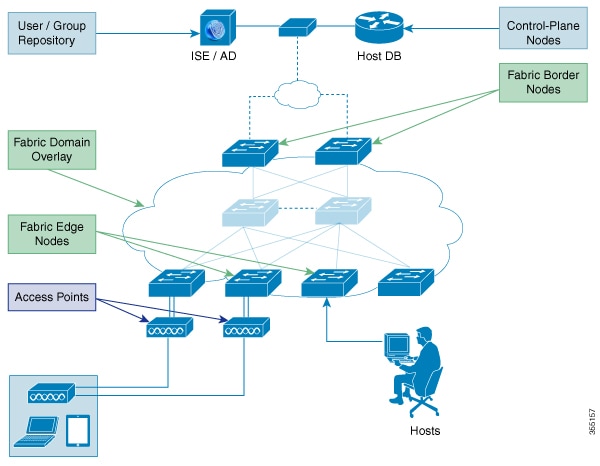
The following is a description of the fabric domain elements illustrated in the figure.
-
Fabric Edge Devices—Provide connectivity to users and devices that connect to the fabric domain. Fabric edge devices identify and authenticate end points, and register end-point ID information in the fabric host-tracking database. These devices encapsulate at ingress and decapsulate at egress, to forward traffic to and from the end points connected to the fabric domain.
-
Fabric Control-Plane Devices—Provide overlay reachability information and end points-to-routing locator mapping, in the host-tracking database. A control-plane device receives registrations from fabric edge devices having local end points, and resolves requests from edge devices to locate remote end points. You can configure up to three control-plane devices-internally (a fabric border device) and externally (a designated control-plane device, such as Cisco CSR1000v), to allow redundancy in your network.
-
Fabric Border Devices — Connect traditional Layer 3 networks or different fabric domains to the local domain, and translate reachability and policy information, such as virtual routing and forwarding (VRF) and SGT information, from one domain to another.
-
Virtual Contexts—Provide virtualization at the device level, using VRF to create multiple instances of Layer 3 routing tables. Contexts or VRFs provide segmentation across IP addresses, allowing for overlapped address space and traffic separation. You can configure up to 32 contexts in the fabric domain.
- Host-Pools—Group end points that are present in the fabric domain into IP pools, and identify them with a VLAN ID and an IP subnet.
Campus Fabric Configuration Guidelines
Consider the following guidelines and limitations when configuring campus fabric elements:
-
Configure no more than 3 control-plane devices in each fabric domain.
-
Each fabric edge device supports up to 2000 hosts.
-
Each control-plane device supports up to 5000 fabric edge device registrations.
-
Configure no more than 32 virtual contexts in each fabric domain.
How to Configure Fabric Overlay
Configuring Fabric Edge Devices
Follow these steps to configure fabric edge devices:
Before you begin
Configure a loopback0 IP address for each edge device to ensure that the device is reachable. Ensure that you run the ip lisp source-locator loopback0 command on the uplink interface.
Procedure
| Command or Action | Purpose | |
|---|---|---|
| Step 1 |
enable Example: |
Enables privileged EXEC mode.
|
| Step 2 |
configure terminal Example: |
Enters global configuration mode. |
| Step 3 |
fabric auto Example: |
Enables automatic fabric provisioning and enters automatic fabric configuration mode. |
| Step 4 |
domain {default | name fabric domain name} Example: |
Configures the default fabric domain and enters domain configuration mode. The name keyword allows you to add a new fabric domain. The no version of this command deletes the fabric domain. You can configure either the default domain, or create a new fabric domain and not both. |
| Step 5 |
control-plane ipv4 address auth_key key Example: |
|
| Step 6 |
border ipv4 address Example: |
Configures the IP address of the fabric border device, to allow the fabric edge device to communicate with the fabric border device. You can specify up to 2 border IP addresses for the edge device. |
| Step 7 |
context name name id ID Example: |
Creates a new context in the fabric domain and assigns an ID to it. Contexts or VRFs provide segmentation across IP addresses, allowing for overlapped address space and traffic separation. You can configure up to 32 contexts in the fabric domain. This step is mandatory if you want to associate a context to a host-pool. |
| Step 8 |
host-pool name name Example: |
Creates an IP pool to group endpoints in the fabric domain, and enters host-pool configuration mode. |
| Step 9 |
host-vlan ID Example: |
Configures a VLAN ID to associate with the host-pool. |
| Step 10 |
context name name Example: |
(Optional) Associates a context or a VRF with the host-pool. You can configure up to 32 contexts in your fabric domain. |
| Step 11 |
gateway IP address/ mask Example: |
Configures the routing gateway IP address and the subnet mask for the host-pool. This address and subnet mask are used to map the endpoint to the uplink interface connecting to the underlay. |
| Step 12 |
use-dhcp IP address Example: |
Configures a DHCP server address for the host-pool. You can configure multiple DHCP addresses for your host-pool. To delete a DHCP server address, use the no use-dhcp IP address command. |
| Step 13 |
exit Example: |
|
| Step 14 |
show fabric domain Example: |
Displays your fabric domain configuration. As part of this configuration, additional CLI commands are generated automatically. For more information, see Auto-Configured Commands on Fabric Edge Devices. |
Auto-Configured Commands on Fabric Edge Devices
As a part of Fabric Overlay provisioning, some LISP-based configuration, SGT (security group tag) configuration and EID to RLOC mapping configuration is auto-generated, and is displayed in your running configuration.
For example, consider this configuration scenario for an edge device (loopback address 2.1.1.1/32 ):
device(config)#fabric auto
device(config-fabric-auto)#domain default
device(config-fabric-auto-domain)#control-plane 192.168.1.4 auth-key example-key1
device(config-fabric-auto-domain)#control-plane 192.168.1.5 auth-key example-key2
device(config-fabric-auto-domain)#border 192.168.1.6
device(config-fabric-auto-domain)#context name example-context ID 10
device(config-fabric-auto-domain)#host-pool name VOICE_DOMAIN
device(config-fabric-auto-domain-host-pool)#vlan 10
device(config-fabric-auto-domain-host-pool)#context example-context
device(config-fabric-auto-domain-host-pool)#gateway 192.168.1.254/24
device(config-fabric-auto-domain-host-pool)#use-dhcp 209.165.201.6
This is sample output for your fabric edge configuration:
device#show running-config
router lisp
encapsulation vxlan
locator-set default.RLOC
IPv4-interface Loopback0 priority 10 weight 10
exit
!
eid-table default instance-id 0
exit
!
eid-table vrf example-context instance-id 10
dynamic-eid example-context.EID.VOICE_DOMAIN
database-mapping 192.168.1.0/24 locator-set default.RLOC
exit
!
exit
!
loc-reach-algorithm lsb-reports ignore
disable-ttl-propagate
ipv4 sgt
ipv4 use-petr 192.168.1.6 priority 10 weight 10
ipv4 itr map-resolver 192.168.1.4
ipv4 itr map-resolver 192.168.1.5
ipv4 itr
ipv4 etr map-server 192.168.1.4 key example-key1
ipv4 etr map-server 192.168.1.5 key example-key2
ipv4 etr
exit
!
Configuring Fabric Control-Plane Devices
Follow these steps to configure your control-plane device.
Before you begin
Configure a loopback0 IP address for each edge device to ensure that the device is reachable. Ensure that you run the ip lisp source-locator loopback0 command on the uplink interface.
Procedure
| Command or Action | Purpose | |
|---|---|---|
| Step 1 |
enable Example: |
Enables privileged EXEC mode.
|
| Step 2 |
configure terminal Example: |
Enters global configuration mode. |
| Step 3 |
fabric auto Example: |
Enables automatic fabric provisioning and enters automatic fabric configuration mode. |
| Step 4 |
domain { default | name fabric domain name} Example: |
Configures the default fabric domain and enters domain configuration mode. The name keyword allows you to add a new fabric domain. |
| Step 5 |
control-plane self auth_key key Example: |
Enables the control-plane service with the authentication key, for the configured host-prefix. |
| Step 6 |
host-prefix prefix context name name id ID Example: |
Creates a new context or a VRF and assigns an ID to it. If you don't specify a context, the default context is used. |
| Step 7 |
exit Example: |
|
| Step 8 |
show fabric domain Example: |
Displays your control-plane device configuration. As part of this configuration, additional CLI commands are automatically generated. |
Configuring Fabric Border Devices
Follow these steps to configure your device as a fabric border device.
Before you begin
Configure a loopback0 IP address for each edge device to ensure that the device is reachable. Ensure that you run the ip lisp source-locator loopback0 command on the uplink interface.
Procedure
| Command or Action | Purpose | |
|---|---|---|
| Step 1 |
enable Example: |
Enables privileged EXEC mode.
|
| Step 2 |
configure terminal Example: |
Enters global configuration mode. |
| Step 3 |
fabric auto Example: |
Enables automatic fabric provisioning and enters automatic fabric configuration mode. |
| Step 4 |
domain { default | name fabric domain name} Example: |
Configures the default fabric domain and enters domain configuration mode. The name keyword allows you to add a new fabric domain. |
| Step 5 |
control-plane ipv4 address auth_key key Example: |
Configures the IP address and the authentication key of the control-plane device, to allow the fabric border device to communicate with the control-plane device. |
| Step 6 |
border self Example: |
Enables the device as a fabric border device. |
| Step 7 |
context name name idID Example: |
Creates a new context or VRF and assigns a new ID to it. If you don't configure a context, the default context is used. |
| Step 8 |
host-prefix prefix context name name Example: |
Creates a host-prefix or a subnet mask with the context. |
| Step 9 |
exit Example: |
|
| Step 10 |
show fabric domain Example: |
Displays your fabric border device configuration. |
Security Group Tags and Policy Enforcement in Campus Fabric
Campus Fabric overlay propagates source group tags (SGTs) across devices in the fabric domain. Packets are encapsulated using virtual extensible LAN (VXLAN) and carry the SGT information in the header. When you configure an edge device, theipv4 sgt command is auto-generated. The SGT mapped to the IP address of the edge device is carried within the encapsulated packet and propagated to the destination device, where the packet is decapsulated and the Source Group Access Control List (SGACL) policy is enforced.
For more information on Cisco TrustSec and Source Group Tags, see the Cisco TrustSec Switch Configuration Guide
Multicast Using Campus Fabric Overlay
 Note |
Only Protocol Independent Multicast (PIM) Sparse Mode and PIM Source Specific Multicast (SSM) are supported in Campus Fabric; dense mode is not supported. |
Configuring Multicast PIM Sparse Mode in Campus Fabric
Procedure
| Command or Action | Purpose | |
|---|---|---|
| Step 1 |
enable Example: |
Enables privileged EXEC mode.
|
| Step 2 |
configure terminal Example: |
Enters global configuration mode. |
| Step 3 |
ip multicast-routing Example: |
Enables IP multicast routing. |
| Step 4 |
ip pim rp-addressrp address Example: |
Statically configures the address of a Protocol Independent Multicast (PIM) rendezvous point (RP) for multicast groups. |
| Step 5 |
interface LISP interface number Example: |
Specifies the LISP interface and the subinterface on which to enable Protocol Independent Multicast (PIM) sparse mode. |
| Step 6 |
ip pim sparse-mode Example: |
Enables Protocol Independent Multicast (PIM) on the interface for sparse-mode operation. |
| Step 7 |
exit Example: |
Exits interface configuration mode and enters global configuration mode. |
| Step 8 |
interfaceinterface typeinterface number Example: |
Configures the interface facing the endpoint, and enters interface configuration mode. |
| Step 9 |
ip pim sparse-mode Example: |
Enables Protocol Independent Multicast (PIM) on interface facing the fabric domain for sparse-mode operation. |
| Step 10 |
end |
Ends the current configuration session and returns to privileged EXEC mode. |
| Step 11 |
show ip mroutemulticast ip-address |
Verifies the multicast routes on the device. |
| Step 12 |
pingmulticast ip-address |
Verifies basic multicast connectivity by pinging the multicast address. |
| Step 13 |
show ip mfib |
Displays the forwarding entries and interfaces in the IPv4 Multicast Forwarding Information Base (MFIB) |
Configuring Multicast PIM SSM in Campus Fabric
Procedure
| Command or Action | Purpose | |
|---|---|---|
| Step 1 |
enable Example: |
Enables privileged EXEC mode.
|
| Step 2 |
configure terminal Example: |
Enters global configuration mode. |
| Step 3 |
ip multicast-routing Example: |
Enables IP multicast routing. |
| Step 4 |
ip pim ssm {default | range { access-list-number | access-list-name Example: |
Defines the Source Specific Multicast (SSM) range of IP multicast addresses. |
| Step 5 |
interface LISP interface number Example: |
Specifies the LISP interface and the subinterface on which to enable Protocol Independent Multicast (PIM) sparse mode. |
| Step 6 |
ip pim sparse-mode Example: |
Enables Protocol Independent Multicast (PIM) on the specified interface for sparse-mode operation. |
| Step 7 |
exit Example: |
Exits interface configuration mode and enters global configuration mode. |
| Step 8 |
interfaceinterface typeinterface number Example: |
|
| Step 9 |
ip pim sparse-mode Example: |
Enables Protocol Independent Multicast (PIM) on interface facing the fabric domain for sparse-mode operation. |
| Step 10 |
ip igmp version 3 Example: |
Configures IGMP version 3 on the interface. |
| Step 11 |
end |
Ends the current configuration session and returns to privileged EXEC mode. |
| Step 12 |
show ip mroutemulticast ip-address |
Verifies the multicast routes on the device. |
| Step 13 |
pingmulticast ip-address |
Verifies basic multicast connectivity by pinging the multicast address. |
| Step 14 |
show ip mfib |
Displays the forwarding entries and interfaces in the IPv4 Multicast Forwarding Information Base (MFIB) |
Data Plane Security in Campus Fabric
Campus Fabric Data Plane Security ensures that only traffic from within a fabric domain can be decapsulated, by an edge device at the destination. Edge and border devices in the fabric domain validate that the source Routing Locator (RLOC), or the uplink interface address, carried by the data packet is a member of the fabric domain.
Data Plane Security ensures that the edge device source addresses in the encapsulated data packets cannot be spoofed. Packets from outside the fabric domain carry invalid source RLOCs that are blocked during decapsulation by edge and border devices.
Configuring Data Plane Security on Edge Devices
Before you begin
-
Configure a loopback0 IP address for each edge device to ensure that the device is reachable.
Ensure that you apply the ip lisp source-locator loopback0 command to the uplink interface.
-
Ensure that your underlay configuration is set up.
-
Ensure that you have configured edge, control-plane, and border devices.
Procedure
| Command or Action | Purpose | |
|---|---|---|
| Step 1 |
configure terminal Example: |
Enters global configuration mode. |
| Step 2 |
router lisp Example: |
Enters LISP configuration mode. |
| Step 3 |
decapsulation filter rloc source member Example: |
Enables the validation of the source RLOC (uplink interface) addresses of encapsulated packets in the fabric domain. |
| Step 4 |
exit Example: |
Exits LISP configuration mode and returns to global configuration mode. |
| Step 5 |
show lisp [session [ established] | vrf [ vrf-name [session [peer-address]]]] Example: |
|
| Step 6 |
show lisp decapsulation filter [ IPv4-rloc-address | IPv6-rloc-address] [ eid-table eid-table-vrf | instance-id iid] Example: |
|
Configuring Data Plane Security on Control Plane Devices
Before you begin
-
Configure a loopback0 IP address for each control plane device to ensure that the device is reachable. Ensure
that you apply the ip lisp source-locator loopback0 command to the uplink interface.
-
Ensure that your underlay configuration is set up.
-
Ensure that you have configured edge, control-plane, and border devices.
Procedure
| Command or Action | Purpose | |
|---|---|---|
| Step 1 |
enable Example: |
Enables privileged EXEC mode.
|
| Step 2 |
configure terminal Example: |
Enters global configuration mode. |
| Step 3 |
router lisp Example: |
Enters LISP configuration mode. |
| Step 4 |
map-server rloc members distribute Example: |
Enables the distribution of the list of EID prefixes, to the edge devices in the fabric domain. |
| Step 5 |
exit Example: |
Exits LISP configuration mode. |
| Step 6 |
show lisp [session [ established] | vrf [ vrf-name [session [peer-address]]]] Example: |
|
| Step 7 |
show lisp decapsulation filter [ IPv4-rloc-address | IPv6-rloc-address] [ eid-table eid-table-vrf | instance-id iid] Example: |
|
Configuring Data Plane Security on Border Devices
Before you begin
-
Configure a loopback0 IP address for each border device to ensure that the device is reachable. Ensure
that you apply the ip lisp source-locator loopback0 command to the uplink interface.
-
Ensure that your underlay configuration is set up.
-
Ensure that you have configured edge, control-plane, and border devices.
Procedure
| Command or Action | Purpose | |
|---|---|---|
| Step 1 |
enable Example: |
Enables privileged EXEC mode.
|
| Step 2 |
configure terminal Example: |
Enters global configuration mode. |
| Step 3 |
router lisp Example: |
Enters LISP configuration mode. |
| Step 4 |
decapsulation filter rloc source member Example: |
Enables the validation of the source RLOC (uplink interface) addresses of encapsulated packets in the fabric domain. |
| Step 5 |
exit Example: |
Exits LISP configuration mode and returns to global configuration mode. |
| Step 6 |
show lisp [session [ established] | vrf [ vrf-name [session [peer-address]]]] Example: |
|
| Step 7 |
show lisp decapsulation filter [ IPv4-rloc-address | IPv6-rloc-address] [ eid-table eid-table-vrf | instance-id iid] Example: |
|
Campus Fabric Configuration Examples
This is sample output for the show running-configuration command for an edge configuration:
device#show running-config
fabric auto
!
domain default
control-plane 198.51.100.2 auth-key example-key1
border 192.168.1.6
context name eg-context id 10
!
host-pool name VOICE_VLAN
context eg-context
vlan 10
gateway 192.168.1.254/24
use-dhcp 172.10.1.1
exit
exit
router lisp
locator-set default.RLOC
IPv4-interface Loopback0 priority 10 weight 10
exit
!
encapsulation vxlan
eid-table default instance-id 0
exit
!
eid-table vrf eg-context instance-id 10
dynamic-eid eg-context.EID.VOICE_VLAN
database-mapping 192.168.1.0/24 locator-set default.RLOC
exit
!
exit
!
loc-reach-algorithm lsb-reports ignore
disable-ttl-propagate
ipv4 sgt
ipv4 use-petr 192.168.1.6 priority 10 weight 10
ipv4 itr map-resolver 192.168.1.4
ipv4 itr map-resolver 192.168.1.5
ipv4 itr
ipv4 etr map-server 192.168.1.4 key example-key1
ipv4 etr map-server 192.168.1.5 key example-key2
ipv4 etr
exit
This is sample output for the show running-configuration command for a control-plane configuration:
!
fabric auto
domain default
control-plane auth-key example-key1
exit
!
ip vrf eg-context
!
vlan name VOICE_VLAN id 10
interface Vlan 10
ip address 192.168.1.254 255.255.255.0
ip helper–address global 172.10.1.1
no ip redirects
ip local-proxy-arp
ip route-cache same-interface
no lisp mobility liveness test
lisp mobility default.EID.VOICE_VLAN
router lisp
eid-table default
dynamic-default.EID.VOICE_VLAN
database-mapping 192.168.1.0/24 locator-set FD_DEFAULT.RLOC
router lisp
site FD_Default
authentication-key example-key1
exit
ipv4 map-server
ipv4 map-resolver
exit
This is sample output for the show running-configuration command for a border device configuration:
!fabric auto
!
domain default
control-plane 198.51.100.2 auth-key example-key1
border self
context name eg-context id 10
!
host-prefix 192.168.1.0/24 context name eg-context
!
host-pool name Voice
context eg-context
use-dhcp 172.10.1.1
exit
!
host-pool name doc
exit
exit
exit
router lisp
encapsulation vxlan
loc-reach-algorithm lsb-reports ignore
disable-ttl-propagate
ipv4 sgt
ipv4 proxy-etr
ipv4 proxy-itr 1.1.1.1
ipv4 itr map-resolver 198.51.100.2
ipv4 etr map-server 198.51.100.2 key example-key1
exit Feedback