Installation Note for the Catalyst 4500 Series Center Mount System
Available Languages
Table of Contents
Installation Note for the Catalyst 4500 Series Center Mount System
Rack-Mounting Catalyst4500 Series Switches
System Ground Connection Guidelines
Obtaining Documentation and Submitting a Service Request
Installation Note for the Catalyst 4500 Series Center Mount System
WS-X4503-23CNTR= C4503 Center Mount 23 Inch Rack Kit L/R
WS-X4503-FILTER= C4503 Center Mount 23 Inch Filter (1 Set)
WS-X4506-23CNTR= C4506 Center Mount 23 Inch Rack Kit L/R
WS-X4506-FILTER= C4506 Center Mount 23 Inch Filter (1 Set)
WS-X4507-23CNTR= C4507R Center Mount 23 Inch Rack Kit L/R
WS-X4507-FILTER= C4507 Center Mount 23 Inch Filter (1 Set)
Safety Overview
Throughout this publication, safety warnings appear in procedures that can harm you if performed incorrectly. A warning symbol precedes each warning statement.

Warning![]() This unit is intended for installation in restricted access areas. A restricted access area can be accessed only through the use of a special tool, lock and key, or other means of security. Statement 1017
This unit is intended for installation in restricted access areas. A restricted access area can be accessed only through the use of a special tool, lock and key, or other means of security. Statement 1017

Warning![]() Only trained and qualified personnel should be allowed to install, replace, or service this equipment. Statement 1030
Only trained and qualified personnel should be allowed to install, replace, or service this equipment. Statement 1030

Warning![]() To prevent personal injury or damage to the chassis, never attempt to lift or tilt the chassis using the handles on modules (such as power supplies, fans, or cards); these types of handles are not designed to support the weight of the unit. Statement 1032
To prevent personal injury or damage to the chassis, never attempt to lift or tilt the chassis using the handles on modules (such as power supplies, fans, or cards); these types of handles are not designed to support the weight of the unit. Statement 1032
This document describes how to install Catalyst 4500 series switches in a two-post rack using the optional brackets. For first-time installations, perform the procedures in the following sections in the order listed: For all other information regarding installing a Catalyst 4500 series switch, refer to the Catalyst 4500 Series Installation Guide at :
http://www.cisco.com/en/US/docs/switches/lan/catalyst4500/hardware/installation/guide/78-14409-08/4500inst.html
Rack-Mounting the Switch
This rack-mount kit is used for mounting the switch in a standard 23-inch (58.4 cm) equipment rack with two unobstructed outer posts. This kit is not suitable for racks with obstructions (such as a power strip) that could impair access to the field-replaceable units (FRUs) of the switch.
Required Installation Tools
You will need the following tools and equipment to install the chassis in a rack:
- Number 1 and number 2 Phillips screwdrivers to tighten the captive installation screws on most systems
- 3/16-inch flat-blade screwdriver for the captive installation screws on the supervisor engine and switching modules on some systems
- Antistatic mat or antistatic foam in case you need to remove switching modules to troubleshoot the installation
- Rack-mount kit
- Tape measure
- Level
- Your own electrostatic discharge (ESD) grounding strap or the disposable ESD strap included with the system
Rack-Mounting Catalyst 4500 Series Switches
Follow these steps to install a Catalyst 4500 series switch in a rack:
Step 1![]() Prepare for installation as follows:
Prepare for installation as follows:
a.![]() Place the chassis on the floor or on a sturdy table as close as possible to the rack. Leave enough clearance to allow you to move around the chassis.
Place the chassis on the floor or on a sturdy table as close as possible to the rack. Leave enough clearance to allow you to move around the chassis.
b.![]() Open the rack-mount kit and check the component checklist in Table 1 to verify that all parts are included.
Open the rack-mount kit and check the component checklist in Table 1 to verify that all parts are included.

Note![]() Some equipment racks provide a power strip along the length of one of the rear posts. If your rack has this feature, consider the position of the strip when planning fastener points. Before installing the brackets on the chassis, determine whether to install the chassis from the front or the rear of the rack.
Some equipment racks provide a power strip along the length of one of the rear posts. If your rack has this feature, consider the position of the strip when planning fastener points. Before installing the brackets on the chassis, determine whether to install the chassis from the front or the rear of the rack.
Step 2![]() Install the brackets, which connect the chassis to the rack, as follows:
Install the brackets, which connect the chassis to the rack, as follows:
a.![]() Remove the screws from the front of the switch side-cover panels.
Remove the screws from the front of the switch side-cover panels.
b.![]() Attach the brackets to the left and right sides of the switch using the M4 Phillips pan-head screws provided in the rack-mount kit.
Attach the brackets to the left and right sides of the switch using the M4 Phillips pan-head screws provided in the rack-mount kit.

Note![]() Be sure to install the bracket with the filter element on the side of the switch opposite from the fan tray, as is shown in the illustrations. It is possible to reverse the brackets and install the filter on the wrong side, losing the advantage of having the filter.
Be sure to install the bracket with the filter element on the side of the switch opposite from the fan tray, as is shown in the illustrations. It is possible to reverse the brackets and install the filter on the wrong side, losing the advantage of having the filter.
See Figure 1 for the Catalyst 4503 switch, Figure 2 for the Catalyst 4506 switch, Figure 3 for the Catalyst 4507R switch, or Figure 4 for the Catalyst 4510R switch.
Figure 1 Center Mount Brackets on the Catalyst 4503 Switch

Figure 2 Center Mount Brackets on the Catalyst 4506 Switch

Figure 3 Center Mount Brackets on the Catalyst 4507R Switch
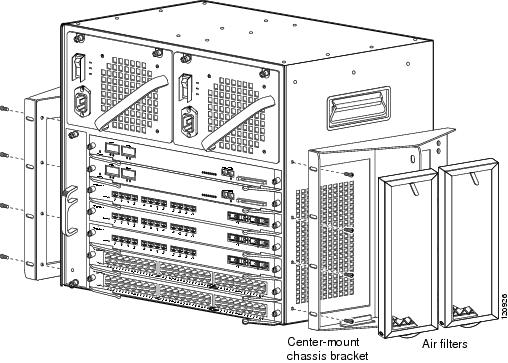
Figure 4 Center Mount Brackets on the Catalyst 4510R Switch

c.![]() Attach the filters. To attach the front filter, slide the bottom of the filter into the bracket, pull the tab down, and push it into the center mounting bracket. Slide the rear filter in parallel to the chassis from the rear of the switch. The filters should cover the air intake grill of the switch.
Attach the filters. To attach the front filter, slide the bottom of the filter into the bracket, pull the tab down, and push it into the center mounting bracket. Slide the rear filter in parallel to the chassis from the rear of the switch. The filters should cover the air intake grill of the switch.

Note![]() The filter should be replaced every 3-6 months, or more often if needed.
The filter should be replaced every 3-6 months, or more often if needed.
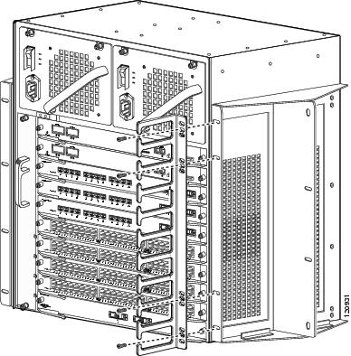
d.![]() Attach the cable guide, if needed, using the M3 screws provided in the cable management kit. The cable guide attaches to the mounting bracket. Attach the cable guide to the right side of the switch to prevent the cables from obscuring module LEDs.
Attach the cable guide, if needed, using the M3 screws provided in the cable management kit. The cable guide attaches to the mounting bracket. Attach the cable guide to the right side of the switch to prevent the cables from obscuring module LEDs.
See Figure 5 for the Catalyst 4503 switch, Figure 6 for the Catalyst 4506 switch, Figure 7 for the Catalyst 4507R switch, or Figure 8 for the Catalyst 4510R switch.
Figure 5 Attaching the Cable Guide to the Catalyst 4503 Switch

Figure 6 Attaching the Cable Guide to the Catalyst 4506 Switch

Figure 7 Attaching the Cable Guide to the Catalyst 4507R Switch

Figure 8 Attaching the Cable Guide to the Catalyst 4510R Switch
Step 3![]() Install the chassis in the rack as follows:
Install the chassis in the rack as follows:
a.![]() Insert the rear of the chassis between the mounting posts.
Insert the rear of the chassis between the mounting posts.
See Figure 9 for the Catalyst 4503 switch.
See Figure 10 for the Catalyst 4506 switch.
See Figure 11 for the Catalyst 4507R switch.
See Figure 12 for the Catalyst 4510R switch.
b.![]() Align the mounting holes in the bracket with the mounting holes in the equipment rack.
Align the mounting holes in the bracket with the mounting holes in the equipment rack.
c.![]() Secure the chassis using at least six (three per side) 12-24 x 3/4-inch screws through the elongated holes in the L bracket and into the threaded holes in the mounting post.
Secure the chassis using at least six (three per side) 12-24 x 3/4-inch screws through the elongated holes in the L bracket and into the threaded holes in the mounting post.
d.![]() Use a tape measure and level to ensure that the chassis is installed straight and level.
Use a tape measure and level to ensure that the chassis is installed straight and level.
Figure 9 Installing a Catalyst 4503 Switch in the Rack

Figure 10 Installing a Catalyst 4506 Switch in the Rack

Figure 11 Installing a Catalyst 4507R Switch in the Rack
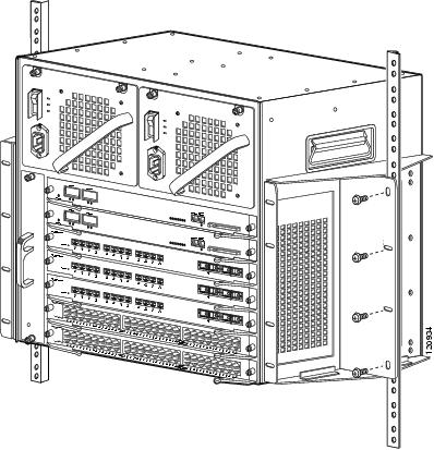
Figure 12 Installing a Catalyst 4510R Switch in the Rack

Step 4![]() Make sure that the ejector levers are completely closed and the supervisor engine and switching modules are installed securely.
Make sure that the ejector levers are completely closed and the supervisor engine and switching modules are installed securely.
Step 5![]() Tighten any loose captive installation screws on the supervisor engine and the switching module.
Tighten any loose captive installation screws on the supervisor engine and the switching module.
Step 6![]() Connect the switch to an appropriate ground. Refer to the “System Ground Connection Guidelines” section. The system must have a ground connection before power is supplied to the switch.
Connect the switch to an appropriate ground. Refer to the “System Ground Connection Guidelines” section. The system must have a ground connection before power is supplied to the switch.
Step 7![]() Connect the power supply cords.
Connect the power supply cords.
The switch comes on when the cords are connected and the power switches (if present) are turned on.
This completes the installation of the Catalyst 4500 series switches.
System Ground Connection Guidelines
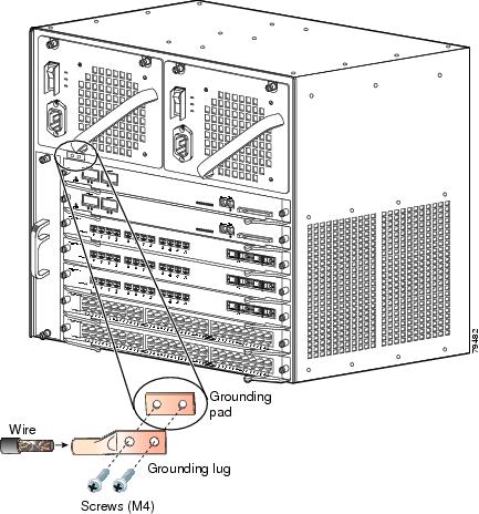
A grounding pad with two system (earth) grounding holes is provided in an enclosure near the left power supply on the Catalyst 4500 series switches. See Figure 13 for the location of the grounding holes on the Catalyst 4503 switch, Figure 14 for the location on the Catalyst 4506 switch, Figure 15 for the location on the Catalyst 4507R switch, and Figure 16 for the location on the Catalyst 4510R switch.
Figure 13 Catalyst 4503 Grounding Holes

Figure 14 Catalyst 4506 Grounding Holes

Figure 15 Catalyst 4507R Grounding Holes
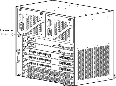
Figure 16 Catalyst 4510R Grounding Holes
Parts and Required Tools

Note![]() The parts and required tools described in this section are not available from Cisco Systems.
The parts and required tools described in this section are not available from Cisco Systems.
To make an adequate grounding connection, you will need the following parts and tools:
- Grounding lug—The grounding lug must have two grounding holes.
- Two M4 (metric) hex-head screws.
- One grounding wire (6 AWG recommended)—The length of the grounding wires depends on the location of your switch within the site and its proximity to proper grounding facilities.
- Number 2 Phillips screwdriver.
- Crimping tool—This tool must be large enough to accommodate the girth of the grounding lug when you crimp the grounding cable into the lug.
- Wire-stripping tool.
Connecting System Ground
This section describes how to connect the Catalyst 4500 series switches to earth ground. The system ground connection is required if FXS modules are installed or if this equipment is installed in a US or European Central Office.You must complete this procedure before connecting system power or turning on your switch.
To attach the grounding lug and cable to the grounding pad on your Catalyst 4500 series switch, follow these steps:
Step 1![]() Using a wire-stripping tool, remove approximately 0.75 inches (19 mm) of the covering from the end of the grounding wire.
Using a wire-stripping tool, remove approximately 0.75 inches (19 mm) of the covering from the end of the grounding wire.
Step 2![]() Insert the stripped end of the grounding wire into the open end of the grounding lug (Figure 17).
Insert the stripped end of the grounding wire into the open end of the grounding lug (Figure 17).
Step 3![]() Using a crimping tool, secure the grounding wire in place in the grounding lug.
Using a crimping tool, secure the grounding wire in place in the grounding lug.
Step 4![]() Locate the grounding pad on the switch.
Locate the grounding pad on the switch.
See Figure 13 for the location of the grounding holes on the Catalyst 4503 switch, Figure 14 for the location on the Catalyst 4506 switch, Figure 15 for the location on the Catalyst 4507R switch, and Figure 16 for the location on the Catalyst 4510R switch.
Figure 17 Connecting System Ground on the Switch

Step 5![]() Remove the label that covers the grounding pad.
Remove the label that covers the grounding pad.
Step 6![]() Place the grounding lug against the grounding pad, aligning the holes. Insert the two M4 screws through the holes in the grounding lug and grounding pad (Figure 15 and Figure 17).
Place the grounding lug against the grounding pad, aligning the holes. Insert the two M4 screws through the holes in the grounding lug and grounding pad (Figure 15 and Figure 17).
Ensure that the grounding lug and the attached wire will not interfere with other switch hardware or rack equipment.
Step 7![]() Tighten the screws to secure the grounding lug to the grounding pad.
Tighten the screws to secure the grounding lug to the grounding pad.
Step 8![]() Repeat Steps 1 through 3 to prepare the other end of the grounding wire and connect it to an appropriate grounding point at your site to ensure adequate earth ground for the switch.
Repeat Steps 1 through 3 to prepare the other end of the grounding wire and connect it to an appropriate grounding point at your site to ensure adequate earth ground for the switch.
Obtaining Documentation and Submitting a Service Request
For information on obtaining documentation, submitting a service request, and gathering additional information, see the monthly What’s New in Cisco Product Documentation, which also lists all new and revised Cisco technical documentation, at:
http://www.cisco.com/en/US/docs/general/whatsnew/whatsnew.html
Subscribe to the What’s New in Cisco Product Documentation as a Really Simple Syndication (RSS) feed and set content to be delivered directly to your desktop using a reader application. The RSS feeds are a free service and Cisco currently supports RSS version 2.0.

Contact Cisco
- Open a Support Case

- (Requires a Cisco Service Contract)


 Feedback