- Release 15.4SY Supervisor Engine 6T Software Configuration Guide
- Preface
- Product Overview
- Command-Line Interfaces
- Smart Port Macros
- Virtual Switching Systems (VSS)
- Enhanced Fast Software Upgrade (eFSU)
- Fast Software Upgrades
- Stateful Switchover (SSO)
- Non-Stop Forwarding (NSF)
- RPR Supervisor Engine Redundancy
- Interface Configuration
- UniDirectional Link Detection (UDLD)
- Instant Access
- EnergyWise
- Power Management
- Environmental Monitoring
- Online Diagnostics
- Onboard Failure Logging (OBFL)
- Switch Fabric Functionality
- Cisco IP Phone Support
- Power over Ethernet
- Layer 2 LAN Port Configuration
- Flex Links
- EtherChannels
- IEEE 802.1ak MVRP and MRP
- VLAN Trunking Protocol (VTP)
- VLANs
- Private VLANs (PVLANs)
- Private Hosts
- IEEE 802.1Q Tunneling
- Layer 2 Protocol Tunneling
- Spanning Tree Protocols (STP, MST)
- Optional STP Features
- IP Unicast Layer 3 Switching
- Policy Based Routing (PBR)
- Layer 3 Interface Configuration
- Unidirectional Ethernet (UDE) and unidirectional link routing (UDLR)
- Multiprotocol Label Switching (MPLS)
- MPLS VPN Support
- Ethernet over MPLS (EoMPLS)
- L2VPN Advanced VPLS (A-VPLS)
- Ethernet Virtual Connections (EVC)
- Layer 2 over Multipoint GRE (L2omGRE)
- Campus Fabric
- IPv4 Multicast Layer 3 Features
- IPv4 Multicast IGMP Snooping
- IPv4 PIM Snooping
- IPv4 Multicast VLAN Registration (MVR)
- IPv4 IGMP Filtering
- IPv4 Router Guard
- IPv4 Multicast VPN Support
- IPv6 Multicast Layer 3 Features
- IPv6 MLD Snooping
- NetFlow Hardware Support
- System Event Archive (SEA)
- Backplane Platform Monitoring
- Local SPAN, RSPAN, and ERSPAN
- SNMP IfIndex Persistence
- Top-N Reports
- Layer 2 Traceroute Utility
- Mini Protocol Analyzer
- PFC QoS Guidelines and Restrictions
- PFC QoS Overview
- PFC QoS Classification, Marking, and Policing
- PFC QoS Policy Based Queueing
- PFC QoS Global and Interface Options
- AutoQoS
- MPLS QoS
- PFC QoS Statistics Data Export
- Cisco IOS ACL Support
- Cisco TrustSec (CTS)
- AutoSecure
- MAC Address-Based Traffic Blocking
- Port ACLs (PACLs)
- VLAN ACLs (VACLs)
- Policy-Based Forwarding (PBF)
- Denial of Service (DoS) Protection
- Control Plane Policing (CoPP)
- Dynamic Host Configuration Protocol (DHCP) Snooping
- IP Source Guard
- Dynamic ARP Inspection (DAI)
- Traffic Storm Control
- Unknown Unicast and Multicast Flood Control
- IEEE 802.1X Port-Based Authentication
- Configuring Web-Based Authentication
- Port Security
- Lawful Intercept
- Online Diagnostic Tests
- Prerequisites for VSS
- Restrictions for VSS
- Information About Virtual Switching Systems
- Configuring Easy VSS
- Converting to a VSS
- VSS Conversion Overview
- Backing Up the Standalone Configuration
- Configuring SSO and NSF
- Assigning Virtual Switch Domain and Switch Numbers
- Configuring the VSL Port Channel
- Configuring the VSL Ports
- Verifying the PFC Operating Mode
- Converting the Chassis to Virtual Switch Mode
- Auto-Configuring the Standby VSL Information
- (Optional) Configuring Standby Chassis Modules
- Displaying VSS Information
- Converting a VSS to Standalone Chassis
- Configuring VSS Parameters
- Configuring VSL Switch Priority
- Configuring the PFC Mode
- Configuring a VSL
- Configuring VSL Encryption
- Displaying VSL Information
- Configuring VSL QoS
- Subcommands for VSL Port Channels
- Subcommands for VSL Ports
- Configuring the Router MAC Address Assignment
- Configuring Deferred Port Activation During Standby Recovery
- Configuring Multichassis EtherChannels
- Configuring Port Load Share Deferral on the Peer Switch
- Configuring Dual-Active Detection
Virtual Switching Systems
- Prerequisites for VSS
- Restrictions for VSS
- Information About Virtual Switching Systems
- Default Settings for VSS
- How to Configure a VSS
- How to Upgrade a VSS

Note ●![]() For complete syntax and usage information for the commands used in this chapter, see these publications:
For complete syntax and usage information for the commands used in this chapter, see these publications:
http://www.cisco.com/en/US/products/ps11846/prod_command_reference_list.html
- Cisco IOS Release 15.4SY supports only Ethernet interfaces. Cisco IOS Release 15.4SY does not support any WAN features or commands.
http://www.cisco.com/en/US/products/hw/switches/ps708/tsd_products_support_series_home.html
Participate in the Technical Documentation Ideas forum
Prerequisites for VSS
The VSS configurations in the startup-config file must match on both chassis.
Restrictions for VSS
- General VSS Restrictions
- VSL Restrictions
- Multichassis EtherChannel (MEC) Restrictions
- Dual-Active Detection Restrictions
General VSS Restrictions
- VSS mode does not support supervisor engine redundancy within a chassis.
- If you configure a new value for switch priority, the change takes effect only after you save the configuration file and perform a restart.
- Out-of-band MAC address table synchronization among DFC-equipped switching modules (the mac address-table synchronize command) is enabled automatically in VSS mode, which is the recommended configuration.
- Because the output of the show running-config command on ICS supervisor engines could be out of sync with the active supervisor engine, ICS supervisor engines do not support the show running-config command. The active and standby supervisor engines support the show running-config command.
VSL Restrictions
- For line redundancy, we recommend configuring at least two ports per switch for the VSL. For module redundancy, the two ports can be on different switching modules in each chassis.
- The no platform qos channel-consistency command is automatically applied when you configure the VSL. Do not remove this command.
- VSL ports cannot be Mini Protocol Analyzer sources (the monitor... capture command). Monitor capture sessions cannot be started if a source is the VSL on the port channel of the standby switch. The following message is displayed when a remote VSL port channel on the standby switch is specified and you attempt to start the monitor capture:
The following message is displayed when a scheduled monitor capture start fails because a source is a remote VSL port channel:
Multichassis EtherChannel (MEC) Restrictions
- All links in an MEC must terminate locally on the active or standby chassis of the same virtual domain.
- For an MEC using the LACP control protocol, the minlinks command argument defines the minimum number of physical links in each chassis for the MEC to be operational.
- For an MEC using the LACP control protocol, the maxbundle command argument defines the maximum number of links in the MEC across the whole VSS.
- MEC supports LACP 1:1 redundancy. For additional information about LACP 1:1 redundancy, refer to the “Information about LACP 1:1 Redundancy” section.
- An MEC can be connected to another MEC in a different VSS domain.
- Ports on the supervisor engines are not stateful and will experience a reset across switchovers (see the “Switchover Process Restrictions” section).
- With an MEC that includes supervisor engine ports configured on a VSS that supports the VSS Quad-Sup SSO (VS4O) feature, be aware of CSCuh51005.
Dual-Active Detection Restrictions
- If Flex Links are configured on the VSS, use PAgP dual-active detection.
- For dual-active detection link redundancy, configure at least two ports per switch for dual-active detection. For module redundancy, the two ports can be on different switching modules in each chassis, and should be on different modules than the VSL, if feasible.
- When you configure dual-active fast hello mode, all existing configurations are removed automatically from the interface except for these commands:
- ASIC-specific QoS commands are not configurable on dual-active detection fast hello ports directly, but are allowed to remain on the fast hello port if the commands were configured on another non-fast hello port in that same ASIC group. For a list of these commands, see Chapter61, “Restrictions for PFC QoS”
Information About Virtual Switching Systems
- VSS Overview
- VSS Redundancy
- Multichassis EtherChannels
- Packet Handling
- System Monitoring
- Convert Port Mode
- Dual-Active Detection
- VSS Initialization
VSS Overview
VSS Topology
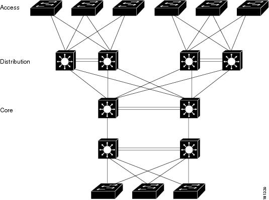
Network operators increase network reliability by configuring switches in redundant pairs and by provisioning links to both switches in the redundant pair. Figure 4-1 shows a typical network configuration. Redundant network elements and redundant links can add complexity to network design and operation. Virtual switching simplifies the network by reducing the number of network elements and hiding the complexity of managing redundant switches and links.
VSS mode combines a pair of switches into a single network element. VSS mode manages the redundant links, which externally act as a single port channel.
VSS mode simplifies network configuration and operation by reducing the number of Layer 3 routing neighbors and by providing a loop-free Layer 2 topology.
Figure 4-1 Typical Network Design
Key Concepts
Virtual Switching System
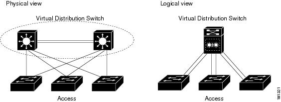
A VSS combines a pair of switches into a single network element. For example, a VSS in the distribution layer of the network interacts with the access and core networks as if it were a single switch. See Figure 4-2.
An access switch connects to both chassis of the VSS using one logical port channel. VSS mode manages redundancy and load balancing on the port channel. This capability enables a loop-free Layer 2 network topology. VSS mode also simplifies the Layer 3 network topology because VSS mode reduces the number of routing peers in the network.
Figure 4-2 VSS in the Distribution Network
Active and Standby Chassis
When you create or restart a VSS, the peer chassis negotiate their roles. One chassis becomes the active chassis, and the other chassis becomes the standby.
The active chassis controls the VSS. It runs the Layer 2 and Layer 3 control protocols for the switching modules on both chassis. The active chassis also provides management functions for the VSS, such as module online insertion and removal (OIR) and the console interface.
The active and standby chassis perform packet forwarding for ingress data traffic on their locally hosted interfaces. However, the standby chassis sends all control traffic to the active chassis for processing.
You can defer the traffic load on a multichassis EtherChannel (MEC) chassis to address traffic recovery performance during the standby chassis startup. For example, Figure 4-3 represents network layout where a VSS (active and standby switches) is interacting with an upstream switch (switch 2) and a downstream switch (switch 1).
Figure 4-3 Switch Interconnected Through VSS

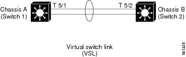
Virtual Switch Link
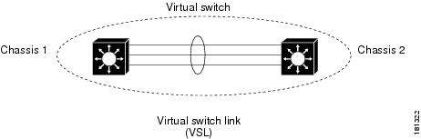
For the two chassis of the VSS to act as one network element, they need to share control information and data traffic.
The virtual switch link (VSL) is a special link that carries control and data traffic between the two chassis of a VSS, as shown in Figure 4-4. The VSL is implemented as an EtherChannel with up to eight links. The VSL gives control traffic higher priority than data traffic so that control messages are never discarded. Data traffic is load balanced among the VSL links by the EtherChannel load-balancing algorithm.
Figure 4-4 Virtual Switch Link
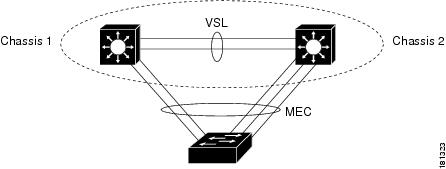
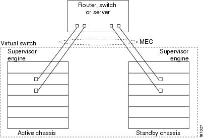
Multichassis EtherChannel (MEC)
An EtherChannel, which is configured on a port channel interface, is two or more physical links that combine to form one logical link. Layer 2 protocols operate on the EtherChannel as a single logical entity.
A MEC is a port channel with member ports on both chassis of the VSS. A connected non-VSS device views the MEC as a standard EtherChannel. See Figure 4-5.
VSS mode supports a maximum of 512 EtherChannels. This limit applies to the combined total of regular EtherChannels and MECs. Because the VSL requires two EtherChannel numbers (one for each chassis), there are 510 user-configurable EtherChannels.
Note![]() Ports on the supervisor engines are not stateful and will experience a reset across switchovers (see the “Switchover Process Restrictions” section).
Ports on the supervisor engines are not stateful and will experience a reset across switchovers (see the “Switchover Process Restrictions” section).
VSS Functionality
Redundancy and High Availability
In VSS mode, supervisor engine redundancy operates between the active and standby chassis, using stateful switchover (SSO) and nonstop forwarding (NSF). The peer chassis exchange configuration and state information across the VSL and the standby supervisor engine runs in hot standby mode.
The standby chassis monitors the active chassis using the VSL. If it detects failure, the standby chassis initiates a switchover and takes on the active role. When the failed chassis recovers, it takes on the standby role.
Note![]() Ports on the supervisor engines are not stateful and will experience a reset across switchovers (see the “Switchover Process Restrictions” section).
Ports on the supervisor engines are not stateful and will experience a reset across switchovers (see the “Switchover Process Restrictions” section).
If the VSL fails completely, the standby chassis assumes that the active chassis has failed, and initiates a switchover. After the switchover, if both chassis are active, the dual-active detection feature detects this condition and initiates recovery action. For additional information about dual-active detection, see the “Dual-Active Detection” section.
Packet Handling
The active supervisor engine runs the Layer 2 and Layer 3 protocols and features for the VSS and manages the DFC modules for both chassis.
The VSS uses VSL to communicate protocol and system information between the peer chassis and to carry data traffic between the chassis when required.
Both chassis perform packet forwarding for ingress traffic on their interfaces. If possible, ingress traffic is forwarded to an outgoing interface on the same chassis to minimize data traffic that must traverse the VSL.
Because the standby chassis is actively forwarding traffic, the active supervisor engine distributes updates to the standby supervisor engine PFC and all standby chassis DFCs.
System Management
The active supervisor engine acts as a single point of control for the VSS. For example, the active supervisor engine handles OIR of switching modules on both chassis. The active supervisor engine uses VSL to send messages to and from local ports on the standby chassis.
The command console on the active supervisor engine is used to control both chassis. In virtual switch mode, the command console on the standby supervisor engine blocks attempts to enter configuration mode.
The standby chassis runs a subset of system management tasks. For example, the standby chassis handles its own power management.
VSS Quad-Sup SSO (VS4O)
Release 15.1(1)SY1 and later releases support the VSS Quad-Sup SSO (VS4O) feature.
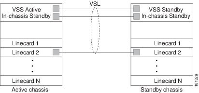
Best Practice for VSL Links Between Supervisors
If there is a VSL link from ICA to ICA supervisor engine, ICS to ICS supervisor engine, and line card to line card, the control link will always be from the line card. The next preferred control link is from ICS to ICS VSL link, and the least preferred control link is from ICA to ICA VSL link.
In case of an ISSU image upgrade, if there is no cross VSL link, the control link will always be from the ICS supervisor engine. If there is a cross VSL link, the control link can be from any of the ICA supervisor engines.
Figure 4-6 Typical VSS Quad-Supervisor Configuration

These are the quad-supervisor VSS roles:
- In-chassis active (ICA) supervisor engines—The VSS active supervisor engine in one chassis and the VSS standby supervisor engine in the other chassis are ICA supervisor engines.
If the VSS active ICA supervisor engine crashes, a switchover to the standby ICA supervisor engine in other chassis occurs. Both VSS chassis remain active. All switching modules remain active.
In the chassis with the previously active ICA supervisor engine, an SSO switchover from the previously active ICA supervisor engine to the ICS standby supervisor engine occurs and the ICS takes over as the ICA. The failed ICA reloads and becomes the ICS.
You can verify the switchover mode of the supervisor engines by entering the show module command.
- In-chassis standby (ICS) supervisor engines—The other supervisor engines are ICS supervisor engines. The supervisor engine uplinks ports are available to forward traffic.
Note![]() ICS supervisor engines do not support show commands. To avoid tracebacks, do not issue show commands on ICS supervisor engines.
ICS supervisor engines do not support show commands. To avoid tracebacks, do not issue show commands on ICS supervisor engines.
If the supervisor engine PFC modes do not match then an ICS supervisor engine is reset to ROMMON. Configure both chassis to run in the same PFC mode.
ICS supervisor engines boot in SSO standby mode, which fully initializes and configures the ICS and maintains stateful feature and user session information.
To verify the switchover mode of the supervisor engines, enter the show module command.
When not in VSS quad supervisor engine mode, if you insert a supervisor engine to be an ICS, the supervisor engine resets to update the supervisor engine number and then reboots before going online.
Quad-supervisor SSO (VS4O) supports eFSU upgrades. You can upgrade or downgrade your VSS system using ISSU. See “How to Upgrade a VSS” section for more information about eFSU upgrades.
Interface Naming Convention
In VSS mode, interfaces are specified using switch number (in addition to slot and port), because the same slot numbers are used on both chassis. For example, the interface 1/5/4 command specifies port 4 of the switching module in slot 5 of switch 1. The interface 2/5/4 command specifies port 4 on the switching module in slot 5 of switch 2.
Software Features
With some exceptions, VSS mode has feature parity with non-VSS mode. Major exceptions include:
Hardware Requirements
Chassis and Modules
VSL Hardware Requirements
The VSL EtherChannel supports only 40-Gigabit and 10-Gigabit Ethernet ports. The ports can be located on the supervisor engine (recommended) or on one of the following switching modules:
- WS-X6904-40G-2T
- WS-X6908-10GE
- WS-X6816-10T-2T
- WS-X6816-10G-2T
- C6800-32P-10G and C6800-32P-10G-XL
- C6800-16P-10G and C6800-16P-10G-XL
- C6800-8P-10G and C6800-8P-10G-XL
Use any of the 10-Gigabit or 40-Gigabit Ethernet ports on the supervisor engines to create the VSL between the two chassis.
You can add more physical links to the VSL EtherChannel by using the 40-Gigabit or 10-Gigabit Ethernet ports on switching modules that support the VSL.
Note ●![]() If you use 10-Gigabit Ethernet ports to form VSL, you can bundle a maximum of 8 links to the VSL ether channel.
If you use 10-Gigabit Ethernet ports to form VSL, you can bundle a maximum of 8 links to the VSL ether channel.
- If you use 40-Gigabit Ethernet ports to form VSL, you can bundle a maximum of 4 links to the VSL ether channel.
- For switching modules WS-X6816-10T-2T and WS-X6816-10G-2T, when using the ports on these switching module as VSL links, you must operate the ports in performance mode, not in oversubscription mode. Enter the no hw-module switch x slot y oversubscription port-group num command when configuring the switching module. If you enter the no hw-module switch switch_number slot slot_number oversubscription command to configure non-oversubscription mode (performance mode), then only ports 1, 5, 9, and 13 are configurable; the other ports on the module are disabled.
- Port-groups are independent of each other and one or more port-groups can operate in non-oversubscribed mode for VSL with the unused ports administratively shutdown, while the others can still operate in oversubscribed mode.
PFC, DFC, and CFC Requirements
Switching modules with a DFC4, or DFC4XL support VSS mode.
With a PFC4, the VSS will automatically operate in PFC4 mode, even if some of the modules have a DFC4XL. With a PFC4XL, but some modules equipped with a DFC4, you need to configure the VSS to operate in PFC4 mode. The platform hardware vsl pfc mode non-xl configuration command sets the system to operate in PFC4 mode after the next restart. See the “SSO Dependencies” section for further details about this command.
Multichassis EtherChannel Requirements
Physical links from any module with a DFC4, or DFC4XL can be used to implement a Multichassis EtherChannel (MEC).
Service Module Support
Note![]() Service modules are not supported in Supervisor Engine 6T.
Service modules are not supported in Supervisor Engine 6T.
- ASA Services Module: WS-SVC-ASA-SM1-K9
- Firewall Services Module (FWSM): WS-SVC-FWM-1-K9
- Network Analysis Module (NAM):
Note![]() Before deploying a service module in VSS mode, upgrade the module to the minimum supported release in standalone mode. See the service module release notes for information about the minimum required service module software version.
Before deploying a service module in VSS mode, upgrade the module to the minimum supported release in standalone mode. See the service module release notes for information about the minimum required service module software version.
Information about VSL Topology
A VSS is two chassis that communicate using the VSL, which is a special port group. Configure both of the 10-Gigabit Ethernet ports on the supervisor engines as VSL ports. Optionally, you can also configure the VSL port group to contain switching module 40- or 10-Gigabit Ethernet ports. This configuration provides additional VSL capacity. See Figure 4-7 for an example topology.
Figure 4-7 VSL Topology Example
VSS Redundancy
Overview
A VSS operates stateful switchover (SSO) between the active and standby supervisor engines. Compared to standalone mode, VSS mode has the following important differences in its redundancy model:
- The active and standby supervisor engines are hosted in separate chassis and use the VSL to exchange information.
- The active supervisor engine controls both chassis of the VSS. The active supervisor engine runs the Layer 2 and Layer 3 control protocols and manages the switching modules on both chassis.
- The active and standby chassis both perform data traffic forwarding.
If the active supervisor engine fails, the standby supervisor engine initiates a switchover and assumes the active role.
RPR and SSO Redundancy
The VSS normally runs stateful switchover (SSO) between the active and standby supervisor engines (see Figure 4-8). The VSS determines the role of each supervisor engine during initialization.
Figure 4-8 Chassis Roles in VSS Mode
The VSS uses the VSL link to synchronize configuration data from the active to the standby supervisor engine. Also, protocols and features that support high availability synchronize their events and state information to the standby supervisor engine.
VSS mode operates with stateful switchover (SSO) redundancy if it meets the following requirements:
- Both supervisor engines are running the same software version.
- The VSL-related configuration in the two chassis matches.
- The PFC mode matches.
- SSO and nonstop forwarding (NSF) are configured on both chassis.
See the “SSO Dependencies” section for additional details about the requirements for SSO redundancy on a VSS. See Chapter 8, “Nonstop Forwarding (NSF)” for information about configuring SSO and NSF.
With SSO redundancy, the supervisor engine in the standby chassis runs in hot standby state and is always ready to assume control following a fault on the active supervisor engine. Configuration, forwarding, and state information are synchronized from the active supervisor engine to the redundant supervisor engine at startup and whenever changes to the active supervisor engine configuration occur. If a switchover occurs, traffic disruption is minimized.
If a VSS does not meet the requirements for SSO redundancy, the VSS uses route processor redundancy (RPR). In RPR mode, the active supervisor engine does not synchronize configuration changes or state information with the standby. The standby supervisor engine is only partially initialized and the switching modules on the standby supervisor are not powered up. If a switchover occurs, the standby supervisor engine completes its initialization and powers up the switching modules. Traffic is disrupted for approximately 2 minutes.
Failed Chassis Recovery
If the active chassis or supervisor engine fails, the VSS initiates a stateful switchover (SSO) and the former standby supervisor engine assumes the active role. The failed chassis performs recovery action by reloading the supervisor engine.
If the standby chassis or supervisor engine fails, no switchover is required. The failed chassis performs recovery action by reloading the supervisor engine.
The VSL links are unavailable while the failed chassis recovers. After the chassis reloads, it becomes the new standby chassis and the VSS reinitializes the VSL links between the two chassis.
The switching modules on the failed chassis are unavailable during recovery, so the VSS operates only with the MEC links that terminate on the active chassis. The bandwidth of the VSS is reduced until the failed chassis has completed its recovery and become operational again. Any devices that are connected only to the failed chassis experience an outage.
Note![]() The VSS may experience a brief data path disruption when the switching modules in the standby chassis become operational after the SSO.
The VSS may experience a brief data path disruption when the switching modules in the standby chassis become operational after the SSO.
After the SSO, much of the processing power of the active supervisor engine is consumed in bringing up a large number of ports simultaneously in the standby chassis. As a result, some links might be brought up before the supervisor engine has configured forwarding for the links, causing traffic to those links to be lost until the configuration is complete. This condition is especially disruptive if the link is an MEC link. Two methods are available to reduce data disruption following an SSO:
- You can configure the VSS to activate non-VSL ports in smaller groups over a period of time rather than all ports simultaneously. For information about deferring activation of the ports, see the “Configuring Deferred Port Activation During Standby Recovery” section.
- You can defer the load sharing of the peer switch’s MEC member ports during reestablishment of the port connections. See the “Failed Chassis MEC Recovery” section for details about load share deferral.
VSL Failure
To ensure fast recovery from VSL failures, fast link notification is enabled in virtual switch mode on all port channel members (including VSL ports) whose hardware supports fast link notification.
Note![]() Fast link notification is not compatible with link debounce mechanisms. In virtual switch mode, link debounce is disabled on all port channel members.
Fast link notification is not compatible with link debounce mechanisms. In virtual switch mode, link debounce is disabled on all port channel members.
If a single VSL physical link goes down, the VSS adjusts the port group so that the failed link is not selected.
If the standby chassis detects complete VSL link failure, it initiates a stateful switchover (SSO). If the active chassis has failed (causing the VSL links to go down), the scenario is chassis failure, as described in the previous section.
If only the VSL has failed and the active chassis is still operational, this is a dual-active scenario. The VSS detects that both chassis are operating in active mode and performs recovery action. See the “Dual-Active Detection” section for additional details about the dual-active scenario.
User Actions
From the active chassis command console, you can initiate a VSS switchover or a reload.
If you enter the reload command from the command console, the entire VSS performs a reload.
To reload only the VSS standby supervisor engine:
- In a two supervisor VSS setup, use redundancy reload shelf[1/2] command.
- In a four supervisor VSS setup, use redundancy reload peer command,
To force a switchover from the active to the standby supervisor engine, use the redundancy force-switchover command.
Multichassis EtherChannels
Overview
A multichassis EtherChannel is an EtherChannel with ports that terminate on both chassis of the VSS (see Figure 4-9). A VSS MEC can connect to any network element that supports EtherChannel (such as a host, server, router, or switch).
At the VSS, an MEC is an EtherChannel with additional capability: the VSS balances the load across ports in each chassis independently. For example, if traffic enters the active chassis, the VSS will select an MEC link from the active chassis. This MEC capability ensures that data traffic does not unnecessarily traverse the VSL.
Each MEC can optionally be configured to support either PAgP or LACP. These protocols run only on the active chassis. PAgP or LACP control packets destined for an MEC link on the standby chassis are sent across VSL.
An MEC can support up to eight active physical links, which can be distributed in any proportion between the active and standby chassis.
MEC Failure Scenarios
- Single MEC Link Failure
- All MEC Links to the Active Chassis Fail
- All MEC Links to the Standby Chassis Fail
- All MEC Links Fail
- Standby Chassis Failure
- Active Chassis Failure
- Failed Chassis MEC Recovery
Note![]() Configure the MEC with at least one link to each chassis. This configuration conserves VSL bandwidth (traffic egress link is on the same chassis as the ingress link), and increases network reliability (if one VSS supervisor engine fails, the MEC is still operational).
Configure the MEC with at least one link to each chassis. This configuration conserves VSL bandwidth (traffic egress link is on the same chassis as the ingress link), and increases network reliability (if one VSS supervisor engine fails, the MEC is still operational).
Single MEC Link Failure
If a link within the MEC fails (and other links in the MEC are still operational), the MEC redistributes the load among the operational links, as in a regular port.
All MEC Links to the Active Chassis Fail
If all links to the active chassis fail, the MEC becomes a regular EtherChannel with operational links to the standby chassis.
Data traffic terminating on the active chassis reaches the MEC by crossing the VSL to the standby chassis. Control protocols continue to run in the active chassis. Protocol messages reach the MEC by crossing the VSL.
All MEC Links to the Standby Chassis Fail
If all links fail to the standby chassis, the MEC becomes a regular EtherChannel with operational links to the active chassis.
Control protocols continue to run in the active chassis. All control and data traffic from the standby chassis reaches the MEC by crossing the VSL to the active chassis.
All MEC Links Fail
If all links in an MEC fail, the logical interface for the EtherChannel is set to unavailable. Layer 2 control protocols perform the same corrective action as for a link-down event on a regular EtherChannel.
On adjacent switches, routing protocols and Spanning Tree Protocol (STP) perform the same corrective action as for a regular EtherChannel.
Standby Chassis Failure
If the standby chassis fails, the MEC becomes a regular EtherChannel with operational links on the active chassis. Connected peer switches detect the link failures, and adjust their load-balancing algorithms to use only the links to the active chassis.
Active Chassis Failure
Active chassis failure results in a stateful switchover (SSO). See the “VSS Redundancy” section for details about SSO on a VSS. After the switchover, the MEC is operational on the new active chassis. Connected peer switches detect the link failures (to the failed chassis), and adjust their load-balancing algorithms to use only the links to the new active chassis.
Failed Chassis MEC Recovery
When a failed chassis returns to service as the new standby chassis, protocol messages reestablish the MEC links between the recovered chassis and connected peer switches.
Although the recovered chassis’ MEC links are immediately ready to receive unicast traffic from the peer switch, received multicast traffic may be lost for a period of several seconds to several minutes. To reduce this loss, you can configure the port load share deferral feature on MEC port channels of the peer switch. When load share deferral is configured, the peer’s deferred MEC port channels will establish with an initial load share of 0. During the configured deferral interval, the peer’s deferred port channels are capable of receiving data and control traffic, and of sending control traffic, but are unable to forward data traffic to the VSS. See the “Configuring Port Load Share Deferral on the Peer Switch” section for details about configuring port load share deferral.
Packet Handling
Packet Handling Overview
In VSS mode, the active supervisor engine runs the Layer 2 and Layer 3 protocols and features for the VSS and manages the DFC modules for both chassis.
The VSS uses the VSL to communicate system and protocol information between the peer chassis and to carry data traffic between the two chassis.
Both chassis perform packet forwarding for ingress traffic on their local interfaces. VSS mode minimizes the amount of data traffic that must traverse the VSL.
Traffic on the VSL
The VSL carries data traffic and in-band control traffic between the two chassis. All frames forwarded over the VSL link are encapsulated with a special 32-byte header, which provides information for the VSS to forward the packet on the peer chassis.
The VSL transports control messages between the two chassis. Messages include protocol messages that are processed by the active supervisor engine, but received or transmitted by interfaces on the standby chassis. Control traffic also includes module programming between the active supervisor engine and switching modules on the standby chassis.
The VSS needs to transmit data traffic over the VSL under the following circumstances:
- Layer 2 traffic flooded over a VLAN (even for dual-homed links).
- Packets processed by software on the active supervisor engine where the ingress interface is on the standby chassis.
- The packet destination is on the peer chassis, such as the following examples:
–![]() Traffic within a VLAN where the known destination interface is on the peer chassis.
Traffic within a VLAN where the known destination interface is on the peer chassis.
–![]() Traffic that is replicated for a multicast group and the multicast receivers are on the peer chassis.
Traffic that is replicated for a multicast group and the multicast receivers are on the peer chassis.
–![]() The known unicast destination MAC address is on the peer chassis.
The known unicast destination MAC address is on the peer chassis.
–![]() The packet is a MAC notification frame destined for a port on the peer chassis.
The packet is a MAC notification frame destined for a port on the peer chassis.
VSL also transports system data, such as NetFlow export data and SNMP data, from the standby chassis to the active supervisor engine.
To preserve the VSL bandwidth for critical functions, the VSS uses strategies to minimize user data traffic that must traverse the VSL. For example, if an access switch is dual-homed (attached with an MEC terminating on both VSS chassis), the VSS transmits packets to the access switch using a link on the same chassis as the ingress link.
Traffic on the VSL is load-balanced with the same global hashing algorithms available for EtherChannels (the default algorithm is source-destination IP).
Layer 2 Protocols
Layer 2 Protocol Overview
The active supervisor engine runs the Layer 2 protocols (such as STP and VTP) for the switching modules on both chassis. Protocol messages that are transmitted and received on the standby chassis switching modules must traverse the VSL to reach the active supervisor engine.
Spanning Tree Protocol
The active chassis runs Spanning Tree Protocol (STP). The standby chassis redirects STP BPDUs across the VSL to the active chassis.
The STP bridge ID is commonly derived from the chassis MAC address. To ensure that the bridge ID does not change after a switchover, the VSS continues to use the original chassis MAC address for the STP Bridge ID.
Virtual Trunk Protocol
Virtual Trunk Protocol (VTP) uses the IP address of the switch and local current time for version control in advertisements. After a switchover, VTP uses the IP address of the newly active chassis.
EtherChannel Control Protocols
Link Aggregation Control Protocol (LACP) and Port Aggregation Protocol (PAgP) packets contain a device identifier. The VSS defines a common device identifier for both chassis to use.
A new PAgP enhancement has been defined for assisting with dual-active scenario detection. For additional information, see the “Dual-Active Detection” section.
Multicast Protocols
With Release 15.1(1)SY1 and later releases, fast-redirect optimization makes multicast traffic redirection between inter-chassis or intra-chassis line cards faster for Layer 2 trunk and Layer3 multichassis EtherChannel or distributed EtherChannel in case of member port link failure and recovery. This operation occurs mainly when a member port link goes down (port leaves the EtherChannel) and when the member port link goes up (port joins or rejoins the EtherChannel). Fast-redirect does not take effect when you add or remove a member port due to a configuration change or during system boot up.
Layer 3 Protocols
Layer 3 Protocol Overview
The RP on the active supervisor engine runs the Layer 3 protocols and features for the VSS. Both chassis perform packet forwarding for ingress traffic on their interfaces. If possible, ingress traffic is forwarded to an outgoing interface on the same chassis, to minimize data traffic that must traverse the VSL.
Because the standby chassis is actively forwarding traffic, the active supervisor engine distributes updates to the standby supervisor engine PFC and all standby chassis DFCs.
IPv4
The supervisor engine on the active chassis runs the IPv4 routing protocols and performs any required software forwarding.
Routing updates received on the standby chassis are redirected to the active chassis across the VSL.
Hardware forwarding is distributed across all DFCs on the VSS. The supervisor engine on the active chassis sends FIB updates to all local DFCs, remote DFCs, and the standby supervisor engine PFC.
All hardware routing uses the router MAC address assigned by the active supervisor engine. After a switchover, the original MAC address is still used.
The supervisor engine on the active chassis performs all software forwarding (for protocols such as IPX) and feature processing (such as fragmentation and TTL exceed). If a switchover occurs, software forwarding is disrupted until the new active supervisor engine obtains the latest CEF and other forwarding information.
In virtual switch mode, the requirements to support non-stop forwarding (NSF) are the same as in standalone mode. See Chapter8, “Nonstop Forwarding (NSF)”
From a routing peer perspective, EtherChannels remain operational during a switchover (only the links to the failed chassis are down).
The VSS implements path filtering by storing only local paths (paths that do not traverse the VSL) in the FIB entries. Therefore, IP forwarding performs load sharing among the local paths. If no local paths to a given destination are available, the VSS updates the FIB entry to include remote paths (reachable by traversing the VSL).
IPv6, MPLS, and VPLS
IPv4 Multicast
The IPv4 multicast protocols run on the active supervisor engine. Internet Group Management Protocol (IGMP) and Protocol Independent Multicast (PIM) protocol packets received on the standby supervisor engine are transmitted across VSL to the active chassis.
The active supervisor engine sends IGMP and PIM protocol packets to the standby supervisor engine in order to maintain Layer 2 information for stateful switchover (SSO).
The active supervisor engine distributes multicast FIB and adjacency table updates to the standby supervisor engine and switching module DFCs.
For Layer 3 multicast in the VSS, learned multicast routes are stored in hardware in the standby supervisor engine. After a switchover, multicast forwarding continues, using the existing hardware entries.
Note![]() To avoid multicast route changes as a result of the switchover, we recommend that all links carrying multicast traffic be configured as MEC rather than Equal Cost Multipath (ECMP).
To avoid multicast route changes as a result of the switchover, we recommend that all links carrying multicast traffic be configured as MEC rather than Equal Cost Multipath (ECMP).
In virtual switch mode, the active chassis does not program the multicast expansion table (MET) on the standby chassis. The standby supervisor engine programs the outgoing interface hardware entries for all local multicast receivers
If all switching modules on the active chassis and standby chassis are egress capable, the multicast replication mode is set to egress mode; otherwise, the mode is set to ingress mode.
In egress replication mode, replication is distributed to DFCs that have ports in outgoing VLANs for a particular flow. In ingress mode, replication for all outgoing VLANs is done on the ingress DFC.
For packets traversing VSL, all Layer 3 multicast replication occurs on the ingress chassis. If there are multiple receivers on the egress chassis, replicated packets are forwarded over the VSL.
Software Features
Software features run only on the active supervisor engine. Incoming packets to the standby chassis that require software processing are sent across the VSL.
For features supported in hardware, the ACL configuration is sent to the TCAM manager on the active supervisor engine, the standby supervisor engine, and all DFCs.
SPAN Support with VSS
The VSS supports all SPAN features for non-VSL interfaces. The VSS supports SPAN features on VSL interfaces with the following limitations:
- VSL ports cannot be a SPAN destination.
- VSL ports cannot be an RSPAN, ERSPAN, or egress-only SPAN source.
- If a VSL port is configured as a local SPAN source, the SPAN destination interface must be on the same chassis as the source interface.
- SPAN copies are always made on the chassis where the ingress port is located.
- Two VSLs cannot share the same SPAN session.
- A pair of LTL indices are used to avoid duplicate SPAN copies across VSL interfaces.
The number of SPAN sessions available to a VSS is the same as for a single chassis running in standalone mode.
With a VSL port as a SPAN source, the following limitations apply:
System Monitoring
Power Management
You can control power-related functions for the standby chassis from the active chassis. For example, to control power to the modules and slots on the standby chassis, use the following commands:
(no) power enable switch <1/2> module <1-7> for C6807-XL chassis.
(no) power enable switch <1/2> module <1-13> for C6500 E-series chassis.
Use the show power switch<1/2> command to see the current power settings and status.
Environmental Monitoring
Environmental monitoring runs on both supervisor engines. The standby chassis reports notifications to the active supervisor engine. The active chassis gathers log messages for both chassis. The active chassis synchronizes the calendar and system clock to the standby chassis.
File System Access
You can access file systems of both chassis from the active chassis. Prefix the device name with the switch number and slot number to access directories on the standby chassis. For example, the command dir sw2-slot6-disk0: lists the contents of disk0 on the standby chassis (assuming switch 2 is the standby chassis). You can access the standby chassis file system only when VSL is operational.
Diagnostics
You can use the diagnostic schedule and diagnostic start commands on a VSS. In virtual switch mode, these commands require an additional parameter, which specifies the chassis to apply the command.
When you configure a VSL port on a switching module or a supervisor engine module, the diagnostics suite incorporates additional tests for the VSL ports.
Use the show diagnostic content command to display the diagnostics test suite for a module.
VSL Diagnostics
The following VSL-specific diagnostics tests are disruptive:
The following VSL-specific diagnostics test is available for VSL ports on switching modules or the supervisor engine. This test is not disruptive:
Network Management
Telnet over SSH Sessions and the Web Browser User Interface
VSS mode supports remote access using Telnet over SSH sessions and the Cisco web browser user interface.
All remote access is directed to the active supervisor engine, which manages the VSS.
A VSS switchover disconnects Telnet over SSH sessions and web browser sessions.
SNMP
The SNMP agent runs on the active supervisor engine. CISCO-VIRTUAL-SWITCH-MIB is the MIB for VSS mode and contains the following main components:
- cvsGlobalObjects — Domain #, Switch #, Switch Mode
- cvsCoreSwitchConfig — Switch Priority
- cvsChassisTable — Chassis Role and Uptime
- cvsVSLConnectionTable — VSL Port Count, Operational State
- cvsVSLStatsTable — Total Packets, Total Error Packets
- cvsVSLPortStatsTable — TX/RX Good, Bad, Bi-dir and Uni-dir Packets
Console Connections
Connect console cables to both supervisor engine console ports. The console on the standby chassis adds the characters “-stdby” to the command line prompt to indicate that the chassis is operating in standby mode. You cannot enter configuration mode on the standby chassis console.
The following example shows the prompt on the standby console:
Router-stdby> show switch virtual
Convert Port Mode
Supervisor 6T supports the following port modes:
- Default mode (with 8x10G and 2x40G ports operating in over-subscription mode)
- 16x10G ports in Over-subscription mode
- 8x10G ports in Performance mode
- 2x40G ports in Performance mode
Note ●![]() The entire systems reloads after any mode conversion.
The entire systems reloads after any mode conversion.
- Direct mode conversion from non-default mode to non-default mode is not supported.
- To convert from a non-default mode to another non-default mode, convert a supervisor from non-default to default mode and then default to another non-default mode. For example, to move from 8x10G Performance mode to 2x40G Performance mode, convert 8x10G Performance mode to default mode and then from default mode to 2x40G Performance mode.
Convert to 10G Over-subscription Mode (16x10G Ports)
To configure a SUP from default mode to the 10G over-subscription mode (16x10G Ports), use the following commands.
To configure the SUP back to default mode from the 10G over-subscription mode (16x10G Ports), use the following commands.
Convert to 10G Performance Mode
To configure a SUP from default mode to the 10G performance mode, use the following commands.
To configure the SUP back to default mode from the 10G performance mode, use the following commands.
Convert to 40G Performance Mode
To configure a SUP from default mode to the 40G performance mode, use the following commands.
To configure the SUP back to default mode from the 40G performance mode, use the following commands.
Verifying Supervisor Mode after Conversion
Use the following commands to verify the mode of the SUP.
Example (16x10G Oversubscription Mode)
Example (8x10G Performance Mode)
Example (2x40G Performance Mode)
Dual-Active Detection
Dual-Active Detection Overview
If the VSL fails, the standby chassis cannot determine the state of the active chassis. To ensure that switchover occurs without delay, the standby chassis assumes the active chassis has failed and initiates switchover to take over the active role.
If the original active chassis is still operational, both chassis are now active. This situation is called a dual-active scenario. A dual-active scenario can have adverse affects on network stability, because both chassis use the same IP addresses, SSH keys, and STP bridge ID. The VSS must detect a dual-active scenario and take recovery action.
The VSS supports these followingmethods for detecting a dual-active scenario:
- Enhanced PAgP—Uses PAgP messaging over the MEC links to communicate between the two chassis through a neighbor switch.
- dual-active fast-hello—Uses special hello messages over a backup Ethernet connection.
- dual-homed FEX—Uses SDP packets over the dual-homed RSL links to communicate between the two chassis.
You can configure anyof the detection methods to be active at the same time.
For line redundancy, we recommend dedicating at least two ports per switch for dual-active detection. For module redundancy, the two ports can be on different switching modules in each chassis, and should be on different modules than the VSL links, if feasible.
Dual-Active Detection Using Enhanced PAgP
If a VSS MEC terminates on a Cisco switch, you can run the port aggregation protocol (PAgP) on the MEC. If enhanced PAgP is running on an MEC between the VSS and another switch running Release 12.2(33)SXH1 or a later release, the VSS can use enhanced PAgP to detect a dual-active scenario.
The MEC must have at least one port on each chassis of the VSS. In VSS mode, PAgP messages include a new type length value (TLV) that contains the ID of the VSS active switch. Only switches in VSS mode send the new TLV.
When the VSS standby chassis detects VSL failure, it initiates SSO and becomes VSS active. Subsequent PAgP messages to the connected switch from the newly VSS active chassis contain the new VSS active ID. The connected switch sends PAgP messages with the new VSS active ID to both VSS chassis.
If the formerly active chassis is still operational, it detects the dual-active scenario because the active ID in the PAgP messages changes. This chassis initiates recovery actions as described in the “Recovery Actions” section.
Dual-Active Detection Using Dual-Active Fast Hello Packets
To use the dual-active fast hello packet detection method, you must provision a direct Ethernet connection between the two VSS chassis. You can dedicate up to four non-VSL links for this purpose.
The two chassis periodically exchange special Layer 2 dual-active hello messages containing information about the switch state. If the VSL fails and a dual-active scenario occurs, each switch recognizes from the peer’s messages that there is a dual-active scenario and initiates recovery actions as described in the “Recovery Actions” section. If a switch does not receive an expected dual-active fast hello message from the peer before the timer expires, the switch assumes that the link is no longer capable of dual-active detection. For more information, see the “Configuring Enhanced PAgP Dual-Active Detection” section.
Recovery Actions
An active chassis that detects a dual-active condition shuts down all of its non-VSL interfaces (except interfaces configured to be excluded from shutdown) to remove itself from the network, and waits in recovery mode until the VSL links have recovered. You might need to physically repair the VSL failure. When the shut down chassis detects that VSL is operational again, the chassis reloads and returns to service as the standby chassis.
Loopback interfaces are also shut down in recovery mode. Do not configure loopback interfaces while in recovery mode, because any new loopback interfaces configured in recovery mode will not be shut down.
Note![]() If the running configuration of the chassis in recovery mode has been changed without saving, the chassis will not automatically reload. In this situation, you must save the running configuration and then reload manually.
If the running configuration of the chassis in recovery mode has been changed without saving, the chassis will not automatically reload. In this situation, you must save the running configuration and then reload manually.
VSS Initialization
VSS Initialization Overview
A VSS is formed when the two chassis and the VSL link between them become operational. The peer chassis communicate over the VSL to negotiate the chassis roles.
If only one chassis becomes operational, it assumes the active role. The VSS forms when the second chassis becomes operational and both chassis bring up their VSL interfaces.
Virtual Switch Link Protocol
The Virtual Switch Link Protocol (VSLP) consists of several protocols that contribute to virtual switch initialization. The VSLP includes the following protocols:
- Role Resolution Protocol—The peer chassis use Role Resolution Protocol (RRP) to negotiate the role (active or standby) for each chassis.
- Link Management Protocol—The Link Management Protocol (LMP) runs on all VSL links, and exchanges information required to establish communication between the two chassis. LMP identifies and rejects any unidirectional links. If LMP flags a unidirectional link, the chassis that detects the condition brings the link down and up to restart the VSLP negotiation. VSL moves the control traffic to another port if necessary.
SSO Dependencies
For the VSS to operate with SSO redundancy, the VSS must meet the following conditions:
- Identical software versions—Both supervisor engine modules on the VSS must be running the identical software version.
- VSL configuration consistency—During the startup sequence, the standby chassis sends virtual switch information from the startup-config file to the active chassis. The active chassis ensures that the following information matches correctly on both chassis:
–![]() VSL port channel: switch virtual link identifier
VSL port channel: switch virtual link identifier
–![]() VSL ports: channel-group number, shutdown, total number of VSL ports
VSL ports: channel-group number, shutdown, total number of VSL ports
If the VSS detects a mismatch, it prints out an error message on the active chassis console and the standby chassis comes up in RPR mode.
After you correct the configuration file, save the file by entering the copy running-config startup-config command on the active chassis, and then restart the standby chassis.
- PFC mode check—If both supervisor engines are provisioned with PFC4, the VSS will automatically operate in PFC4 mode, even if some of the switching modules are equipped with DFC4XLs.
However, if the supervisor engines are provisioned with PFC4XL and there is a mixture of DFC4 and DFC4XL switching modules, the system PFC mode will depend on how the DFC4XL and DFC4XL switching modules are distributed between the two chassis.
Each chassis in the VSS determines its system PFC mode. If the supervisor engine of a given chassis is provisioned with PFC4XL and all the switching modules in the chassis are provisioned with DFC4XL, the PFC mode for the chassis is PFC4XL. However, if any of the switching modules is provisioned with DFC4, the chassis PFC mode will be set to PFC4. If there is a mismatch between the PFC modes of two chassis, the VSS will come up in RPR mode instead of SSO mode. You can prevent this situation by using the platform hardware vsl pfc mode non-xl command to force the VSS to operate in PFC4 mode after the next reload.
- SSO and NSF enabled—SSO and NSF must be configured and enabled on both chassis. For detailed information on configuring and verifying SSO and NSF, see Chapter8, “Nonstop Forwarding (NSF)”
If these conditions are not met, the VSS operates in RPR redundancy mode. For a description of SSO and RPR, see the “VSS Redundancy” section.
Initialization Procedure
VSL Initialization
A VSS is formed when the two chassis and the VSL link between them become operational. Because both chassis need to be assigned their role (active or standby) before completing initialization, VSL is brought online before the rest of the system is initialized. The initialization sequence is as follows:
1.![]() The VSS initializes all cards with VSL ports, and then initializes the VSL ports.
The VSS initializes all cards with VSL ports, and then initializes the VSL ports.
2.![]() The two chassis communicate over VSL to negotiate their roles (active or standby).
The two chassis communicate over VSL to negotiate their roles (active or standby).
3.![]() The active chassis completes the boot sequence, including the consistency check described in the “SSO Dependencies” section.
The active chassis completes the boot sequence, including the consistency check described in the “SSO Dependencies” section.
4.![]() If the consistency check completed successfully, the standby chassis comes up in SSO standby mode. If the consistency check failed, the standby chassis comes up in RPR mode.
If the consistency check completed successfully, the standby chassis comes up in SSO standby mode. If the consistency check failed, the standby chassis comes up in RPR mode.
5.![]() The active chassis synchronizes configuration and application data to the standby chassis.
The active chassis synchronizes configuration and application data to the standby chassis.
System Initialization
If you boot both chassis simultaneously, the VSL ports become active, and the chassis will come up as active and standby. If priority is configured, the higher priority switch becomes active.
If you boot up only one chassis, the VSL ports remain inactive, and the chassis comes up as active. When you subsequently boot up the other chassis, the VSL links become active, and the new chassis comes up as standby.
VSL Down
If the VSL is down when both chassis try to boot up, the situation is similar to a dual-active scenario.
One of the chassis becomes active and the other chassis initiates recovery from the dual-active scenario. For further information, see the “Configuring Dual-Active Detection” section.
Default Settings for VSS
How to Configure a VSS
- Configuring Easy VSS
- Converting to a VSS
- Displaying VSS Information
- Converting a VSS to Standalone Chassis
- Configuring VSS Parameters
- Configuring Multichassis EtherChannels
- Configuring Port Load Share Deferral on the Peer Switch
- Configuring Dual-Active Detection
- How to Upgrade a VSS
Configuring Easy VSS
Easy VSS mode allows the conversion of standalone switches into one virtual switching system (VSS) using a single command.
The following prerequisites must be fulfilled for successful configuration of Easy VSS:
Converting to a VSS
- VSS Conversion Overview
- Backing Up the Standalone Configuration
- Configuring SSO and NSF
- Assigning Virtual Switch Domain and Switch Numbers
- Configuring the VSL Port Channel
- Configuring the VSL Ports
- Verifying the PFC Operating Mode
- Converting the Chassis to Virtual Switch Mode
- Auto-Configuring the Standby VSL Information
- (Optional) Configuring Standby Chassis Modules
VSS Conversion Overview
The standalone mode is the default operating mode (a single chassis switch). VSS mode combines two standalone switches into one virtual switching system (VSS), operating in VSS mode.
Note![]() When you convert two standalone switches into one VSS, all non-VSL configuration settings on the standby chassis revert to default settings.
When you convert two standalone switches into one VSS, all non-VSL configuration settings on the standby chassis revert to default settings.
To convert two standalone chassis into a VSS, perform the following major activities:
- Save the standalone configuration files.
- Configure SSO and NSF on each chassis.
- Configure each chassis as a VSS.
- Convert to a VSS.
- Configure the peer VSL information.
In the procedures that follow, the example commands assume the configuration shown in Figure 4-10.
Two chassis, A and B, are converted into a VSS with virtual switch domain 100. 10-Gigabit Ethernet port 5/1 on Switch 1 is connected to 10-Gigabit Ethernet port 5/2 on Switch 2 to form the VSL.
Backing Up the Standalone Configuration
Save the configuration files for both chassis. These files are needed to revert to standalone mode from virtual switch mode.
|
|
|
|
|---|---|---|
(Optional) Saves the running configuration to startup configuration. |
||
|
|
|
|
|---|---|---|
(Optional) Saves the running configuration to the startup configuration file. |
||
Configuring SSO and NSF
SSO and NSF must be configured and enabled on both chassis.
For detailed information on configuring and verifying SSO and NSF, see Chapter8, “Nonstop Forwarding (NSF)”
Assigning Virtual Switch Domain and Switch Numbers
Configure the same virtual switch domain number on both chassis. The virtual switch domain is a number between 1 and 255, and must be unique for each VSS in your network (the domain number is incorporated into various identifiers to ensure that these identifiers are unique across the network). Within the VSS, you must configure one chassis to be switch number 1 and the other chassis to be switch number 2.
|
|
|
|
|---|---|---|
|
|
|
|
|---|---|---|
Note![]() The switch number is not stored in the startup or running configuration, because both chassis use the same configuration file (but must not have the same switch number).
The switch number is not stored in the startup or running configuration, because both chassis use the same configuration file (but must not have the same switch number).
Configuring the VSL Port Channel
The VSL is configured with a unique port channel on each chassis. During the conversion, the VSS configures both port channels on the active chassis. If the standby chassis VSL port channel number has been configured for another use, the VSS comes up in RPR mode. To avoid this situation, check that both port channel numbers are available on both of the chassis.
Check the port channel number by using the show running-config interface port-channel command. The command displays an error message if the port channel is available for VSL. For example, the following command shows that port channel 20 is available on Switch 1:
|
|
|
|
|---|---|---|
|
|
|
|
|---|---|---|
Configuring the VSL Ports
You must add the VSL physical ports to the port channel. In the following example, 10-Gigabit Ethernet ports 3/1 and 3/2 on Switch 1 are connected to 10-Gigabit Ethernet ports 5/2 and 5/3 on Switch 2. For VSL line redundancy, configure the VSL with at least two ports per chassis. For module redundancy, the two ports can be on different switching modules in each chassis.
|
|
|
|
|---|---|---|
Enters configuration mode for interface range tengigabitethernet 3/1-2 on Switch 1. |
||
|
|
|
|
|---|---|---|
Enters configuration mode for interface range tengigabitethernet 5/2-3 on Switch 2. |
||
Verifying the PFC Operating Mode
Ensure that the PFC operating mode matches on both chassis. Enter the show platform hardware pfc mode command on each chassis to display the current PFC mode. If only one of the chassis is in PFC4XL mode, you can configure it to use PFC4 mode with the platform hardware vsl pfc mode non-xl command.
|
|
|
|
|---|---|---|
Ensures that the PFC operating mode matches on both chassis, to ensure that the VSS comes up in SSO redundancy mode. |
||
(Optional) Sets the PFC operating mode to PFC4 on Chassis A. |
|
|
|
|
|---|---|---|
Ensures that the PFC operating mode matches on both chassis, to ensure that the VSS comes up in SSO redundancy mode. |
||
(Optional) Sets the PFC operating mode to PFC4 on Chassis B. |
Converting the Chassis to Virtual Switch Mode
Conversion to VSS mode requires a restart for both chassis. After the reboot, commands that specify interfaces with module_# / port_# now include the switch number. For example, a port on a switching module is specified by switch_# / module_# / port_#.
Before restarting, the VSS converts the startup configuration to use the switch_# / module_# / port_# convention. A backup copy of the startup configuration file is saved on the RP. This file is assigned a default name, but you are also prompted to override the default name if you want to change it.
After you confirm the command (by entering yes at the prompt), the running configuration is automatically saved as the startup configuration and the chassis reboots. After the reboot, the chassis is in virtual switch mode, so you must specify interfaces with three identifiers ( switch_# / module_# / port_#).
Auto-Configuring the Standby VSL Information
The two chassis now form a VSS, and the system will auto-configure the standby VSL. After the merge has completed successfully, enter all configuration commands for the VSS on the active chassis. The startup configuration file is automatically synchronized to the standby chassis after the standby chassis reaches the ready state. The VSSmode automatically merges the configuration information on the standby chassis.
All non-VSL interface configurations on the standby chassis revert to the default configuration and non-VSL related configurations are not merged. If you fail to perform any of the required configurations, you will have to repeat the configuration on the active chassis. Auto-configuration merges these commands for the standby chassis:
- hw-module switch number slot number
- switch virtual domain number
- switch number priority priority
- power redundancy-mode combined switch number
- no power enable switch num module number
- interface port-channel num switch virtual link number
- interface type switch_#/slot_#/port_# channel-group number mode on
(Optional) Configuring Standby Chassis Modules
After the reboot, each chassis contains the module provisioning for its own slots. In addition, the modules from the standby chassis are automatically provisioned on the active chassis with default configuration.
Configurations for the standby chassis modules revert to their default settings (for example, no IP addresses).
You can view the module provisioning information in the configuration file, by entering the show startup-config command (after you have saved the configuration).
Note![]() Do not delete or modify this section of the configuration file. In Cisco IOS Release 12.2(50)SY and later releases, you can no longer add module provisioning entries using the module provision CLI command. When a module is not present, the provisioning entry for that module can be cleared using the no slot command with the module provision CLI command. Note that the VSS setup does not support the module clear-config command.
Do not delete or modify this section of the configuration file. In Cisco IOS Release 12.2(50)SY and later releases, you can no longer add module provisioning entries using the module provision CLI command. When a module is not present, the provisioning entry for that module can be cleared using the no slot command with the module provision CLI command. Note that the VSS setup does not support the module clear-config command.
The following example shows the module provisioning information from a configuration file:
Displaying VSS Information
These commands display basic information about the VSS:
|
|
|
|---|---|
Displays the virtual switch domain number, and the switch number and role for each of the chassis. |
|
Displays the role, switch number, and priority for each of the chassis in the VSS. |
|
The following example shows the information output from these commands:
Converting a VSS to Standalone Chassis
Copying the VSS Configuration to a Backup File
Save the configuration file from the active chassis. You may need this file if you convert to virtual switch mode again. You only need to save the file from the active chassis, because the configuration file on the standby chassis is identical to the file on the active chassis.
Converting the Active Chassis to Standalone
When you convert the active chassis to standalone mode, the active chassis removes the provisioning and configuration information related to VSL links and the peer chassis modules, saves the configuration file, and performs a reload. The chassis comes up in standalone mode with only the provisioning and configuration data relevant to the standalone system.
The standby chassis of the VSS becomes active. VSL links on this chassis are down because the peer is no longer available.
To convert the active chassis to standalone mode, perform this task on the active chassis:
|
|
|
|---|---|
Converts Switch 1 to standalone mode. After you enter the command, you are prompted to confirm the action. Enter yes. |
Converting the Peer Chassis to Standalone
When you convert the new active chassis to standalone mode, the chassis removes the provisioning and configuration information related to VSL links and the peer chassis modules, saves the configuration file and performs a reload. The chassis comes up in standalone mode with only its own provisioning and configuration data.
To convert the peer chassis to standalone, perform this task on the standby chassis:
|
|
|
|---|---|
Converts Switch 2 to standalone mode. After you enter the command, you are prompted to confirm the action. Enter yes. |
Configuring VSS Parameters
Configuring VSL Switch Priority
To configure the switch priority, perform this task:
Note![]() If you make configuration changes to the switch priority, the changes only take effect after you save the running configuration to the startup configuration file and perform a reload. The show switch virtual role command shows the operating and configured priority values. You can manually set the standby switch to active using the redundancy force-switchover command.
If you make configuration changes to the switch priority, the changes only take effect after you save the running configuration to the startup configuration file and perform a reload. The show switch virtual role command shows the operating and configured priority values. You can manually set the standby switch to active using the redundancy force-switchover command.
This example shows how to configure virtual switch priority:
This example shows how to display priority information for the VSS:
Configuring the PFC Mode
If you have a mixture of DFC4 and DFC4XL switching modules in the VSS, set the PFC mode by performing this task:
|
|
|
|---|---|
Sets the PFC configuration mode for the VSS to PFC4. Note This command requires a system reload before it takes effect. |
This example shows how to set the PFC configuration mode for the VSS to PFC4. You can wait until the next maintenance window to perform the reload command.
If all the supervisor engines and switching modules in the VSS are XL, the following warning is displayed if you set the PFC mode to PFC4:
This example shows how to display the operating and configured PFC modes:
Configuring a VSL
To configure a port channel to be a VSL, perform this task:
|
|
|
|
|---|---|---|
Assigns the port channel to the virtual link for the specified switch. |
Note![]() We recommend that you configure the VSL prior to converting the chassis into a VSS.
We recommend that you configure the VSL prior to converting the chassis into a VSS.
This example shows how to configure the VSL:
Configuring VSL Encryption
VSL Encryption Overview
Cisco IOS Release 15.4SY supports HW-based encryption on a VSL configured on a Supervisor Engine 6T or any VSL capable line cards. VSL encryption uses an encryption key that you manually configure. The encryption key is stored securely.
VSL Encryption Restrictions
- VSL encryption requires a MACSec license on each chassis.
- The chassis must be rebooted to configure an encryption key or enable VSL encryption.
- You enter the encryption key on the active chassis. You cannot enter the encryption key on the standby chassis.
- If it is acceptable to send the key as plain text over the VSL to the other chassis, then you can allow one chassis to send the key to the other chassis. For maximum security, configure the encryption key on each chassis.
- There are no show commands that display the encryption key.
- You cannot remove the encryption key while VSL encryption is enabled.
- The following commands take effect after a reboot:
–![]() To remove the encryption key, enter the clear switch pmk EXEC mode command.
To remove the encryption key, enter the clear switch pmk EXEC mode command.
–![]() To disable VSL encryption, enter the no vsl-encryption virtual switch domain configuration submode command.
To disable VSL encryption, enter the no vsl-encryption virtual switch domain configuration submode command.
- If the encryption key and VSL encryption state on the two chassis do not match, the VSL does not transition to the link-up state.
- In VSS mode, you cannot configure the FIPS encryption mode without VSL encryption. To avoid a system shutdown, enable VSL encryption before you enable FIPS encryption mode. ( CSCts96040, CSCtx58304)
Configuring the VSL Encryption Key
To configure the VSL encryption key, perform this task:
|
|
|
|---|---|
This example show how to configure a VSL encryption key:
Enabling VSL Encryption
To enable VSL encryption, perform this task:
|
|
|
|
|---|---|---|
This example shows how to enable VSL encryption:
Note ●![]() If you manually configure the encryption key on each chassis:
If you manually configure the encryption key on each chassis:
–![]() Configure the encryption key on the active chassis.
Configure the encryption key on the active chassis.
–![]() Reboot the active chassis; the standby chassis becomes active.
Reboot the active chassis; the standby chassis becomes active.
–![]() Configure the encryption key on new active chassis.
Configure the encryption key on new active chassis.
- If you allow the encryption key to be sent to the standby chassis, reboot the entire VSS after configuring the encryption key and enabling VSL encryption on the active chassis.
Displaying the VSL Encryption State
This example shows how to display the VSL encryption state:
Displaying VSL Information
To display information about the VSL, perform one of these tasks:
|
|
|
|---|---|
This example shows how to display VSL information:
Configuring VSL QoS
The VSS automatically configures VSL ports for trust CoS, using default CoS mappings (you cannot change the mappings on VSL ports).
For switching modules that support per-ASIC configuration, the VSL configuration applies to all ports on the same ASIC (including any non-VSL ports).
The VSS disables the QoS commands on VSL ports (and any non-VSL ports on the same ASIC). For example, you cannot use QoS queuing or map commands on VSL ports.
To ensure that all eight QoS receive queues are enabled for the 10-Gigabit Ethernet ports on the supervisor engine, enter the platform qos 10g-only global configuration command.
In Cisco IOS Release 12.2(50)SY and later releases, when the platform qos 10g-only command is entered and only one of the two 10-Gigabit Ethernet ports on the supervisor engine is a VSL port, the non-VSL 10-Gigabit Ethernet port can be configured for QoS.
Subcommands for VSL Port Channels
On a VSL port channel, only a subset of interface subcommands are available in the command console. Table 4-2 describes the available interface subcommands.
|
|
|
|---|---|
Subcommands for VSL Ports
If a port is included in a VSL port channel, only a subset of interface subcommands are available in the command console. Table 4-3 describes the available interface subcommands.
|
|
|
|---|---|
Configuring the Router MAC Address Assignment
When the VSS is started for the first time, the initial active supervisor engine assigns a router MAC address for the VSS. By default, the supervisor engine assigns a MAC address from its own chassis. After a switchover to the second chassis, the VSS continues to use the MAC address from the previously active chassis as the router MAC address.
In the rare case where both chassis later become inactive and then start up with the second supervisor engine becoming the initial active supervisor engine, the VSS will start up with a router MAC address from the second chassis. Other Layer 2 hosts that do not respond to GARP and are not directly connected to the VSS will retain the earlier router MAC address of the VSS, and will not be able to communicate with the VSS. To avoid this possibility, you can configure the VSS to assign a router MAC address from a reserved pool of addresses with the domain ID encoded in the last octet of the MAC address, or you can specify a MAC address.
Note![]() If you change the router MAC address, you must reload the virtual switch for the new router MAC address to take effect.
If you change the router MAC address, you must reload the virtual switch for the new router MAC address to take effect.
To specify that the router MAC address is assigned from a reserved pool of domain-based addresses, perform this task:
To specify a router MAC address, perform this task:
|
|
|
|
|---|---|---|
The router MAC address is specified in three 2-byte hexadecimal numbers. |
This example shows how to configure router MAC address assignment from a reserved pool of domain-based addresses:
The following example shows how to specify the router MAC address in hexadecimal format:
Configuring Deferred Port Activation During Standby Recovery
Instead of allowing all ports to be activated simultaneously when a failed chassis is restarted as the standby chassis, you can configure the system to defer activation of non-VSL ports and then activate the ports in groups over a period of time.
To specify deferred port activation, perform this task:
This example shows how to configure port activation to be deferred by 120 seconds, then activated in groups of 20 ports every 5 seconds:
Configuring Multichassis EtherChannels
Configure multichassis EtherChannels (MECs) as you would for a regular EtherChannel. The VSS will recognize that the EtherChannel is an MEC when ports from both chassis are added to the EtherChannel. You can verify the MEC configuration by entering the show etherchannel command.
One VSS supports a maximum of 512 port channels.
Note![]() Releases earlier than Cisco IOS Release 12.2(50)SY support a maximum of 128 port channels.
Releases earlier than Cisco IOS Release 12.2(50)SY support a maximum of 128 port channels.
Configuring Port Load Share Deferral on the Peer Switch
To configure the load share deferral feature for a port channel, perform this task on the switch that is an MEC peer to the VSS:
|
|
|
|
|---|---|---|
(Optional) Configures the port load share deferral interval for all port channels. |
||
This example shows how to configure the load share deferral feature on port channel 10 of the switch that is an MEC peer to the VSS:
Router(config)# port-channel load-defer 60
Router(config)# interface port-channel 10
Router(config-if)# port-channel port load-defer
This will enable the load share deferral feature on this port-channel.
Note![]() To provide the best support for multicast traffic, configure the load share deferral feature on all EtherChannels that have member ports on more than one module.
To provide the best support for multicast traffic, configure the load share deferral feature on all EtherChannels that have member ports on more than one module.
Configuring Dual-Active Detection
Configuring Enhanced PAgP Dual-Active Detection
If enhanced PAgP is running on the MECs between the VSS and its access switches, the VSS can use enhanced PAgP messaging to detect a dual-active scenario.
By default, PAgP dual-active detection is enabled. However, the enhanced messages are only sent on port channels with trust mode enabled (see the trust mode description below).
Note![]() Before changing PAgP dual-active detection configuration, ensure that all port channels with trust mode enabled are in administrative down state. Use the shutdown command in interface configuration mode for the port channel. Remember to use the no shutdown command to reactivate the port channel when you are finished configuring dual-active detection.
Before changing PAgP dual-active detection configuration, ensure that all port channels with trust mode enabled are in administrative down state. Use the shutdown command in interface configuration mode for the port channel. Remember to use the no shutdown command to reactivate the port channel when you are finished configuring dual-active detection.
To enable or disable PAgP dual-active detection, perform this task:
|
|
|
|
|---|---|---|
You must configure trust mode on the port channels that will detect PAgP dual-active detection. By default, trust mode is disabled.
Note![]() If PAgP dual-active detection is enabled, you must place the port channel in administrative down state before changing the trust mode. Use the shutdown command in interface configuration mode for the port channel. Remember to use the no shutdown command to reactivate the port channels when you are finished configuring trust mode on the port channel.
If PAgP dual-active detection is enabled, you must place the port channel in administrative down state before changing the trust mode. Use the shutdown command in interface configuration mode for the port channel. Remember to use the no shutdown command to reactivate the port channels when you are finished configuring trust mode on the port channel.
To configure trust mode on a port channel, perform this task:
|
|
|
|
|---|---|---|
Router(config-vs-domain)# dual-active detection pagp trust channel-group group_number |
This example shows how to enable PAgP dual-active detection:
This example shows the error message if you try to enable PAgP dual-active detection when a trusted port channel is not shut down first:
This example shows the error message if you try to configure trust mode for a port channel that is not shut down first:
Configuring Fast Hello Dual-Active Detection
Fast hello dual-active detection is enabled by default; however, you must configure dual-active interface pairs to act as fast hello dual-active messaging links.
To configure fast hello dual-active detection, perform this task:
When you configure fast hello dual-active interface pairs, note the following information:
- You can configure a maximum of four interfaces on each chassis to connect with the other chassis in dual-active interface pairs.
- Each interface must be directly connected to the other chassis and must not be a VSL link. We recommend using links from a switching module not used by the VSL.
- Each interface must be a physical port. Logical ports such as an SVI are not supported.
- Configuring fast hello dual-active mode will automatically remove all existing configuration from the interface and will restrict the interface to fast hello dual-active configuration commands.
- Unidirectional link detection (UDLD) will be disabled on fast hello dual-active interface pairs.
This example shows how to configure an interface for fast hello dual-active detection:
Configuring the Exclusion List
When a dual-active scenario is detected, part of the recovery action is for the chassis to shut down all of its non-VSL interfaces. You can specify one or more interfaces to be excluded from this action (for example, to exclude the interface you use for remote access to the chassis).
To specify interfaces that are not to be shut down by dual-active recovery, perform this task:
|
|
|
|
|---|---|---|
Router(config-vs-domain)# dual-active exclude interface type switch/slot/port |
Specifies an interface to exclude from shutting down in dual-active recovery. |
When you configure the exclusion list, note the following information:
- The interface must be a physical port configured with an IP address.
- The interface must not be a VSL port.
- The interface must not be in use for fast hello dual-active detection.
This example shows how to configure an interface as an exclusion:
Displaying Dual-Active Detection
To display information about dual-active detection, perform this task:
|
|
|
|---|---|
Router# show switch virtual dual-active [ pagp | fast-hello | summary ] |
Displays information about dual-active detection configuration and status. |
This example shows how to display the summary status for dual-active detection:
In dual-active recovery mode: No
This example shows how to display information for fast-hello dual-active detection:
This example shows how to display PAgP status and the channel groups with trust mode enabled:
Note![]() The show switch virtual dual-active pagp command displays the same output as the show pagp dual-active command.
The show switch virtual dual-active pagp command displays the same output as the show pagp dual-active command.
How to Upgrade a VSS
Performing a Fast Software Upgrade of a VSS
The FSU of a VSS is similar to the RPR-based standalone chassis FSU described in Chapter6, “Fast Software Upgrade” While the standalone chassis upgrade is initiated by reloading the standby supervisor engine, the VSS upgrade is initiated by reloading the standby chassis. During the FSU procedure, a software version mismatch between the active and the standby chassis causes the system to boot in RPR redundancy mode, which is stateless and causes a hard reset of the all modules. As a result, the FSU procedure requires system downtime corresponding to the RPR switchover time.
Note![]() VSS mode supports only one supervisor engine in each chassis.
VSS mode supports only one supervisor engine in each chassis.
To perform an FSU of a VSS, perform this task:
This example shows how to perform an FSU:
Performing an Enhanced Fast Software Upgrade of a VSS
An eFSU uses the same commands and software infrastructure as an in-service software upgrade (ISSU). The eFSU differs from an ISSU in that it resets the modules, which results in a brief traffic interruption. The eFSU sequence for a VSS follows the same logical steps as the single-chassis eFSU described in the “Enhanced Fast Software Upgrade,” but the procedure applies to the VSS active and VSS standby supervisor engine in each chassis, instead of two supervisor engines in one chassis. During an eFSU, the VSS standby chassis, including the supervisor engine and modules, is upgraded and brought up in a stateful switchover (SSO) mode. The eFSU process then forces a switchover and performs the same upgrade on the other chassis, which becomes the new VSS standby.
Note![]() VSS mode supports only one supervisor engine in each chassis. If another supervisor resides in the chassis it will act as the DFC.
VSS mode supports only one supervisor engine in each chassis. If another supervisor resides in the chassis it will act as the DFC.
eFSU Restrictions and Guidelines
When performing an eFSU, note the following guidelines and restrictions:
- There must be atleast one VSL link between supervisor engine in each chassis.
- Images from different features sets, regardless of release, fail the eFSU compatibility check.
- The new image file must reside in the file system of the supervisor engine in each chassis before the eFSU can be initiated. The issu commands will accept only global file system names (for example, disk0: or bootdisk:). The issu commands will not accept switch number-specific file system names (for example, sw1-slot5-disk0:).
- When preparing for the eFSU, do not change the boot variable. Although a boot variable change is required in the FSU (RPR) procedure, changing the boot variable in the eFSU procedure will cause the CurrentVersion variable to be inconsistent, preventing execution of the eFSU.
- The issu commands for a VSS eFSU upgrade are similar to those for a single-chassis (standalone) eFSU, as described in the “Enhanced Fast Software Upgrade,” with the following differences:
–![]() Where the standalone issu commands accept an argument of slot number, the VSS issu commands accept a switch and slot number, in the format of switch/slot (for example, 1/5 refers to switch 1, slot 5).
Where the standalone issu commands accept an argument of slot number, the VSS issu commands accept a switch and slot number, in the format of switch/slot (for example, 1/5 refers to switch 1, slot 5).
–![]() For a normal VSS eFSU, it is not necessary to specify a switch or slot number when entering the VSS issu commands.
For a normal VSS eFSU, it is not necessary to specify a switch or slot number when entering the VSS issu commands.
- You cannot change the rollback timer period during the eFSU process.
- During the eFSU process, do not perform any manual switchover other than those caused by the issu commands.
- During the eFSU process, do not perform an online insertion or removal (OIR) of any module.
- During an eFSU downgrade, if the process is aborted (either due to an MCL error or by entering the abortversion command) just after executing the loadversion command, the SSO VSS standby is reloaded with the original image but the SSO VSS standby’s ICS is not because the bootvar of the SSO VSS standby’s ICS is not modified during an abort executed after the loadversion command.
eFSU Stages for a VSS Upgrade
The eFSU sequence consists of several stages, each explicitly initiated by entering a specific issu command in the CLI. At each stage, you can verify the system status or roll back the upgrade before moving to the next stage.
The following sections describe the eFSU stages for a VSS upgrade:
Preparation
Before you can initiate the eFSU process, the upgrade image must reside in the file system of the supervisor engine in each chassis; otherwise, the initial command will be rejected. The VSS must be in a stable operating state with one chassis in the VSS active state and the other chassis in the hot VSS standby state.
Loadversion Stage
The eFSU process begins when you enter the issu loadversion command specifying the location in memory of the new upgrade images on the VSS active and VSS standby chassis. Although the issu loadversion command allows you to specify the switch and slot number of the VSS active and VSS standby chassis, it is not necessary to do so. When you enter the issu loadversion command, the entire VSS standby chassis, including the supervisor engine and modules, is reloaded with the new upgrade image. Because the VSS standby chassis modules are unavailable while reloading, the throughput of the VSS is temporarily reduced by 50 percent during this stage. After reloading, the VSS standby chassis boots with the new image and initializes in SSO mode, restoring traffic throughput. In this state, the VSS standby chassis runs a different software version than the VSS active chassis, which requires the VSS active chassis to communicate with modules running different image versions between the two chassis.
Runversion Stage
When the VSS standby chassis is successfully running the new image in SSO mode, you can enter the issu runversion command. This command forces a switchover in which the upgraded VSS standby chassis takes over as the new VSS active chassis. The formerly VSS active chassis reloads and initializes as the new VSS standby chassis in SSO mode, running the old image. As in the loadversion stage, the throughput of the VSS is temporarily reduced during the VSS standby chassis reload, and the VSS standby chassis runs a different software version than the VSS active chassis.
Acceptversion Stage (Optional)
When you enter the issu runversion command, a switchover to the chassis running the new image occurs, which starts an automatic rollback timer as a safeguard to ensure that the upgrade process does not cause the VSS to be nonoperational. Before the rollback timer expires, you must either accept or commit the new software image. If the timer expires, the upgraded chassis reloads and reverts to the previous software version. To stop the rollback timer, enter the issu acceptversion command. Prior to starting the eFSU process, you can disable the rollback timer or configure it to a value up to two hours (the default is 45 minutes).
Operating with an upgraded VSS active chassis, this stage allows you to examine the functionality of the new software image. When you are satisfied that the new image is acceptable, enter the issu commitversion command to complete the upgrade process.
Commitversion Stage
To apply the upgrade image to the second chassis, completing the eFSU, enter the issu commitversion command. The VSS standby chassis is reloaded and booted with the new upgrade image, initializing again as the VSS standby chassis. As in the loadversion stage, the throughput of the VSS is temporarily reduced while the modules are reloaded and initialized. After the successful reload and reboot of the VSS standby chassis, the VSS upgrade process is complete.
Abortversion (Optional)
At any time before you enter the issu commitversion command, you can roll back the upgrade by entering the issu abortversion command. The upgrade process also aborts automatically if the software detects a failure. The rollback process depends on the current state. If the eFSU is aborted before you enter the issu runversion command, the VSS standby chassis is reloaded with the old image. If the eFSU is aborted after the issu runversion command, a switchover is executed. The VSS standby chassis, running the old image, becomes the VSS active chassis. The formerly VSS active chassis is then reloaded with the old image, completing the rollback.
Configuring and Performing an eFSU Upgrade
The following sections describe how to configure and perform an eFSU upgrade:
Changing the eFSU Rollback Timer
To view or change the eFSU rollback timer, perform the following task before beginning an upgrade:
This example shows how to set the eFSU rollback timer to one hour using both command formats:
Performing an eFSU Upgrade
To perform an eFSU upgrade (or downgrade) of a VSS, perform this task:
For an example of the eFSU upgrade sequence, see the “eFSU Upgrade Example” section.
Aborting an eFSU Upgrade
To manually abort the eFSU and roll back the upgrade, perform this task:
|
|
|
|---|---|
Stops the upgrade process and forces a rollback to the previous software image. |
eFSU Upgrade Example
This example shows how to perform and verify an eFSU upgrade for a VSS.
Verify the System Readiness
After copying the new image files into the file systems of the active and VSS standby chassis, enter the show issu state detail command and the show redundancy status command to check that the VSS is ready to perform the eFSU. One chassis must be in the active state and the other chassis in the hot VSS standby state. Both chassis should be in the ISSU Init state and in SSO redundancy state. In the example, both chassis are running an “oldversion” image.
Load the New Image to the VSS Standby Chassis
Enter the issu loadversion command to start the upgrade process. In this step, the VSS standby chassis reboots, reloads with the new image, and initializes as the VSS standby chassis in SSO redundancy mode, running the new image. This step is complete when the chassis configuration is synchronized, as indicated by the “Bulk sync succeeded” message.
Verify the New Image on the VSS Standby Chassis
Execute a Switchover to the New Image
When the VSS standby chassis is successfully running the new image in SSO redundancy state, enter the issu runversion command to force a switchover. The upgraded VSS standby chassis takes over as the new active chassis, running the new image. The formerly active chassis reloads and initializes as the new VSS standby chassis in SSO mode, running the old image (in case the software upgrade needs to be aborted and the old image restored). This step is complete when the chassis configuration is synchronized, as indicated by the “Bulk sync succeeded” message.
Verify the Switchover
Commit the New Image to the VSS Standby Chassis
When the active chassis is successfully running the new image in the SSO redundancy state, you can enter either the issu acceptversion command to stop the rollback timer and hold this state indefinitely, or the issu commitversion command to continue with the eFSU. To continue, enter the issu commitversion command to upgrade the VSS standby chassis and complete the eFSU sequence. The VSS standby chassis reboots, reloads with the new image, and initializes as the VSS standby chassis in the SSO redundancy state, running the new image. This step is complete when the chassis configuration is synchronized, as indicated by the “Bulk sync succeeded” message.
Verify That the Upgrade is Complete
http://www.cisco.com/en/US/products/hw/switches/ps708/tsd_products_support_series_home.html
Participate in the Technical Documentation Ideas forum
 Feedback