Configuring Service Level Agreements

This chapter describes how to use Cisco IOS IP Service Level Agreements (SLAs) on the switch.

Unless otherwise noted, the term switch refers to a standalone switch or a switch stack.

Restrictions on SLAs

This section lists the restrictions on SLAs.

The following are restrictions on IP SLAs network performance measurement:

  • The device does not support VoIP service levels using the gatekeeper registration delay operations measurements.

  • Only a Cisco IOS device can be a source for a destination IP SLAs responder.

  • You cannot configure the IP SLAs responder on non-Cisco devices and Cisco IOS IP SLAs can send operational packets only to services native to those devices.

Information About Service Level Agreements

The following sections provide information about Service Level Agreements.

Cisco IOS IP Service Level Agreements (SLAs)

Cisco IOS IP SLAs send data across the network to measure performance between multiple network locations or across multiple network paths. They simulate network data and IP services and collect network performance information in real time. Cisco IOS IP SLAs generate and analyze traffic either between Cisco IOS devices or from a Cisco IOS device to a remote IP device such as a network application server. Measurements provided by the various Cisco IOS IP SLA operations can be used for troubleshooting, for problem analysis, and for designing network topologies.

Depending on the specific Cisco IOS IP SLA operations, various network performance statistics are monitored within the Cisco device and stored in both command-line interface (CLI) and Simple Network Management Protocol (SNMP) MIBs. IP SLA packets have configurable IP and application layer options such as source and destination IP address, User Datagram Protocol (UDP)/TCP port numbers, a type of service (ToS) byte (including Differentiated Services Code Point [DSCP] and IP Prefix bits), Virtual Private Network (VPN) routing/forwarding instance (VRF), and URL web address.

Because Cisco IP SLAs are Layer 2 transport independent, you can configure end-to-end operations over disparate networks to best reflect the metrics that an end user is likely to experience. IP SLAs collect and analyze the following performance metrics:

  • Delay (both round-trip and one-way)

  • Jitter (directional)

  • Packet loss (directional)

  • Packet sequencing (packet ordering)

  • Path (per hop)

  • Connectivity (directional)

  • Server or website download time

Because Cisco IOS IP SLAs is SNMP-accessible, it can also be used by performance-monitoring applications like Cisco Prime Internetwork Performance Monitor (IPM) and other third-party Cisco partner performance management products.

Using IP SLAs can provide the following benefits:

  • Service-level agreement monitoring, measurement, and verification.

  • Network performance monitoring

    • Measurement of jitter, latency, or packet loss in the network.

    • Continuous, reliable, and predictable measurements.

  • IP service network health assessment to verify that the existing QoS is sufficient for new IP services.

  • Edge-to-edge network availability monitoring for proactive verification and connectivity testing of network resources (for example, shows the network availability of an NFS server used to store business critical data from a remote site).

  • Network operation troubleshooting by providing consistent, reliable measurement that immediately identifies problems and saves troubleshooting time.

  • Multiprotocol Label Switching (MPLS) performance monitoring and network verification (if the device supports MPLS).

Network Performance Measurement with Cisco IOS IP SLAs

You can use IP SLAs to monitor the performance between any area in the network—core, distribution, and edge—without deploying a physical probe. It uses generated traffic to measure network performance between two networking devices.

Figure 1. Cisco IOS IP SLAs Operation. The following figure shows how IP SLAs begin when the source device sends a generated packet to the destination device. After the destination device receives the packet, depending on the type of IP SLAs operation, it responds with time-stamp information for the source to make the calculation on performance metrics. An IP SLAs operation performs a network measurement from the source device to a destination in the network using a specific protocol such as UDP.

IP SLA Responder and IP SLA Control Protocol

The IP SLA responder is a component embedded in the destination Cisco device that allows the system to anticipate and respond to IP SLA request packets. The responder provides accurate measurements without the need for dedicated probes. The responder uses the Cisco IOS IP SLA Control Protocol to provide a mechanism through which it can be notified on which port it should listen and respond.


Note


The IP SLA responder can be a Cisco IOS Layer 2, responder-configurable device. The responder does not need to support full IP SLA functionality.


The following figure shows where the Cisco IOS IP SLA responder fits in the IP network. The responder listens on a specific port for control protocol messages sent by an IP SLA operation. Upon receipt of the control message, it enables the specified UDP or TCP port for the specified duration. During this time, the responder accepts the requests and responds to them. It disables the port after it responds to the IP SLA packet, or when the specified time expires. MD5 authentication for control messages is available for added security.
Figure 2. Cisco IOS IP SLAs Operation

You do not need to enable the responder on the destination device for all IP SLA operations. For example, a responder is not required for services that are already provided by the destination router (such as Telnet or HTTP).

Response Time Computation for IP SLAs

Switches, controllers, and routers can take tens of milliseconds to process incoming packets due to other high priority processes. This delay affects the response times because the test-packet reply might be in a queue while waiting to be processed. In this situation, the response times would not accurately represent true network delays. IP SLAs minimize these processing delays on the source device as well as on the target device (if the responder is being used) to determine true round-trip times. IP SLA test packets use time stamping to minimize the processing delays.

When the IP SLA responder is enabled, it allows the target device to take time stamps when the packet arrives on the interface at interrupt level and again just as it is leaving, eliminating the processing time. This time stamping is made with a granularity of sub-milliseconds (ms).

Figure 3. Cisco IOS IP SLA Responder Time Stamping. The following figure demonstrates how the responder works. Four time stamps are taken to make the calculation for round-trip time. At the target router, with the responder functionality enabled, time stamp 2 (TS2) is subtracted from time stamp 3 (TS3) to produce the time spent processing the test packet as represented by delta. This delta value is then subtracted from the overall round-trip time. Notice that the same principle is applied by IP SLAs on the source router where the incoming time stamp 4 (TS4) is also taken at the interrupt level to allow for greater accuracy.

An additional benefit of the two time stamps at the target device is the ability to track one-way delay, jitter, and directional packet loss. Because much network behavior is asynchronous, it is critical to have these statistics. However, to capture one-way delay measurements, you must configure both the source router and target router with Network Time Protocol (NTP) so that the source and target are synchronized to the same clock source. One-way jitter measurements do not require clock synchronization.

IP SLAs Operation Scheduling

When you configure an IP SLAs operation, you must schedule the operation to begin capturing statistics and collecting error information. You can schedule an operation to start immediately or to start at a certain month, day, and hour. You can use the pending option to set the operation to start at a later time. The pending option is an internal state of the operation that is visible through SNMP. The pending state is also used when an operation is a reaction (threshold) operation waiting to be triggered. You can schedule a single IP SLAs operation or a group of operations at one time.

You can schedule several IP SLAs operations by using a single command through the Cisco IOS CLI or the CISCO RTTMON-MIB. Scheduling the operations to run at evenly distributed times allows you to control the amount of IP SLAs monitoring traffic. This distribution of IP SLA operations helps minimize the CPU utilization and thus improves network scalability.

For more details about the IP SLA multi-operations scheduling functionality, see the “IP SLAs—Multiple Operation Scheduling” chapter of the Cisco IOS IP SLAs Configuration Guide.

IP SLA Operation Threshold Monitoring

To support successful service level agreement monitoring, you must have mechanisms that notify you immediately of any possible violation. IP SLAs can send SNMP traps that are triggered by events such as the following:

  • Connection loss

  • Timeout

  • Round-trip time threshold

  • Average jitter threshold

  • One-way packet loss

  • One-way jitter

  • One-way mean opinion score (MOS)

  • One-way latency

An IP SLA threshold violation can also trigger another IP SLA operation for further analysis. For example, the frequency could be increased or an Internet Control Message Protocol (ICMP) path echo or ICMP path jitter operation could be initiated for troubleshooting.

ICMP Echo

The ICMP echo operation measures the end-to-end response time between a Cisco device and any other device that uses IP. The response time is computed by measuring the time it takes to send an ICMP echo request message to a destination and receive an ICMP echo reply. Many customers use IP SLA ICMP-based operations, in-house ping testing, or ping-based dedicated probes to measure this response time. The IP SLA ICMP echo operation conforms to the same specifications as ICMP ping testing, and both methods result in the same response times.

UDP Jitter

Jitter is a simple term that describes interpacket delay variance. When multiple packets are sent consecutively at an interval of 10 ms from source to destination, the destination should receive them 10 ms apart (if the network is behaving correctly). However, if there are delays in the network (such as queuing, arriving through alternate routes, and so on), the time interval between packet arrivals might be more or less than 10 ms. A positive jitter value indicates that the packets arrived more than 10 ms apart. A negative jitter value indicates that the packets arrived less than 10 ms apart. If the packets arrive 12 ms apart, the positive jitter is 2 ms; if the packets arrive 8 ms apart, the negative jitter is 2 ms. For delay-sensitive networks, positive jitter values are undesirable, and a jitter value of 0 is ideal.

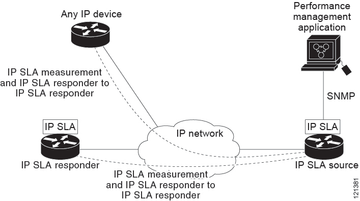
In addition to monitoring jitter, the IP SLA UDP jitter operation can be used as a multipurpose data gathering operation. 
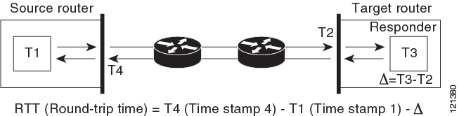
The packets generated by IP SLAs carry sequence information and time stamps from the source and operational target that include packet sending and receiving data. Based on this data, UDP jitter operations measure the following:

  • Per-direction jitter (source to destination and destination to source)

  • Per-direction packet-loss

  • Per-direction delay (one-way delay)

  • Round-trip delay (average round-trip time)

Because the paths for the sending and receiving of data can be different (asymmetric), you can use the per-direction data to more readily identify where congestion or other problems are occurring in the network.

The UDP jitter operation generates synthetic (simulated) UDP traffic and sends a number of UDP packets, each of a specified size, sent a specified number of milliseconds apart, from a source router to a target router, at a given frequency. By default, ten packet-frames, each with a payload size of 10 bytes are generated every 10 ms, and the operation is repeated every 60 seconds. You can configure each of these parameters to best simulate the IP service you want to provide.

To provide accurate one-way delay (latency) measurements, time synchronization (as provided by NTP) is required between the source and the target device. Time synchronization is not required for the one-way jitter and packet loss measurements. If the time is not synchronized between the source and target devices, one-way jitter and packet loss data is returned, but values of 0 are returned for the one-way delay measurements provided by the UDP jitter operation.

How to Configure IP SLAs Operations

This section does not include configuration information for all available operations as the configuration information details are included in the Cisco IOS IP SLAs Configuration Guide. It does include several operations as examples, including configuring the responder, configuring a UDP jitter operation, which requires a responder, and configuring an ICMP echo operation, which does not require a responder. For details about configuring other operations, see the Cisco IOS IP SLAs Configuration Guide.

Default Configuration

No IP SLAs operations are configured.

Configuration Guidelines

For information on the IP SLA commands, see the Cisco IOS IP SLAs Command Reference, Release 12.4T .

For detailed descriptions and configuration procedures, see the Cisco IOS IP SLAs Configuration Guide, Release 12.4TL.

Not all of the IP SLA commands or operations described in the referenced guide are supported on the device. The device supports IP service level analysis by using UDP jitter, UDP echo, HTTP, TCP connect, ICMP echo, ICMP path echo, ICMP path jitter, FTP, DNS, and DHCP, as well as multiple operation scheduling and proactive threshold monitoring. It does not support VoIP service levels using the gatekeeper registration delay operations measurements.

Before configuring any IP SLAs application, you can use the show ip sla application privileged EXEC command to verify that the operation type is supported on your software image. This is an example of the output from the command:


Device# show ip sla application

        IP Service Level Agreements
Version: Round Trip Time MIB 2.2.0, Infrastructure Engine-III

Supported Operation Types:
        icmpEcho, path-echo, path-jitter, udpEcho, tcpConnect, http
        dns, udpJitter, dhcp, ftp, udpApp, wspApp

Supported Features:
        IPSLAs Event Publisher

IP SLAs low memory water mark: 33299323
Estimated system max number of entries: 24389

Estimated number of configurable operations: 24389
Number of Entries configured  : 0
Number of active Entries      : 0
Number of pending Entries     : 0
Number of inactive Entries    : 0
Time of last change in whole IP SLAs: *13:04:37.668 UTC Wed Dec 19 2012

Configuring the IP SLA Responder

The IP SLA responder is available only on Cisco IOS software-based devices, including some Layer 2 devices that do not support full IP SLA functionality.

Follow these steps to configure the IP SLA responder on the target device (the operational target):

Procedure

  Command or Action Purpose

Step 1

enable

Example:

Device> enable

Enables privileged EXEC mode. Enter your password if prompted.

Step 2

configure terminal

Example:

Device# config t 

Enters the global configuration mode.

Step 3

ip sla responder { tcp-connect | udp-echo} ipaddress ip-address port port-number

Example:


Device(config)# ip sla responder udp-echo 172.29.139.134 5000

Configures the device as an IP SLA responder.

The keywords have these meanings:

  • tcp-connect —Enables the responder for TCP connect operations.

  • udp-echo —Enables the responder for User Datagram Protocol (UDP) echo or jitter operations.

  • ipaddress ip-address —Enter the destination IP address.

  • port port-number —Enter the destination port number.

    Note


    The IP address and port number must match those configured on the source device for the IP SLA operation.

Step 4

end

Example:


Device(config)# end

Returns to privileged EXEC mode.

Step 5

end

Example:


Device(config)# end

Returns to privileged EXEC mode.

Step 6

show running-config

Example:


Device# show running-config 

Verifies your entries.

Step 7

copy running-config startup-config

Example:


Device# copy running-config startup-config 

(Optional) Saves your entries in the configuration file.

Implementing IP SLA Network Performance Measurement

Follow these steps to implement IP SLA network performance measurement on your device:

Before you begin

Use the show ip sla application privileged EXEC command to verify that the desired operation type is supported on your software image.

Procedure

  Command or Action Purpose

Step 1

enable

Example:

Device> enable

Enables privileged EXEC mode.

  • Enter your password if prompted.

Step 2

configure terminal

Example:

Device# config t 

Enters the global configuration mode.

Step 3

ip sla operation-number

Example:


Device(config)# ip sla 10

Creates an IP SLA operation, and enters IP SLA configuration mode.

Step 4

udp-jitter {destination-ip-address | destination-hostname} destination-port [source-ip {ip-address | hostname}] [source-port port-number] [control {enable | disable}] [num-packets number-of-packets] [interval interpacket-interval]

Example:


Device(config-ip-sla)# udp-jitter 172.29.139.134 5000 source-ip 172.29.139.140 source-port 4000

Configures the IP SLA operation as the operation type of your choice (a UDP jitter operation is used in the example), and enters its configuration mode (UDP jitter configuration mode is used in the example).

  • destination-ip-address | destination-hostname : Specifies the destination IP address or hostname.

  • destination-port : Specifies the destination port number in the range from 1 to 65535.

  • (Optional) source-ip {ip-address | hostname} : Specifies the source IP address or hostname. When a source IP address or hostname is not specified, IP SLA chooses the IP address nearest to the destination

  • (Optional) source-port port-number : Specifies the source port number in the range from 1 to 65535. When a port number is not specified, IP SLA chooses an available port.

    Note


    If the udp-jitter command does not have the source port configured, UDP chooses any random port for control packets. In case UDP chooses the reserved port 1967, it may result in high CPU utilisation by the IP SLA responder.

  • (Optional) control : Enables or disables sending of IP SLA control messages to the IP SLA responder. By default, IP SLA control messages are sent to the destination device to establish a connection with the IP SLA responder

  • (Optional) num-packets number-of-packets : Enters the number of packets to be generated. The range is 1 to 6000; the default is 10.

  • (Optional) interval inter-packet-interval : Enters the interval between sending packets in milliseconds. The range is 1 to 6000; the default value is 20 ms.

Step 5

frequency seconds

Example:


Device(config-ip-sla-jitter)# frequency 45

(Optional) Configures options for the SLA operation. This example sets the rate at which a specified IP SLA operation repeats. The range is from 1 to 604800 seconds; the default is 60 seconds.

Step 6

threshold milliseconds

Example:


Device(config-ip-sla-jitter)# threshold 200

(Optional) Configures threshold conditions. This example sets the threshold of the specified IP SLA operation to 200. The range is from 0 to 60000 milliseconds.

Step 7

exit

Example:


Device(config-ip-sla-jitter)# exit

Exits the SLA operation configuration mode (UDP jitter configuration mode in this example), and returns to global configuration mode.

Step 8

ip sla schedule operation-number [life {forever | seconds}] [start-time {hh:mm [ :ss] [month day | day month] | pending | now | after hh:mm:ss] [ageout seconds] [recurring]

Example:


Device(config)# ip sla schedule 10 start-time now life forever

Configures the scheduling parameters for an individual IP SLA operation.

  • operation-number : Enter the RTR entry number.

  • (Optional) life : Sets the operation to run indefinitely (forever ) or for a specific number of seconds . The range is from 0 to 2147483647. The default is 3600 seconds (1 hour).

  • (Optional) start-time : Enters the time for the operation to begin collecting information:

    To start at a specific time, enter the hour, minute, second (in 24-hour notation), and day of the month. If no month is entered, the default is the current month.

    Enter pending to select no information collection until a start time is selected.

    Enter now to start the operation immediately.

    Enter after hh:mm:ss to show that the operation should start after the entered time has elapsed.

  • (Optional) ageout seconds : Enter the number of seconds to keep the operation in memory when it is not actively collecting information. The range is 0 to 2073600 seconds, the default is 0 seconds (never ages out).

  • (Optional) recurring : Set the operation to automatically run every day.

Step 9

end

Example:


Device(config)# end

Returns to privileged EXEC mode.

Step 10

show running-config

Example:


Device# show running-config 

Verifies your entries.

Step 11

copy running-config startup-config

Example:


Device# copy running-config startup-config 

(Optional) Saves your entries in the configuration file.

UDP Jitter Configuration

This example shows how to configure a UDP jitter IP SLA operation:


Device(config)# ip sla 10
Device(config-ip-sla)# udp-jitter 172.29.139.134 5000 source-ip 172.29.139.140 source-port 4000
Device(config-ip-sla-jitter)# frequency 30
Device(config-ip-sla-jitter)# exit
Device(config)# ip sla schedule 10 start-time now life forever
Device(config)# end
Device# show ip sla configuration 10
IP SLAs, Infrastructure Engine-II.

Entry number: 10
Owner:
Tag:
Type of operation to perform: udp-jitter
Target address/Source address: 1.1.1.1/0.0.0.0
Target port/Source port: 2/0
Request size (ARR data portion): 32
Operation timeout (milliseconds): 5000
Packet Interval (milliseconds)/Number of packets: 20/10
Type Of Service parameters: 0x0
Verify data: No
Vrf Name:
Control Packets: enabled
Schedule:
    Operation frequency (seconds): 30
    Next Scheduled Start Time: Pending trigger
    Group Scheduled : FALSE
    Randomly Scheduled : FALSE
    Life (seconds): 3600
    Entry Ageout (seconds): never
    Recurring (Starting Everyday): FALSE
    Status of entry (SNMP RowStatus): notInService
Threshold (milliseconds): 5000
Distribution Statistics:
    Number of statistic hours kept: 2
    Number of statistic distribution buckets kept: 1
    Statistic distribution interval (milliseconds): 20
Enhanced History:

Analyzing IP Service Levels by Using the UDP Jitter Operation

Follow these steps to configure a UDP jitter operation on the source device:

Before you begin

You must enable the IP SLA responder on the target device (the operational target) to configure a UDP jitter operation on the source device.

Procedure

  Command or Action Purpose

Step 1

enable

Example:

Device> enable

Enables privileged EXEC mode.

  • Enter your password if prompted.

Step 2

configure terminal

Example:

Device# config t 

Enters the global configuration mode.

Step 3

ip sla operation-number

Example:


Device(config)# ip sla 10

Creates an IP SLA operation, and enters IP SLA configuration mode.

Step 4

udp-jitter {destination-ip-address | destination-hostname} destination-port [source-ip {ip-address | hostname}] [source-port port-number] [control {enable | disable}] [num-packets number-of-packets] [interval interpacket-interval]

Example:


Device(config-ip-sla)# udp-jitter 172.29.139.134 5000 source-ip 172.29.139.140 source-port 4000

Configures the IP SLA operation as a UDP jitter operation, and enters UDP jitter configuration mode.

  • destination-ip-address | destination-hostname : Specifies the destination IP address or hostname.

  • destination-port : Specifies the destination port number in the range from 1 to 65535.

  • (Optional) source-ip {ip-address | hostname} : Specifies the source IP address or hostname. When a source IP address or hostname is not specified, IP SLA chooses the IP address nearest to the destination.

  • (Optional) source-port port-number : Specifies the source port number in the range from 1 to 65535. When a port number is not specified, IP SLA chooses an available port.

    Note


    If the udp-jitter command does not have the source port configured, UDP chooses any random port for control packets. In case UDP chooses the reserved port 1967, it may result in high CPU utilisation by the IP SLA responder.

  • (Optional) control : Enables or disables sending of IP SLA control messages to the IP SLA responder. By default, IP SLA control messages are sent to the destination device to establish a connection with the IP SLA responder.

  • (Optional) num-packets number-of-packets : Enters the number of packets to be generated. The range is 1 to 6000; the default is 10.

  • (Optional) interval inter-packet-interval : Enters the interval between sending packets in milliseconds. The range is 1 to 6000; the default value is 20 ms.

Step 5

frequency seconds

Example:


Device(config-ip-sla-jitter)# frequency 45

(Optional) Sets the rate at which a specified IP SLA operation repeats. The range is from 1 to 604800 seconds; the default is 60 seconds.

Step 6

exit

Example:


Device(config-ip-sla-jitter)# exit

Exits UDP jitter configuration mode, and returns to global configuration mode.

Step 7

ip sla schedule operation-number [life {forever | seconds}] [start-time {hh:mm [ :ss] [month day | day month] | pending | now | after hh:mm:ss] [ageout seconds] [recurring]

Example:


Device(config)# ip sla schedule 10 start-time now life forever

Configures the scheduling parameters for an individual IP SLA operation.

  • operation-number : Enter the RTR entry number.

  • (Optional) life : Sets the operation to run indefinitely (forever ) or for a specific number of seconds . The range is from 0 to 2147483647. The default is 3600 seconds (1 hour).

  • (Optional) start-time : Enters the time for the operation to begin collecting information:

    To start at a specific time, enter the hour, minute, second (in 24-hour notation), and day of the month. If no month is entered, the default is the current month.

    Enter pending to select no information collection until a start time is selected.

    Enter now to start the operation immediately.

    Enter after hh:mm:ss to show that the operation should start after the entered time has elapsed.

  • (Optional) ageout seconds : Enter the number of seconds to keep the operation in memory when it is not actively collecting information. The range is 0 to 2073600 seconds, the default is 0 seconds (never ages out).

  • (Optional) recurring : Set the operation to automatically run every day.

Step 8

end

Example:


Device(config)# end

Returns to privileged EXEC mode.

Step 9

show running-config

Example:


Device# show running-config 

Verifies your entries.

Step 10

copy running-config startup-config

Example:


Device# copy running-config startup-config 

(Optional) Saves your entries in the configuration file.

Configuring a UDP Jitter IP SLA Operation

This example shows how to configure a UDP jitter IP SLA operation:


Device(config)# ip sla 10
Device(config-ip-sla)# udp-jitter 172.29.139.134 5000 source-ip 172.29.139.140 source-port 4000
Device(config-ip-sla-jitter)# frequency 30
Device(config-ip-sla-jitter)# exit
Device(config)# ip sla schedule 10 start-time now life forever
Device(config)# end
Device# show ip sla configuration 10
IP SLAs, Infrastructure Engine-II.

Entry number: 10
Owner:
Tag:
Type of operation to perform: udp-jitter
Target address/Source address: 1.1.1.1/0.0.0.0
Target port/Source port: 2/0
Request size (ARR data portion): 32
Operation timeout (milliseconds): 5000
Packet Interval (milliseconds)/Number of packets: 20/10
Type Of Service parameters: 0x0
Verify data: No
Vrf Name:
Control Packets: enabled
Schedule:
    Operation frequency (seconds): 30
    Next Scheduled Start Time: Pending trigger
    Group Scheduled : FALSE
    Randomly Scheduled : FALSE
    Life (seconds): 3600
    Entry Ageout (seconds): never
    Recurring (Starting Everyday): FALSE
    Status of entry (SNMP RowStatus): notInService
Threshold (milliseconds): 5000
Distribution Statistics:
    Number of statistic hours kept: 2
    Number of statistic distribution buckets kept: 1
    Statistic distribution interval (milliseconds): 20
Enhanced History:

Analyzing IP Service Levels by Using the ICMP Echo Operation

Follow these steps to configure an ICMP echo operation on the source device:

Before you begin

This operation does not require the IP SLA responder to be enabled.

Procedure

  Command or Action Purpose

Step 1

enable

Example:

Device> enable

Enables privileged EXEC mode.

  • Enter your password if prompted.

Step 2

configure terminal

Example:

Device# config terminal 

Enters the global configuration mode.

Step 3

ip sla operation-number

Example:


Device(config)# ip sla 10

Creates an IP SLA operation and enters IP SLA configuration mode.

Step 4

icmp-echo {destination-ip-address | destination-hostname} [source-ip {ip-address | hostname} | source-interface interface-id]

Example:


Device(config-ip-sla)# icmp-echo 172.29.139.134

Configures the IP SLA operation as an ICMP Echo operation and enters ICMP echo configuration mode.

  • destination-ip-address | destination-hostname —Specifies the destination IP address or hostname.

  • (Optional) source-ip {ip-address | hostname} —Specifies the source IP address or hostname. When a source IP address or hostname is not specified, IP SLA chooses the IP address nearest to the destination.

  • (Optional) source-interface interface-id —Specifies the source interface for the operation.

Step 5

frequency seconds

Example:


Device(config-ip-sla-echo)# frequency 30

(Optional) Sets the rate at which a specified IP SLA operation repeats. The range is from 1 to 604800 seconds; the default is 60 seconds.

Step 6

exit

Example:


Device(config-ip-sla-echo)# exit

Exits UDP echo configuration mode, and returns to global configuration mode.

Step 7

ip sla schedule operation-number [life {forever | seconds}] [start-time {hh:mm [:ss] [month day | day month] | pending | now | after hh:mm:ss] [ageout seconds] [recurring]

Example:


Device(config)# ip sla schedule 10 start-time now life forever

Configures the scheduling parameters for an individual IP SLA operation.

  • operation-number —Enter the RTR entry number.

  • (Optional) life —Sets the operation to run indefinitely (forever ) or for a specific number of seconds . The range is from 0 to 2147483647. The default is 3600 seconds (1 hour)

  • (Optional) start-time —Enter the time for the operation to begin collecting information:

    To start at a specific time, enter the hour, minute, second (in 24-hour notation), and day of the month. If no month is entered, the default is the current month.

    Enter pending to select no information collection until a start time is selected.

    Enter now to start the operation immediately.

    Enter after hh:mm:ss to indicate that the operation should start after the entered time has elapsed.

  • (Optional) ageout seconds —Enter the number of seconds to keep the operation in memory when it is not actively collecting information. The range is 0 to 2073600 seconds; the default is 0 seconds (never ages out).

  • (Optional) recurring —Sets the operation to automatically run every day.

Step 8

end

Example:


Device(config)# end

Returns to privileged EXEC mode.

Step 9

show running-config

Example:


Device# show running-config 

Verifies your entries.

Step 10

copy running-config startup-config

Example:


Device# copy running-config startup-config 

(Optional) Saves your entries in the configuration file.

Configuring an ICMP Echo IP SLA Operation

This example shows how to configure an ICMP echo IP SLA operation:


Device(config)# ip sla 10
Device(config-ip-sla)# icmp-echo 172.29.139.134 
Device(config-ip-sla-echo)# frequency 30
Device(config-ip-sla-echo)# exit
Device(config)# ip sla schedule 10 start-time now life forever
Device(config)# end
Device# show ip sla configuration 22
IP SLAs, Infrastructure Engine-II.

Entry number: 12
Owner:
Tag:
Type of operation to perform: echo
Target address: 2.2.2.2
Source address: 0.0.0.0
Request size (ARR data portion): 28
Operation timeout (milliseconds): 5000
Type Of Service parameters: 0x0
Verify data: No
Vrf Name:
Schedule:
    Operation frequency (seconds): 60
    Next Scheduled Start Time: Pending trigger
    Group Scheduled : FALSE
    Randomly Scheduled : FALSE
    Life (seconds): 3600
    Entry Ageout (seconds): never
    Recurring (Starting Everyday): FALSE
    Status of entry (SNMP RowStatus): notInService
Threshold (milliseconds): 5000
Distribution Statistics:
    Number of statistic hours kept: 2
    Number of statistic distribution buckets kept: 1
    Statistic distribution interval (milliseconds): 20
History Statistics:
    Number of history Lives kept: 0
    Number of history Buckets kept: 15
    History Filter Type: None
Enhanced History:

Monitoring IP SLA Operations

The following table describes the commands used to display IP SLA operation configurations and results:

Table 1. Monitoring IP SLA Operations

show ip sla application

Displays global information about Cisco IOS IP SLAs.

show ip sla authentication

Displays IP SLA authentication information.

show ip sla configuration [entry-number]

Displays configuration values including all defaults for all IP SLA operations or a specific operation.

show ip sla enhanced-history {collection-statistics | distribution statistics} [entry-number]

Displays enhanced history statistics for collected history buckets or distribution statistics for all IP SLA operations or a specific operation.

show ip sla ethernet-monitor configuration [entry-number]

Displays IP SLA automatic Ethernet configuration.

show ip sla group schedule [schedule-entry-number]

Displays IP SLA group scheduling configuration and details.

show ip sla history [entry-number | full | tabular]

Displays history collected for all IP SLA operations.

show ip sla mpls-lsp-monitor {collection-statistics | configuration | ldp operational-state | scan-queue | summary [entry-number] | neighbors}

Displays MPLS label switched path (LSP) Health Monitor operations.

show ip sla reaction-configuration [entry-number]

Displays the configured proactive threshold monitoring settings for all IP SLA operations or a specific operation.

show ip sla reaction-trigger [entry-number]

Displays the reaction trigger information for all IP SLA operations or a specific operation.

show ip sla responder

Displays information about the IP SLA responder.

show ip sla statistics [entry-number | aggregated | details]

Displays current or aggregated operational status and statistics.

Monitoring IP SLA Operation Examples

The following example shows all IP SLAs by application:

Device# show ip sla application

        IP Service Level Agreements
Version: Round Trip Time MIB 2.2.0, Infrastructure Engine-III

Supported Operation Types:
        icmpEcho, path-echo, path-jitter, udpEcho, tcpConnect, http
        dns, udpJitter, dhcp, ftp, udpApp, wspApp

Supported Features:
        IPSLAs Event Publisher

IP SLAs low memory water mark: 33299323
Estimated system max number of entries: 24389

Estimated number of configurable operations: 24389
Number of Entries configured  : 0
Number of active Entries      : 0
Number of pending Entries     : 0
Number of inactive Entries    : 0
Time of last change in whole IP SLAs: *13:04:37.668 UTC Wed Dec 19 2012

The following example shows all IP SLA distribution statistics:

Device# show ip sla enhanced-history distribution-statistics

Point by point Enhanced History
Entry    = Entry Number
Int      = Aggregation Interval
BucI     = Bucket Index
StartT   = Aggregation Start Time
Pth      = Path index
Hop      = Hop in path index
Comps    = Operations completed
OvrTh    = Operations completed over thresholds
SumCmp   = Sum of RTT (milliseconds)
SumCmp2L = Sum of RTT squared low 32 bits (milliseconds)
SumCmp2H = Sum of RTT squared high 32 bits (milliseconds)
TMax     = RTT maximum (milliseconds)
TMin     = RTT minimum (milliseconds)

Entry Int BucI StartT     Pth Hop Comps OvrTh SumCmp     SumCmp2L   SumCmp2H   T
Max    TMin

Additional References

Related Documents

Related Topic Document Title

Cisco Medianet Metadata Guide

http://www.cisco.com/c/en/us/td/docs/ios-xml/ios/mdata/configuration/15-sy/mdata-15sy-book/metadata-framework.pdf

Cisco Media Services Proxy Configuration Guide

http://www.cisco.com/c/en/us/td/docs/ios-xml/ios/msp/configuration/15-mt/msp-15-mt-book.pdf

Cisco Mediatrace and Cisco Performance Monitor Configuration Guide

http://www.cisco.com/c/en/us/td/docs/ios-xml/ios/media_monitoring/configuration/15-mt/mm-15-mt-book/mm-mediatrace.html

Error Message Decoder

Description Link

To help you research and resolve system error messages in this release, use the Error Message Decoder tool.

https://www.cisco.com/cgi-bin/Support/Errordecoder/index.cgi

MIBs

MIB MIBs Link

All supported MIBs for this release.

To locate and download MIBs for selected platforms, Cisco IOS releases, and feature sets, use Cisco MIB Locator found at the following URL:

http://www.cisco.com/go/mibs

Technical Assistance

Description Link

The Cisco Support website provides extensive online resources, including documentation and tools for troubleshooting and resolving technical issues with Cisco products and technologies.

To receive security and technical information about your products, you can subscribe to various services, such as the Product Alert Tool (accessed from Field Notices), the Cisco Technical Services Newsletter, and Really Simple Syndication (RSS) Feeds.

Access to most tools on the Cisco Support website requires a Cisco.com user ID and password.

http://www.cisco.com/support

Feature History for Service Level Agreements

This table provides release and related information for the features explained in this module.

These features are available in all the releases subsequent to the one they were introduced in, unless notedotherwise.

Table 2. Feature History for Service Level Agreements

Releases

Feature

Feature Information

Cisco IOS XE Everest 16.5.1a

Service Level Agreements

This feature was introduced.