Information About Generalized Precision Time Protocol
Generalized precision time protocol (PTP) is an IEEE 802.1AS standard that provides a mechanism to synchronize the clocks of the bridges and end-point devices in a network. Generalized PTP defines the mechanism to elect the grandmaster clock (using Best Master Clock Algorithm [BMCA]) among the time-aware bridges and the talker and listener. The grandmaster is the root of the timing hierarchy that gets established in a time-aware network and distributes time to the nodes below to enable synchronization.
Time synchronization also requires determining the link delay and switch delays in the network nodes. A generalized PTP switch is an IEEE 1588 boundary clock, which also determines the link delay using the peer-to-peer delay mechanism. The delays that are computed are included in the correction field of the PTP messages and relayed to the endpoints. The talker and listener use this generalized PTP time as a shared clock reference, which is used to relay and recover the media clock. Generalized PTP currently defines only domain 0, which is what the generalized PTP switch supports.
The peer-to-peer delay mechanism runs on Spanning Tree Protocol-blocked (STP-blocked) ports as well. No other PTP messages are sent over blocked ports.
In a PTP domain, BMCA organizes clocks and ports in an hierarchical fashion, which includes clocks and port states:
Clocks
-
Grandmaster (GM or GMC)
-
Boundary Clock (BC)
Port States
-
Master (M)
-
Slave (S)
-
Passive (P)
Generalized Precision Time Protocol on an EtherChannel Interface
An EtherChannel interface allows multiple physical Ethernet links to be combined into one logical channel. Configuring an EtherChannel interface allows load sharing of traffic among the links in the channel as well as redundancy if one or more links in the EtherChannel fail. This behaviour of an EtherChannel interface does not change when generalized PTP is configured.
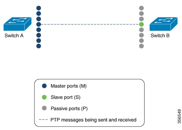
For example, in figure shows that two switches (Switch A and Switch B) are connected through an eight-member EtherChannel. If you consider Switch A as the master clock, all the ports that are a part of the EtherChannel are master ports. Similarly, Switch B is the slave clock, and one of the ports from the EtherChannel bundle becomes the slave port while all the other ports become passive ports. It is always the port with the lowest port number in the EtherChannel bundle that is designated as the slave port. If that slave port is disabled or shut down for any reason, the next port with the lowest port number is designated as the slave port.
The master and slave relationship is established when the feature is configured on an EtherChannel interface as well. The master ports from Switch A send and receive generalized PTP messages. In Switch B, only the slave port exchanges generalized PTP messages. There is no exchange of generalized PTP messages in the passive ports.
 Feedback