Information About MPLS VPN InterAS Options
The MPLS VPN InterAS Options provide various ways of interconnecting VPNs between different MPLS VPN service providers. This allows sites of a customer to exist on several carrier networks (autonomous systems) and have seamless VPN connectivity between these sites.
ASes and ASBRs
An autonomous system (AS) is a single network or group of networks that is controlled by a common system administration group and using a single, clearly defined protocol. In many cases, VPNs extend to different ASes in different geographical areas. Some VPNs must extend across multiple service providers; these VPNs are called overlapping VPNs. The connection between ASes must be seamless to the customer, regardless of the complexity or location of the VPNs.
An AS boundary router (ASBR) is a device in an AS that is configured by using more than one routing protocol, and exchanges routing information with other ASBRs by using an exterior routing protocol (for example, eBGP), or use static routes, or both.
Separate ASes from different service providers communicate by exchanging information in the form of VPN IP addresses and they use the following protocols to share routing information:
-
Within an AS, routing information is shared using iBGP.
iBGP distributes network layer information for IP prefixes within each VPN and each AS.
-
Between ASes, routing information is shared using eBGP.
eBGP allows service providers to set up an interdomain routing system that guarantees loop-free exchange of routing information between separate ASes. The primary function of eBGP is to exchange network reachability information between ASes, including information about the list of AS routes. The ASes use eBGP border edge routers to distribute the routes, which includes label-switching information. Each border edge router rewrites the next-hop and MPLS labels.
MPLS VPN InterAS Options configuration is supported and can include an inter provider VPN, which is MPLS VPNs that include two or more ASes, connected by separate border edge routers. The ASes exchange routes using eBGP, and no iBGP or routing information is exchanged between the ASes.
MPLS VPN InterAS Options
The following options defined in RFC4364 provide MPLS VPN connectivity between different ASes:
-
InterAS Option B – This option provides VPNv4 route distribution between ASBRs.
-
InterAS Option AB – This option combines the best functionality of an interAS option A and interAS option B network to allow an MPLS VPN service provider to interconnect different autonomous systems to provide VPN services.
InterAS Option B

Two methods are supported to distribute the next hop for VPNv4 routes between ASBRs. There is no requirement for LDP or any IGP to be enabled on the link connecting the two ASBRs. The MP-eBGP session between directly connected interfaces on the ASBRs enables the interfaces to forward labeled packets. To ensure this MPLS forwarding for directly connected BGP peers, you must configure mpls bgp forwarding command on the interface connecting to ASBR. This command is implemented in the IOS for directly connected interfaces. Upto 200 BGP neighbors can be configured.
-
Next-hop-self Method: Changing next-hop to that of the local ASBR for all VPNv4 routes learnt from the other ASBR.
-
Redistribute Connected Subnets Method: Redistributing the next hop address of the remote ASBR into the local IGP using redistribute connected subnets command , i.e., the next hop is not changed when the VPNv4 routes are redistributed into the local AS.
 Note |
In case of multiple equal paths - ECMP towards remote AS, you have to configure MPLS static label bindings towards remote Loopback on ASBR. Otherwise, you may experience packet loss. |
The label switch path forwarding sections described below has AS200 configured with the Next-hop-self method and the AS300 is configured with Redistribute-subnet method.
Next-Hop Self Method
The following figure shows the label forwarding path for next-hop-self method. The labels get pushed, swapped and popped on the stack as packet makes its way from PE-200 in AS 200 to PE-300 in AS 300. In step 5, ASBR-A300 receives labeled frame, replaces label 164 with label 161 pushes IGP label 162 onto the label stack.

Redistribute Connected Subnet Method
The following figure shows the label forwarding path for Redistribute connected subnets method. The labels get pushed, swapped and popped on the stack as packet travels from PE- 300 in AS 300 to PE-200 in AS 200. In step 5, ASBR-A200 receives frame with BGP label 20, swaps it with label 29 and pushes label 17.

InterAS Option AB
MPLS VPN service providers need to interconnect different autonomous systems to provide service for multiple VPN customers. The MPLS VPN InterAS Option AB feature allows the different autonomous systems to interconnect by using a single MP-BGP session in the global routing table to carry control plane traffic. This MP-BGP session signals VPN prefixes between two ASBRs for each VRF instance. This traffic can either be IP or MPLS.
MPLS BGP forwarding or LDP does not have to be configured between the two ASBRs as the VPN traffic sent is IP traffic over a VRF specific interface.
The interAS option AB feature provides the following benefits for service providers:
-
IP QoS functions between ASBR peers are maintained for customer SLAs.
-
Dataplane traffic is isolated on a per-VRF basis for security purposes.
-
A dedicated QoS policy can be applied on each VRF by attaching the policy on an SVI.
Route Distribution and Packet Forwarding
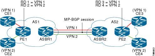
The following attributes describe the topology of the sample interAS Option AB network shown in the figure above:
-
CE1 and CE3 belong to VPN 1.
-
CE2 and CE 4 belong to VPN 2.
-
PE1 uses route distinguisher 1 (RD 1) for VPN 1 (VRF 1) and RD 2 for VPN 2 (VRF 2).
-
PE2 uses RD 3 for VPN 1 (VRF 1) and RD 4 for VPN 2 (VRF 2).
-
ASBR1 has VRF 1 provisioned with RD 5 and VRF 2 provisioned with RD 6.
-
ASBR2 has VRF 1 provisioned with RD 7 and VRF 2 provisioned and RD 8.
-
ASBR1 and ASBR2 have three links between them:
-
VRF 1
-
VRF 2
-
MP-BGP session
-
Route Distribution for VPN 1
A route distinguisher (RD) is an identifier attached to a route that identifies which VPN belongs to each route. Each routing instance must have a unique RD autonomous system associated with it. The RD is used to place a boundary around a VPN so that the same IP address prefixes can be used in different VPNs without having these IP address prefixes overlap. An RD statement is required if the instance type is a VRF.
The following process describes the route distribution process for VPN 1 in the figure above. Prefix “N” is used in this process to indicate the IP address of a VPN.
ASBR 1
-
CE1 advertises the prefix N to PE1.
-
PE1 advertises a VPN prefix RD 1:N to ASBR1 through MP-iBGP.
-
ASBR1 imports the prefix into VPN 1 and creates a prefix RD 5:N.
-
ASBR1 advertises the imported prefix RD 5:N to ASBR2. ASBR1 sets itself as the next hop for prefix RD 5:N and allocates a local label that is signaled with this prefix.
-
ASBR1 advertises the route with the export RT configured on the VRF rather than the originally received RTs. By default, ASBR1 does not advertise the source prefix RD 1:N to ASBR2. This advertisement is suppressed because the prefix is being imported into an Option AB VRF.
ASBR 2
-
ASBR2 receives the prefix RD 5:N and imports it into VPN 1 as RD 7:N.
-
ASBR2 advertises the route with the export RT configured on the VRF rather than the originally received RTs.
-
While importing the prefix, ASBR2 sets the next hop of RD 7:N to the ASBR1 interface IP address in VRF 1. The next hop table ID is also set to VRF 1. When installing the MPLS forwarding entry for RD 7:N, by default ASBR2 does not install the outgoing label in the forwarding process. This enables the traffic between the ASBRs to be IP.
-
ASBR2 advertises the imported prefix RD 7:N to PE2. It sets itself as the next hop for this prefix and also allocates a local label that is signalled with the prefix. By default, ASBR2 does not advertise the source prefix RD 5:N to PE2. This advertisement is suppressed because the prefix is being imported into an Option AB VRF.
-
PE2 imports the RD 7:N into VRF 1 as RD 3:N.
Packet Forwarding for VPN 1
The following packet forwarding process works the same as it does in an Option A scenario. The ASBR acts like the PE by terminating the VPN and then forwards its traffic as standard IP packets with no VPN label to the next PE, which in turn repeats the VPN process. Each PE device, therefore, treats the adjacent PE device as a CE device, and the standard Layer 3 MPLS VPN mechanisms are used for route redistribution with each autonomous system; that is, the PEs use external BGP (eBGP) to distribute unlabeled IPv4 addresses to each other.
-
CE3 sends a packet destined for N to PE2.
-
PE2 encapsulates the packet with the VPN label allocated by ASBR2 and the Interior Gateway Protocol (IGP) label needed to tunnel the packet to ASBR2.
-
The packet arrives on ASBR2 with the VPN label. ASBR2 removes the VPN label and sends the packet as IP to ASBR1 on the VRF 1 interface.
-
The IP packet arrives at ASBR1 on the VRF 1 interface. ASBR1 then encapsulates the packet with the VPN label allocated by PE1 and the IGP label needed to tunnel the packet to PE1.
-
The packet arrives on PE1 with the VPN label. PE1 disposes the VPN label and forwards the IP packet to CE1.
Route Distribution for VPN 2
The following information describes the route distribution process for VPN 2 in the figure above:
ASBR 1
-
CE2 advertises prefix N to PE1, where N is the VPN IP address.
-
PE1 advertises a VPN prefix RD 2:N to ASBR1 through MP-iBGP.
-
ASBR1 imports the prefix into VPN 2 and creates a prefix RD 6:N.
-
ASBR1 advertises the imported prefix RD 6:N to ASBR2. It sets itself as the next hop for this prefix and also allocates a local label that is signalled with the prefix. By default, ASBR1 does not advertise the source prefix RD 2:N to ASBR2. This advertisement is suppressed as the prefix is being imported into an Option AB VRF.
ASBR 2
-
ASBR2 receives the prefix RD 6:N and imports it into VPN 2 as RD 8:N.
-
While importing the prefix, ASBR2 sets the next hop of RD 8:N to ASBR1s interface address in VRF 2. The next hop table ID is also set to that of VRF 2. While installing the MPLS forwarding entry for RD 8:N, by default ASBR2 does not install the outgoing label in the forwarding process. This enables traffic between the ASBRs to be IP.
-
ASBR2 advertises the imported prefix RD 8:N to PE2. It sets itself as the next hop for this prefix and also allocates a local label that is signalled with the prefix. By default, ASBR2 does not advertise the source prefix RD 6:N to PE2. This advertisement is suppressed because the prefix is being imported into an Option AB VRF.
-
PE2 imports the RD 8:N into VRF 2 as RD 4:N.
 Feedback