Restrictions for Generalized Precision Time Protocol over Layer 3 Unicast
Generalized Precision Time Protocol over Layer 3 Unicast feature is not supported on stacked devices.
The documentation set for this product strives to use bias-free language. For the purposes of this documentation set, bias-free is defined as language that does not imply discrimination based on age, disability, gender, racial identity, ethnic identity, sexual orientation, socioeconomic status, and intersectionality. Exceptions may be present in the documentation due to language that is hardcoded in the user interfaces of the product software, language used based on RFP documentation, or language that is used by a referenced third-party product. Learn more about how Cisco is using Inclusive Language.
Generalized Precision Time Protocol over Layer 3 Unicast feature is not supported on stacked devices.
Generalized precision time protocol (PTP) is an IEEE 802.1AS standard that provides a mechanism to synchronize the clocks of the bridges and end-point devices in a network. Generalized PTP defines the mechanism to elect the grandmaster clock (using Best Master Clock Algorithm [BMCA]) among the time-aware bridges and the talker and listener. The grandmaster is the root of the timing hierarchy that gets established in a time-aware network and distributes time to the nodes below to enable synchronization.
Time synchronization also requires determining the link delay and switch delays in the network nodes. A generalized PTP switch is an IEEE 1588 boundary clock, which also determines the link delay using the peer-to-peer delay mechanism. The delays that are computed are included in the correction field of the PTP messages and relayed to the endpoints. The talker and listener use this generalized PTP time as a shared clock reference, which is used to relay and recover the media clock. Generalized PTP currently defines only domain 0, which is what the generalized PTP switch supports.
The peer-to-peer delay mechanism runs on Spanning Tree Protocol-blocked (STP-blocked) ports as well. No other PTP messages are sent over blocked ports.
In a PTP domain, BMCA organizes clocks and ports in an hierarchical fashion, which includes clocks and port states:
Clocks
Grandmaster (GM or GMC)
Boundary Clock (BC)
Port States
Master (M)
Slave (S)
Passive (P)
An EtherChannel interface allows multiple physical Ethernet links to be combined into one logical channel. Configuring an EtherChannel interface allows load sharing of traffic among the links in the channel as well as redundancy if one or more links in the EtherChannel fail. This behaviour of an EtherChannel interface does not change when generalized PTP is configured.
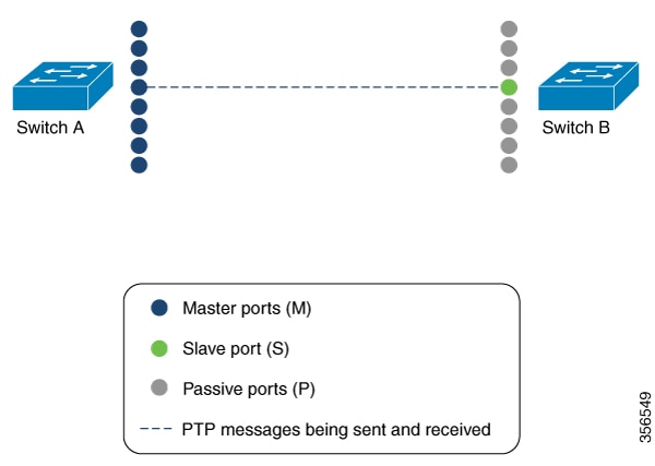
For example, in figure shows that two switches (Switch A and Switch B) are connected through an eight-member EtherChannel. If you consider Switch A as the master clock, all the ports that are a part of the EtherChannel are master ports. Similarly, Switch B is the slave clock, and one of the ports from the EtherChannel bundle becomes the slave port while all the other ports become passive ports. It is always the port with the lowest port number in the EtherChannel bundle that is designated as the slave port. If that slave port is disabled or shut down for any reason, the next port with the lowest port number is designated as the slave port.
The master and slave relationship is established when the feature is configured on an EtherChannel interface as well. The master ports from Switch A send and receive generalized PTP messages. In Switch B, only the slave port exchanges generalized PTP messages. There is no exchange of generalized PTP messages in the passive ports.
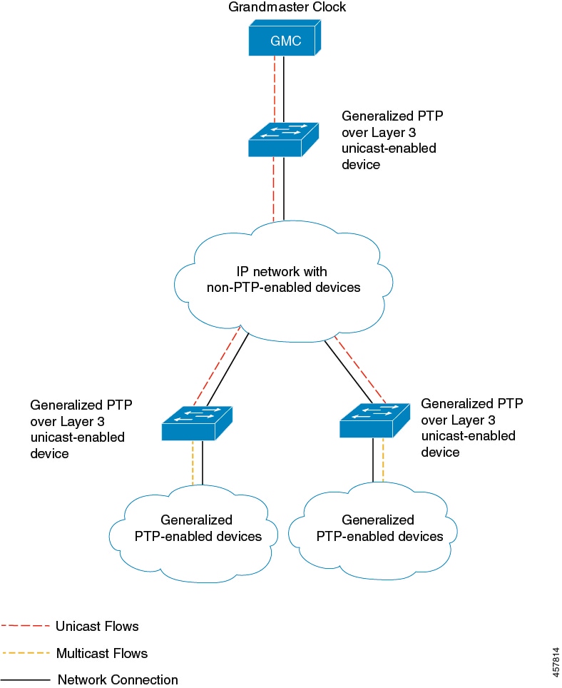
A generalized PTP network consists of Layer 2 devices that are connected to a grandmaster clock that is usually a high-precision clock such as GPS. But for generalized PTP networks that span across multiple floors or even across multiple buildings, configuring a high-precision grandmaster clock on each floor or building increases the cost of deployment. Also, such networks are connected over Layer 3 devices; all Layer 3 devices do not support generalized PTP and certain Layer 3 devices do not support multicast routing.
The Generalized Precision Time Protocol over Layer 3 Unicast feature is a solution introduced to support generalized PTP networks connected over Layer 3 devices. Layer 3 devices, such as the Cisco Catalyst 9500 Series Switches, are configured with this feature. A high-precision grandmaster clock is connected to the primary device that is enabled with this feature. Layer 3 devices that are enabled with this feature synchronize their clocks using PTP boundary clock's end-to-end delay mechanism messages. They also synchronize all the clocks in the generalized PTP networks that are connected to them.
The following figure displays a network, with generalized PTP over Layer 3 unicast configured:
This section describes the various configurations available for generalized PTP.
To enable generalized PTP on a device, perform this procedure.
| Command or Action | Purpose | |
|---|---|---|
|
Step 1 |
enable Example: |
Enables privileged EXEC mode. Enter your password, if prompted. |
|
Step 2 |
configure terminal Example: |
Enters global configuration mode. |
|
Step 3 |
[no]ptp profile dot1as Example: |
Generalized PTP is enabled globally. Use the no form of this command to disable generalized PTP globally. |
|
Step 4 |
end Example: |
Returns to privileged EXEC mode. |
To enable generalized PTP on an interface, perform this procedure.
| Command or Action | Purpose | |
|---|---|---|
|
Step 1 |
enable Example: |
Enables privileged EXEC mode. Enter your password, if prompted. |
|
Step 2 |
configure terminal Example: |
Enters global configuration mode. |
|
Step 3 |
interface interface-id Example: |
Defines the interface to be configured as a trunk, and enters interface configuration mode. The interface that you specify can be a part of an EtherChannel. |
|
Step 4 |
ptp enable Example: |
Enables generalized PTP on all the interfaces. |
|
Step 5 |
end Example: |
Returns to privileged EXEC mode. |
Follow these steps to configure the values of PTP clocks, priority1 and priority2:
| Command or Action | Purpose | |||
|---|---|---|---|---|
|
Step 1 |
enable Example: |
Enables privileged EXEC mode. Enter your password, if prompted. |
||
|
Step 2 |
configure terminal Example: |
Enters global configuration mode. |
||
|
Step 3 |
ptp priority1 value Example: |
Sets the value of PTP clock priority1. The range is from 0 to 255. The default value is 128.
|
||
|
Step 4 |
ptp priority2 value Example: |
Sets the value of PTP clock priority2. The range is from 0 to 255. The default value is 128. |
||
|
Step 5 |
exit Example: |
Returns to global configuration mode. |
To configure generalized PTP over Layer 3 unicast, perform this procedure.
 Note |
You can configure more than one IPv4 unicast connection that connects to a different boundary clock under the same property name. |
| Command or Action | Purpose | |
|---|---|---|
|
Step 1 |
enable Example: |
Enables privileged EXEC mode. Enter your password, if prompted. |
|
Step 2 |
configure terminal Example: |
Enters global configuration mode. |
|
Step 3 |
ptp property word Example: |
Sets the PTP property name and enters property configuration mode. |
|
Step 4 |
transport unicast ipv4 local loopback value Example: |
Configures a unicast IPv4 connection from a loopback interface and enters property transport sub-config mode. value : Loopback interface number. The maximum number of sessions that are supported is 127. |
|
Step 5 |
peer {ip ip_address |vrf word ip ip_address} Example: |
Connects to a peer PTP-aware device.
|
|
Step 6 |
source ip interface interface_id Example: |
(Optional) Configures the source IP address instead of the loopback interface ID. interface_id : Source IP address. |
|
Step 7 |
exit Example: |
Exits property transport sub-config mode and returns to property mode. |
|
Step 8 |
exit Example: |
Exits property mode and returns to global configuration mode. |
|
Step 9 |
ptp dot1as extend property word Example: |
Enables IEEE 802.1AS profile extending on the configured PTP property name. |
Use the following commands in privileged EXEC mode to monitor generalized PTP.
|
Command |
Purpose |
|---|---|
|
show ptp brief |
Displays the brief status of PTP on all interfaces. |
|
show ptp clock |
Displays PTP clock information. |
|
show ptp parent |
Displays the parent clock information. |
|
show ptp port |
Displays the PTP port information. |
|
show platform software fed switch active ptp if-id {interface-id} |
Displays details about the PTP status on a port. |
Use the following commands in privileged EXEC mode to verify generalized PTP over Layer 3 unicast configurations.
|
Command |
Purpose |
|---|---|
|
show ptp transport properties |
Displays the PTP profile and properties, including the transport method, loopback interface number, and PTP state. |
|
show ptp port loopback value |
Displays the PTP configurations of the specified loopback interface. |
|
show platform software fed active ptp interface loopback value |
Displays the PTP connection details and events of the specified loopback interface. |
The following sections provide configuration examples for generalized PTP.
The following is a sample output of the show ptp brief command:
Device# show ptp brief
Interface                       Domain    PTP State
FortyGigabitEthernet1/1/1       0         FAULTY
FortyGigabitEthernet1/1/2       0         SLAVE
GigabitEthernet1/1/1            0         FAULTY
GigabitEthernet1/1/2            0         FAULTY
GigabitEthernet1/1/3            0         FAULTY
GigabitEthernet1/1/4            0         FAULTY
TenGigabitEthernet1/0/1         0         FAULTY
TenGigabitEthernet1/0/2         0         FAULTY
TenGigabitEthernet1/0/3         0         MASTER
TenGigabitEthernet1/0/4         0         FAULTY
TenGigabitEthernet1/0/5         0         FAULTY
TenGigabitEthernet1/0/6         0         FAULTY
TenGigabitEthernet1/0/7         0         MASTER
TenGigabitEthernet1/0/8         0         FAULTY
TenGigabitEthernet1/0/9         0         FAULTY
TenGigabitEthernet1/0/10        0         FAULTY
TenGigabitEthernet1/0/11        0         MASTER
TenGigabitEthernet1/0/12        0         FAULTY
TenGigabitEthernet1/0/13        0         FAULTY
TenGigabitEthernet1/0/14        0         FAULTY
TenGigabitEthernet1/0/15        0         FAULTY
TenGigabitEthernet1/0/16        0         FAULTY
TenGigabitEthernet1/0/17        0         FAULTY
TenGigabitEthernet1/0/18        0         FAULTY
TenGigabitEthernet1/0/19        0         MASTER
TenGigabitEthernet1/0/20        0         FAULTY
TenGigabitEthernet1/0/21        0         FAULTY
TenGigabitEthernet1/0/22        0         FAULTY
TenGigabitEthernet1/0/23        0         FAULTY
TenGigabitEthernet1/0/24        0         FAULTY
TenGigabitEthernet1/1/1         0         FAULTY
TenGigabitEthernet1/1/2         0         FAULTY
TenGigabitEthernet1/1/3         0         FAULTY
TenGigabitEthernet1/1/4         0         FAULTY
TenGigabitEthernet1/1/5         0         FAULTY
TenGigabitEthernet1/1/6         0         FAULTY
TenGigabitEthernet1/1/7         0         FAULTY
TenGigabitEthernet1/1/8         0         FAULTY
The following is a sample output of the show ptp clock command:
Device# show ptp clock
 PTP CLOCK INFO
  PTP Device Type: Boundary clock
  PTP Device Profile: IEEE 802/1AS Profile
  Clock Identity: 0x4:6C:9D:FF:FE:4F:95:0
  Clock Domain: 0
  Number of PTP ports: 38
  PTP Packet priority: 4
  Priority1: 128
  Priority2: 128
  Clock Quality:
        Class: 248
        Accuracy: Unknown
        Offset (log variance): 16640
  Offset From Master(ns): 0
  Mean Path Delay(ns): 0
  Steps Removed: 3
  Local clock time: 00:12:13 UTC Jan 1 1970
The following is a sample output of the show ptp parent command:
Device# show ptp parent
 PTP PARENT PROPERTIES
  Parent Clock:
  Parent Clock Identity: 0xB0:7D:47:FF:FE:9E:B6:80
  Parent Port Number: 3
  Observed Parent Offset (log variance): 16640
  Observed Parent Clock Phase Change Rate: N/A

  Grandmaster Clock:
  Grandmaster Clock Identity: 0x4:6C:9D:FF:FE:67:3A:80
  Grandmaster Clock Quality:
        Class: 248
        Accuracy: Unknown
        Offset (log variance): 16640
        Priority1: 0
        Priority2: 128
The following is a sample output of the show ptp port command:
Device# show ptp port
PTP PORT DATASET: FortyGigabitEthernet1/1/1
  Port identity: clock identity: 0x4:6C:9D:FF:FE:4E:3A:80
  Port identity: port number: 1
  PTP version: 2
  Port state: FAULTY
  Delay request interval(log mean): 5
  Announce receipt time out: 3
  Peer mean path delay(ns): 0
  Announce interval(log mean): 1
  Sync interval(log mean): 0
  Delay Mechanism: End to End
  Peer delay request interval(log mean): 0
  Sync fault limit: 500000000

 PTP PORT DATASET: FortyGigabitEthernet1/1/2
  Port identity: clock identity: 0x4:6C:9D:FF:FE:4E:3A:80
  Port identity: port number: 2
  PTP version: 2
  Port state: FAULTY
  Delay request interval(log mean): 5
  Announce receipt time out: 3
  Peer mean path delay(ns): 0
  Announce interval(log mean): 1
 --More—
The following is a sample output of the show ptp port command for an interface:
Device# show ptp port gi1/0/26
PTP PORT DATASET: GigabitEthernet1/0/26
  Port identity: clock identity: 0x4:6C:9D:FF:FE:4E:3A:80
  Port identity: port number: 28
  PTP version: 2
  Port state: MASTER
  Delay request interval(log mean): 5
  Announce receipt time out: 3
  Peer mean path delay(ns): 0
  Announce interval(log mean): 1
  Sync interval(log mean): 0
  Delay Mechanism: Peer to Peer
  Peer delay request interval(log mean): 0
  Sync fault limit: 500000000
The following is a sample output of the show platform software fed switch active ptp if-id command for an interface:
Device# show platform software fed switch active ptp if-id 0x20
Displaying port data for if_id 20
=======================================

Port Mac Address 04:6C:9D:4E:3A:9A
Port Clock Identity 04:6C:9D:FF:FE:4E:3A:80
Port number 28
PTP Version 2
domain_value 0
dot1as capable: FALSE
sync_recpt_timeout_time_interval 375000000 nanoseconds
sync_interval 125000000 nanoseconds
neighbor_rate_ratio 0.000000
neighbor_prop_delay 0 nanoseconds
compute_neighbor_rate_ratio: TRUE
compute_neighbor_prop_delay: TRUE
port_enabled: TRUE
ptt_port_enabled: TRUE
current_log_pdelay_req_interval 0
pdelay_req_interval 0 nanoseconds
allowed_lost_responses 3
neighbor_prop_delay_threshold 2000 nanoseconds
is_measuring_delay : FALSE
Port state: : MASTER
sync_seq_num 22023
delay_req_seq_num 23857
num sync messages transmitted  0
num sync messages received  0
num followup messages transmitted  0
num followup messages received  0
num pdelay requests transmitted  285695
num pdelay requests received  0
num pdelay responses transmitted  0
num pdelay responses received 0
num pdelay followup responses transmitted  0
num pdelay followup responses received 0The following examples show how to verify generalized PTP on an EtherChannel interface (see Figure).
The following is a sample output of the show ptp brief command used to verify the PTP state on an interface:
Device# show ptp brief | exclude FAULTY
Interface                 Domain     PTP State
TenGigE1/0/39               0         MASTER
TenGigE1/0/44               0         MASTER
TenGigE1/0/48               0         MASTER
The following is a sample output of the show etherchannel summary command used to verify if the interface configured on each port is an EtherChannel interface:
Device# show  etherchannel 1  summary
Flags:  D - down        P - bundled in port-channel
        I - stand-alone s - suspended
        H - Hot-standby (LACP only)
        R - Layer3      S - Layer2
        U - in use      f - failed to allocate aggregator

        M - not in use, minimum links not met
        u - unsuitable for bundling
        w - waiting to be aggregated
        d - default port

        A - formed by Auto LAG
Number of channel-groups in use: 3
Number of aggregators:           3

Group  Port-channel  Protocol    Ports
------+-------------+-----------+-----------------------------------------------
1      Po1(SU)         LACP        Hu1/0/39(P)     Hu1/0/44(P)
                                   Hu1/0/48(P)
The following is a sample output of the show ptp port command used to verify the port state of each interface:
Device# show ptp port tengigabitethernet 1/0/39
PTP PORT DATASET: TenGigE1/0/39
  Port identity: clock identity: 0x0:A7:42:FF:FE:8A:84:C0
  Port identity: port number: 39
  PTP version: 2
  Port state: MASTER
  Delay request interval(log mean): 0
  Announce receipt time out: 3
  Announce interval(log mean): 0
  Sync interval(log mean): 0
  Delay Mechanism: End to End
  Peer delay request interval(log mean): 0
  Sync fault limit: 500000000

Device# show ptp port tengigabitethernet 1/0/44
PTP PORT DATASET: TenGigE1/0/44
  Port identity: clock identity: 0x0:A7:42:FF:FE:8A:84:C0
  Port identity: port number: 44
  PTP version: 2
  Port state: MASTER
  Delay request interval(log mean): 0
  Announce receipt time out: 3
  Announce interval(log mean): 0
  Sync interval(log mean): 0
  Delay Mechanism: End to End
  Peer delay request interval(log mean): 0
  Sync fault limit: 500000000

Device# show ptp port tengigabitethernet 1/0/48
PTP PORT DATASET: TenGigE1/0/48
  Port identity: clock identity: 0x0:A7:42:FF:FE:8A:84:C0
  Port identity: port number: 48
  PTP version: 2
  Port state: MASTER
 Delay request interval(log mean): 0
  Announce receipt time out: 3
  Announce interval(log mean): 0
  Sync interval(log mean): 0
  Delay Mechanism: End to End
  Peer delay request interval(log mean): 0
Sync fault limit: 500000000The following is a sample output of the show ptp brief command used to verify the PTP state on the interfaces:
Device# show ptp brief | exclude FAULTY
Interface                       Domain    PTP State
tenGigE1/0/12                     0         SLAVE
TenGigE1/0/20                     0         PASSIVE
TenGigE1/0/23                     0         PASSIVE
The following is a sample output of the show etherchannel summary command used to verify if the interface configured on each port is an EtherChannel interface:
Device# show etherchannel 1 summary
Flags:  D - down        P - bundled in port-channel
        I - stand-alone s - suspended
        H - Hot-standby (LACP only)
        R - Layer3      S - Layer2
        U - in use      f - failed to allocate aggregator

        M - not in use, minimum links not met
        u - unsuitable for bundling
        w - waiting to be aggregated
        d - default port
        A - formed by Auto LAG


Number of channel-groups in use: 1
Number of aggregators:           1

Group  Port-channel  Protocol    Ports
------+-------------+-----------+-----------------------------------------------
1      Po1(SU)         LACP        Hu1/0/12(P)     Hu1/0/20(P)
                                   Hu1/0/23(P)
The following is a sample output of the show ptp port command used to verify the port state of each interface:
Device# show ptp port tengigabitethernet 1/0/12
PTP PORT DATASET: TenGigE1/0/12
  Port identity: clock identity: 0x0:A7:42:FF:FE:9B:DA:E0
  Port identity: port number: 12
  PTP version: 2
  PTP port number: 12
  PTP slot number: 0
  Port state: SLAVE
  Delay request interval(log mean): 0
  Announce receipt time out: 3
  Announce interval(log mean): 0
  Sync interval(log mean): 0
  Delay Mechanism: End to End
  Peer delay request interval(log mean): 0
  Sync fault limit: 500000000

Device# show ptp port tengigabitethernet 1/0/20
PTP PORT DATASET: TenGigE1/0/20
  Port identity: clock identity: 0x0:A7:42:FF:FE:9B:DA:E0
  Port identity: port number: 20
  PTP version: 2
  PTP port number: 20
  PTP slot number: 0
  Port state: PASSIVE
  Delay request interval(log mean): 0
  Announce receipt time out: 3
  Announce interval(log mean): 0
  Sync interval(log mean): 0
  Delay Mechanism: End to End
  Peer delay request interval(log mean): 0
  Sync fault limit: 500000000

Device# show ptp port tengigabitethernet 1/0/23
PTP PORT DATASET: TenGigE1/0/23
  Port identity: clock identity: 0x0:A7:42:FF:FE:9B:DA:E0
  Port identity: port number: 23
  PTP version: 2
  PTP port number: 23
  PTP slot number: 0
  Port state: PASSIVE
  Delay request interval(log mean): 0
  Announce receipt time out: 3
  Announce interval(log mean): 0
  Sync interval(log mean): 0
  Delay Mechanism: End to End
  Peer delay request interval(log mean): 0
Sync fault limit: 500000000The following examples shows how to configure generalized PTP over Layer 3 unicast on Device 1 and Device 2:
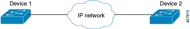
The following example shows how to configure generalized PTP over Layer 3 unicast on Device 1:
Device1> enable
Device1# configure terminal
Device1(config)# interface Loopback0
Device1(config-if)# ip address 192.0.2.1  255.255.255.255
Device1(config-if)# exit
Device1(config)# ptp property gptpproperty
Device1(config-property)# transport unicast ipv4 local Loopback0
Device1(config-property-transport)# peer ip 198.51.100.1
Device1(config-property-transport)# exit
Device1(config-property)# exit
Device1(config)# ptp dot1as extend property gptpproperty
Device1(config)# end
The following example shows how to configure generalized PTP over Layer 3 unicast on Device 2:
Device2> enable
Device2# configure terminal
Device2(config)# interface Loopback0
Device2(config-if)# ip address 198.51.100.1  255.255.255.255
Device2(config-if)# exit
Device2(config)# ptp property gptpproperty
Device2(config-property)# transport unicast ipv4 local Loopback0
Device2(config-property-transport)# peer ip 192.0.2.1
Device2(config-property-transport)# exit
Device2(config-property)# exit
Device2(config)# ptp dot1as extend property gptpproperty
Device2(config)# end
This table provides release and related information for the features explained in this module.
These features are available in all the releases subsequent to the one they were introduced in, unless noted otherwise.
|
Release |
Feature |
Feature Information |
|---|---|---|
|
Cisco IOS XE Fuji 16.8.1a |
Generalized Precision Time Protocol |
Generalized Precision Time Protocol (PTP) is an IEEE 802.1AS standard that provides a mechanism to synchronize the clocks of the bridges and end-point devices in a network. Support for this feature was introduced on all the models of the Cisco Catalyst 9500 Series Switches. |
|
Cisco IOS XE Amsterdam 17.2.1 |
IEEE802.1AS (gPTP) support on EtherChannel Interfaces |
From this release the interface on which you configure generalized PTP can be part of an EtherChannel. Support for this feature was introduced on all the models of the Cisco Catalyst 9500 Series Switches. |
|
Cisco IOS XE Bengaluru 17.5.1 |
Generalized Precision Time Protocol over Layer 3 Unicast |
Generalized PTP over Layer 3 Unicast feature allows message-based synchronization across non-PTP-enabled devices and with unicast PTP configured on Layer 3 devices. |
Use the Cisco Feature Navigator to find information about platform and software image support. To access Cisco Feature Navigator, go to http://www.cisco.com/go/cfn.
 Feedback