Information About Optional Spanning-Tree Features
The following sections provide information about Optional Spanning-Tree features:
PortFast
PortFast immediately brings an interface that is configured as an access or trunk port to the forwarding state from a blocking state, bypassing the listening and learning states.

Interfaces connected to a single workstation or server should not receive bridge protocol data units (BPDUs). An interface with PortFast enabled goes through the normal cycle of spanning-tree status changes when the switch is restarted.
You can enable this feature by enabling it on either the interface or on all nontrunking ports.
Spanning Tree Protocol PortFast Port Types
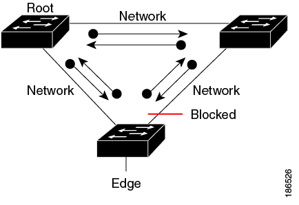
You can configure a spanning tree port (STP) as an edge port, a network port, or a normal port. A port can be in only one of these states at a given time. The default spanning tree port type is normal. You can configure the port type either globally or per interface.
Depending on the type of device to which the interface is connected, you can configure a spanning tree port as one of these port types:
-
A PortFast edge port: It is connected to a Layer 2 host. This can be either an access port or an edge trunk port (portfast edge trunk). This type of port interface immediately transitions to the forwarding state, bypassing the listening and learning states. Use PortFast edge on Layer 2 access ports that are connected to a single workstation or server to allow those devices to connect to the network immediately, rather than waiting for spanning tree to converge.
Even if the interface receives a bridge protocol data unit (BPDU), spanning tree does not place the port into the blocking state. Spanning tree sets the operating state of the port to nonport fast even if the configured state remains port fast edge and starts participating in the topology change.

Note
If you configure a port that is connected to a Layer 2 switch or bridge as an edge port, you might create a bridging loop.
-
A PortFast network port: It is connected only to a Layer 2 switch or bridge.
Bridge Assurance is enabled only on PortFast network ports. For more information, see .
Note
If you configure a port that is connected to a Layer 2 host as a spanning tree network port, the port automatically moves into the blocking state.
-
A PortFast normal port: It is the default type of spanning tree port.
Note
If you enter the spanning-tree portfast trunk command in the global or interface configuration mode, the system automatically saves it as spanning-tree portfast edge trunk .
Bridge Protocol Data Unit Guard
The Bridge Protocol Data Unit (BPDU) guard feature can be globally enabled on the switch or can be enabled per port, but the feature operates with some differences.
When you enable BPDU guard at the global level on PortFast edge-enabled ports, spanning tree shuts down ports that are in a PortFast edge-operational state if any BPDU is received on them. In a valid configuration, PortFast edge-enabled ports do not receive BPDUs. Receiving a BPDU on a PortFast edge-enabled port means an invalid configuration, such as the connection of an unauthorized device, and the BPDU guard feature puts the port in the error-disabled state. When this happens, the switch shuts down the entire port on which the violation occurred.
When you enable BPDU guard at the interface level on any port without also enabling the PortFast edge feature, and the port receives a BPDU, it is put in the error-disabled state.
The BPDU guard feature provides a secure response to invalid configurations because you must manually put the interface back in service. Use the BPDU guard feature in a service-provider network to prevent an access port from participating in the spanning tree.
Bridge Protocol Data Unit Filtering
The BPDU filtering feature can be globally enabled on the switch or can be enabled per interface, but the feature operates with some differences.
Enabling BPDU filtering on PortFast edge-enabled interfaces at the global level keeps those interfaces that are in a PortFast edge-operational state from sending or receiving BPDUs. The interfaces still send a few BPDUs at link-up before the switch begins to filter outbound BPDUs. You should globally enable BPDU filtering on a switch so that hosts that are connected to these interfaces do not receive BPDUs. If a BPDU is received on a PortFast edge-enabled interface, the interface loses its PortFast edge-operational status, and BPDU filtering is disabled.
Enabling BPDU filtering on an interface without also enabling the PortFast edge feature keeps the interface from sending or receiving BPDUs.
 Caution |
Enabling BPDU filtering on an interface is the same as disabling spanning tree on it and can result in spanning-tree loops. |
You can enable the BPDU filtering feature for the entire switch or for an interface.
Bridge Assurance
You can use Bridge Assurance to help prevent looping conditions that are caused by unidirectional links (one-way traffic on a link or port), or a malfunction in a neighboring switch. Here, a malfunction refers to a switch that is not able to run STP any more, while still forwarding traffic (a brain dead switch).
BPDUs are sent out on all operational network ports, including alternate and backup ports, for each hello time period. Bridge Assurance monitors the receipt of BPDUs on point-to-point links on all network ports. When a port does not receive BPDUs within the alloted hello time period, the port is put into a blocked state (the same as a port inconsistent state, which stops forwarding of frames). When the port resumes receipt of BPDUs, the port resumes normal spanning tree operations.
Note |
Only Rapid PVST+ and MST spanning tree protocols support Bridge Assurance. PVST+ does not support Bridge Assurance. |
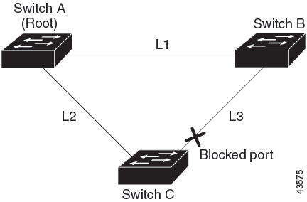
The following example shows how Bridge Assurance protects your network from bridging loops. Here, Network with Normal STP Topology shows a normal STP topology, and Network Loop Due to a Malfunctioning Switch demonstrates a potential network problem when the device fails (brain dead) and Bridge Assurance is not enabled on the network.


Network with STP Topology Running Bridge Assurance shows that the network with Bridge Assurance enabled, and the STP topology progressing normally with bidirectional BDPUs issuing from every STP network port. Network Problem Averted with Bridge Assurance Enabled shows how the potential network problem shown in Network Loop Due to a Malfunctioning Switch does not occur when you have Bridge Assurance enabled on your network.

The system generates syslog messages when a port is blocked or unblocked. The following sample outputs show the log that is generated for each of these states:
Blocked port:
Sep 17 09:48:16.249 PDT: %SPANTREE-2-BRIDGE_ASSURANCE_BLOCK: Bridge
Assurance blocking port GigabitEthernet5/8 on VLAN0200. (stack-dut-R4-4)
Unblocked Port:
Sep 17 09:48:58.426 PDT: %SPANTREE-2-BRIDGE_ASSURANCE_UNBLOCK:
Bridge Assurance unblocking port GigabitEthernet5/8 on VLAN0200. (stack-dut-R4-4)
Guidelines for Configuring Bridge Assurance
Observe these guidelines when configuring Bridge Assurance:
-
Bridge Assurance can be enabled or disabled globally.
-
Bridge Assurance applies to all operational network ports, including alternate and backup ports.
-
Only Rapid PVST+ and MST spanning tree protocols support Bridge Assurance. PVST+ does not support Bridge Assurance.
-
For Bridge Assurance to work properly, it must be supported and configured on both ends of a point-to-point link. If the device on one side of the link has Bridge Assurance enabled and the device on the other side does not, then the connecting port is blocked (a Bridge Assurance inconsistent state). We recommend that you enable Bridge Assurance throughout your network.
-
To enable Bridge Assurance on a port, BPDU filtering and BPDU Guard must be disabled.
-
You can enable Bridge Assurance along with Loop Guard.
-
You can enable Bridge Assurance along with Root Guard. The latter is designed to provide a way to enforce the root bridge placement in the network.
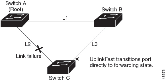
UplinkFast
If a switch loses connectivity, it begins using the alternate paths when the spanning tree selects a new root port. You can accelerate the choice of a new root port when a link or switch fails or when the spanning tree reconfigures itself by enabling UplinkFast. The root port transitions to the forwarding state immediately without going through the listening and learning states, as it would with the normal spanning-tree procedures.
When the spanning tree reconfigures the new root port, other interfaces flood the network with multicast packets, one for each address that was learned on the interface. You can limit these bursts of multicast traffic by reducing the max-update-rate parameter (the default for this parameter is 150 packets per second). However, if you enter zero, station-learning frames are not generated, so the spanning-tree topology converges more slowly after a loss of connectivity.
Note |
UplinkFast is most useful in wiring-closet switches at the access or edge of the network. It is not appropriate for backbone devices. This feature might not be useful for other types of applications. |
UplinkFast provides fast convergence after a direct link failure and achieves load-balancing between redundant Layer 2 links using uplink groups. An uplink group is a set of Layer 2 interfaces (per VLAN), only one of which is forwarding at any given time. Specifically, an uplink group consists of the root port (which is forwarding) and a set of blocked ports, except for self-looping ports. The uplink group provides an alternate path in case the currently forwarding link fails.
Cross-Stack UplinkFast
Cross-Stack UplinkFast (CSUF) provides a fast spanning-tree transition (fast convergence in less than 1 second under normal network conditions) across a switch stack. During the fast transition, an alternate redundant link on the switch stack is placed in the forwarding state without causing temporary spanning-tree loops or loss of connectivity to the backbone. With this feature, you can have a redundant and resilient network in some configurations. CSUF is automatically enabled when you enable the UplinkFast feature.
CSUF might not provide a fast transition all the time; in these cases, the normal spanning-tree transition occurs, completing in 30 to 40 seconds. For more information, see Related Topics.
How Cross-Stack UplinkFast Works
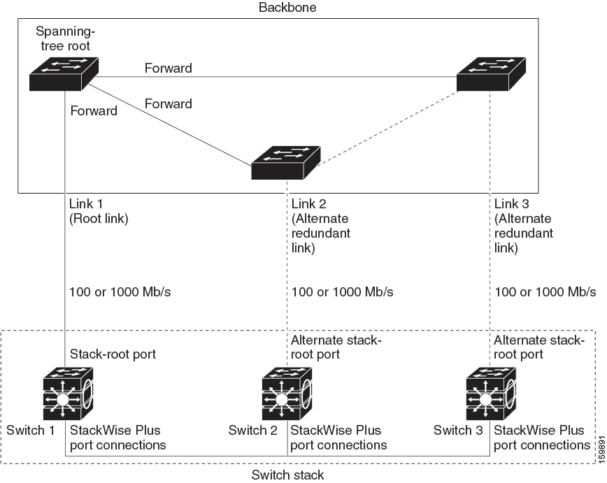
Cross-Stack UplinkFast (CSUF) ensures that one link in the stack is elected as the path to the root.
The stack-root port on Switch 1 provides the path to the root of the spanning tree. The alternate stack-root ports on Switches 2 and 3 can provide an alternate path to the spanning-tree root if the current stack-root switch fails or if its link to the spanning-tree root fails.
Link 1, the root link, is in the spanning-tree forwarding state. Links 2 and 3 are alternate redundant links that are in the spanning-tree blocking state. If Switch 1 fails, if its stack-root port fails, or if Link 1 fails, CSUF selects either the alternate stack-root port on Switch 2 or Switch 3 and puts it into the forwarding state in less than 1 second.
When certain link loss or spanning-tree events occur (described in the following topic), the Fast Uplink Transition Protocol uses the neighbor list to send fast-transition requests to stack members.
The switch sending the fast-transition request needs to do a fast transition to the forwarding state of a port that it has chosen as the root port, and it must obtain an acknowledgment from each stack switch before performing the fast transition.
Each switch in the stack decides if the sending switch is a better choice than itself to be the stack root of this spanning-tree instance by comparing the root, cost, and bridge ID. If the sending switch is the best choice as the stack root, each switch in the stack returns an acknowledgment; otherwise, it sends a fast-transition request. The sending switch then has not received acknowledgments from all stack switches.
When acknowledgments are received from all stack switches, the Fast Uplink Transition Protocol on the sending switch immediately transitions its alternate stack-root port to the forwarding state. If acknowledgments from all stack switches are not obtained by the sending switch, the normal spanning-tree transitions (blocking, listening, learning, and forwarding) take place, and the spanning-tree topology converges at its normal rate (2 * forward-delay time + max-age time).
The Fast Uplink Transition Protocol is implemented on a per-VLAN basis and affects only one spanning-tree instance at a time.
Events That Cause Fast Convergence
Depending on the network event or failure, the CSUF fast convergence might or might not occur.
Fast convergence (less than 1 second under normal network conditions) occurs under these circumstances:
-
The stack-root port link fails.
If two switches in the stack have alternate paths to the root, only one of the switches performs the fast transition.
-
The failed link, which connects the stack root to the spanning-tree root, recovers.
-
A network reconfiguration causes a new stack-root switch to be selected.
-
A network reconfiguration causes a new port on the current stack-root switch to be chosen as the stack-root port.
Note
The fast transition might not occur if multiple events occur simultaneously. For example, if a stack member is powered off, and at the same time, the link connecting the stack root to the spanning-tree root comes back up, the normal spanning-tree convergence occurs.
Normal spanning-tree convergence (30 to 40 seconds) occurs under these conditions:
-
The stack-root switch is powered off, or the software failed.
-
The stack-root switch, which was powered off or failed, is powered on.
-
A new switch, which might become the stack root, is added to the stack.
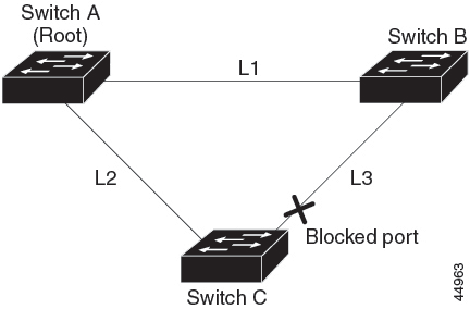
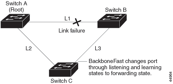
BackboneFast
BackboneFast detects indirect failures in the core of the backbone. BackboneFast is a complementary technology to the UplinkFast feature, which responds to failures on links that are directly connected to access switches. BackboneFast optimizes the maximum-age timer, which controls the amount of time the switch stores protocol information that is received on an interface. When a switch receives an inferior BPDU from the designated port of another switch, the BPDU is a signal that the other switch might have lost its path to the root, and BackboneFast tries to find an alternate path to the root.
BackboneFast starts when a root port or blocked interface on a switch receives inferior BPDUs from its designated switch. An inferior BPDU identifies a switch that declares itself as both the root bridge and the designated switch. When a switch receives an inferior BPDU, it means that a link to which the switch is not directly connected (an indirect link) has failed (that is, the designated switch has lost its connection to the root switch). Under spanning-tree rules, the switch ignores inferior BPDUs for the maximum aging time (default is 20 seconds).
The switch tries to find if it has an alternate path to the root switch. If the inferior BPDU arrives on a blocked interface, the root port and other blocked interfaces on the switch become alternate paths to the root switch. (Self-looped ports are not considered alternate paths to the root switch.) If the inferior BPDU arrives on the root port, all blocked interfaces become alternate paths to the root switch. If the inferior BPDU arrives on the root port and there are no blocked interfaces, the switch assumes that it has lost connectivity to the root switch, causes the maximum aging time on the root port to expire, and becomes the root switch according to normal spanning-tree rules.
If the switch has alternate paths to the root switch, it uses these alternate paths to send a root link query (RLQ) request. The switch sends the RLQ request on all alternate paths to learn if any stack member has an alternate root to the root switch and waits for an RLQ reply from other switches in the network and in the stack. The switch sends the RLQ request on all alternate paths and waits for an RLQ reply from other switches in the network.
When a stack member receives an RLQ reply from a nonstack member on a blocked interface and the reply is destined for another nonstacked switch, it forwards the reply packet, regardless of the spanning-tree interface state.
When a stack member receives an RLQ reply from a nonstack member and the response is destined for the stack, the stack member forwards the reply so that all the other stack members receive it.
If the switch discovers that it still has an alternate path to the root, it expires the maximum aging time on the interface that received the inferior BPDU. If all the alternate paths to the root switch indicate that the switch has lost connectivity to the root switch, the switch expires the maximum aging time on the interface that received the RLQ reply. If one or more alternate paths can still connect to the root switch, the switch makes all interfaces on which it received an inferior BPDU its designated ports and moves them from the blocking state (if they were in the blocking state), through the listening and learning states, and into the forwarding state.
EtherChannel Guard
You can use EtherChannel guard to detect an EtherChannel misconfiguration between the switch and a connected device. A misconfiguration can occur if the switch interfaces are configured in an EtherChannel, but the interfaces on the other device are not. A misconfiguration can also occur if the channel parameters are not the same at both ends of the EtherChannel.
If the switch detects a misconfiguration on the other device, EtherChannel guard places the switch interfaces in the error-disabled state, and displays an error message.
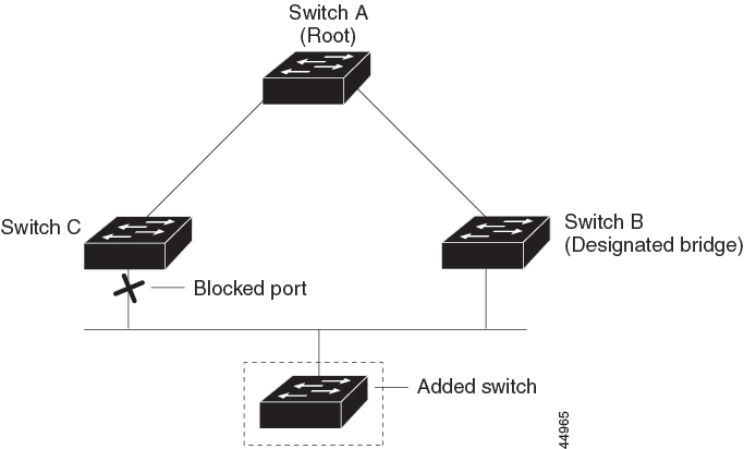
Root Guard
The Layer 2 network of a service provider (SP) can include many connections to switches that are not owned by the SP. In such a topology, the spanning tree can reconfigure itself and select a customer switch as the root switch. You can avoid this situation by enabling root guard on SP switch interfaces that connect to switches in your customer’s network. If spanning-tree calculations cause an interface in the customer network to be selected as the root port, root guard then places the interface in the root-inconsistent (blocked) state to prevent the customer’s switch from becoming the root switch or being in the path to the root.
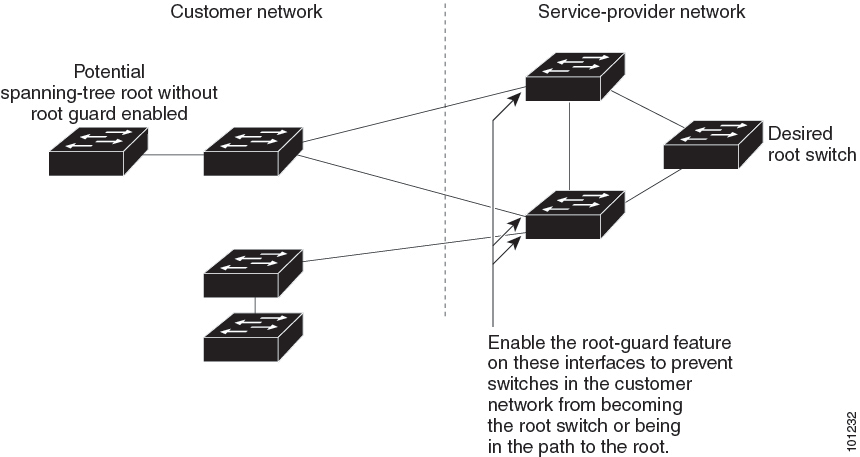
If a switch outside the SP network becomes the root switch, the interface is blocked (root-inconsistent state), and spanning tree selects a new root switch. The customer’s switch does not become the root switch and is not in the path to the root.
If the switch is operating in MST mode, root guard forces the interface to be a designated port. If a boundary port is blocked in an internal spanning-tree (IST) instance because of root guard, the interface also is blocked in all MST instances. A boundary port is an interface that connects to a LAN, the designated switch of which is either an IEEE 802.1D switch or a switch with a different MST region configuration.
Root guard that is enabled on an interface applies to all the VLANs to which the interface belongs. VLANs can be grouped and mapped to an MST instance.
Caution |
Misuse of the root guard feature can cause a loss of connectivity. |
Loop Guard
You can use loop guard to prevent alternate or root ports from becoming designated ports because of a failure that leads to a unidirectional link. This feature is most effective when it is enabled on the entire switched network. Loop guard prevents alternate and root ports from becoming designated ports, and spanning tree does not send BPDUs on root or alternate ports.
When the switch is operating in PVST+ or rapid-PVST+ mode, loop guard prevents alternate and root ports from becoming designated ports, and spanning tree does not send BPDUs on root or alternate ports.
When the switch is operating in MST mode, BPDUs are not sent on nonboundary ports only if the interface is blocked by loop guard in all MST instances. On a boundary port, loop guard blocks the interface in all MST instances.
 Feedback