Configuring VRF-lite

Information About VRF-lite

VRF-lite is a feature that enables a service provider to support two or more VPNs, where IP addresses can be overlapped among the VPNs. VRF-lite uses input interfaces to distinguish routes for different VPNs and forms virtual packet-forwarding tables by associating one or more Layer 3 interfaces with each VRF. Interfaces in a VRF can be either physical, such as Ethernet ports, or logical, such as VLAN SVIs, but a Layer 3 interface cannot belong to more than one VRF at any time.


Note


VRF-lite interfaces must be Layer 3 interfaces.


VRF-lite includes these devices:

  • Customer edge (CE) devices provide customer access to the service provider network over a data link to one or more provider edge routers. The CE device advertises the site’s local routes to the provider edge router and learns the remote VPN routes from it. A Cisco Catalyst Switch can be a CE.

  • Provider routers (or core routers) are any routers in the service provider network that do not attach to CE devices.

With VRF-lite, multiple customers can share one CE, and only one physical link is used between the CE and the PE. The shared CE maintains separate VRF tables for each customer and switches or routes packets for each customer based on its own routing table. VRF-lite extends limited PE functionality to a CE device, giving it the ability to maintain separate VRF tables to extend the privacy and security of a VPN to the branch office.

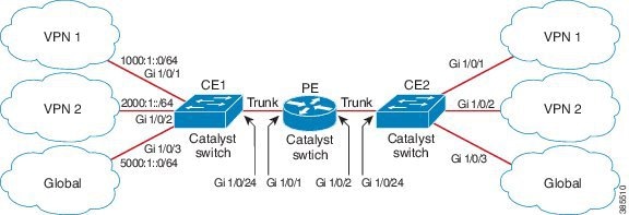
The following figure displays a configuration where each Cisco Catalyst switch acts as multiple virtual CEs. Because VRF-lite is a Layer 3 feature, each interface in a VRF must be a Layer 3 interface.

Figure 1. Cisco Catalyst Switches Acting as Multiple Virtual CEs


This figure illustrates the packet-forwarding process in a VRF-lite CE-enabled network.

  • When the CE receives a packet from a VPN, it looks up the routing table based on the input interface. When a route is found, the CE forwards the packet to the PE.

  • When the ingress PE receives a packet from the CE, it performs a VRF lookup. When a route is found, the router adds a corresponding MPLS label to the packet and sends it to the MPLS network.

  • When an egress PE receives a packet from the network, it strips the label and uses the label to identify the correct VPN routing table. The egress PE then performs the normal route lookup. When a route is found, it forwards the packet to the correct adjacency.

  • When a CE receives a packet from an egress PE, it uses the input interface to look up the correct VPN routing table. If a route is found, the CE forwards the packet within the VPN.

To configure VRF, create a VRF table and specify the Layer 3 interface associated with the VRF. You then configure the routing protocols in the VPN and between the CE and the PE. BGP is the preferred routing protocol used to distribute VPN routing information across the providers’ backbone. The VRF-lite network has three major components:

  • VPN route target communities—Lists all other members of a VPN community. You need to configure VPN route targets for each VPN community member.

  • Multiprotocol BGP peering of VPN community PE routers—Propagates VRF reachability information to all members of a VPN community. You need to configure BGP peering in all PE routers within a VPN community.

  • VPN forwarding—Transports all traffic between all VPN community members across a VPN service-provider network.

Guidelines for Configuring VRF-lite

IPv4 and IPv6

  • A switch with VRF-lite is shared by multiple customers, and all customers have their own routing tables.

  • Because customers use different VRF tables, you can reuse the same IP addresses. Overlapped IP addresses are allowed in different VPNs.

  • VRF-lite lets multiple customers share the same physical link between the PE and the CE. Trunk ports with multiple VLANs separate packets among customers. All customers have their own VLANs.

  • For the PE router, there is no difference between using VRF-lite or using multiple CEs. In Information About VRF-lite, multiple virtual Layer 3 interfaces are connected to the VRF-lite device.

  • The Cisco Catalyst switch supports configuring VRF by using physical ports, VLAN SVIs, or a combination of both. You can connect SVIs through an access port or a trunk port.

  • A customer can use multiple VLANs as long because they do not overlap with those of other customers. A customer’s VLANs are mapped to a specific routing table ID that is used to identify the appropriate routing tables stored on the switch.

  • The Layer 3 TCAM resource is shared between all VRFs. To ensure that any one VRF has sufficient CAM space, use the maximum routes command.

  • A Cisco Catalyst switch using VRF can support one global network and multiple VRFs. The total number of routes supported is limited by the size of the TCAM.

  • A single VRF can be configured for both IPv4 and IPv6.

  • If an incoming packet's destination address is not found in the vrf table, the packet is dropped. Also, if insufficient TCAM space exists for a VRF route, hardware switching for that VRF is disabled and the corresponding data packets are sent to software for processing.

IPv4 Specific

  • You can use most routing protocols (BGP, OSPF, EIGRP, RIP and static routing) between the CE and the PE. However, we recommend using external BGP (EBGP) for these reasons:

    • BGP does not require multiple algorithms to communicate with multiple CEs.

    • BGP is designed for passing routing information between systems run by different administrations.

    • BGP makes simplifies passing attributes of the routes to the CE.

  • The Cisco Catalyst switch supports PIM-SM and PIM-SSM protocols.

  • The capability vrf-lite subcommand under router ospf should be used when configuring OSPF as the routing protocol between the PE and the CE.

IPv6 specific

  • VRF-aware OSPFv3, BGPv6, EIGRPv6, and IPv6 static routing are supported.

  • VRF-aware IPv6 route applications include: ping, telnet, ssh, tftp, ftp and traceroute. (This list does not include the management interface, which is handled differently even though you can configure both IPv4 or IPv6 VRF under it.)

How to Configure VRF-lite

This section provides information about configuring VRF-lite.

Configuring VRF-lite for IPv4

This section provides information about configuring VRF-lite for IPv4.

Configuring VRF-Aware Services

IP services can be configured on global interfaces and within the global routing instance. IP services are enhanced to run on multiple routing instances; they are VRF-aware. Any configured VRF in the system can be specified for a VRF-aware service.

VRF-aware services are implemented in platform-independent modules. VRF provides multiple routing instances in Cisco IOS. Each platform has its own limit on the number of VRFs it supports.

VRF-aware services have the following characteristics:

  • The user can ping a host in a user-specified VRF.

  • ARP entries are learned in separate VRFs. The user can display Address Resolution Protocol (ARP) entries for specific VRFs.

Configuring the User Interface for ARP
Procedure
  Command or Action Purpose

Step 1

show ip arp vrf vrf-name

Example:
Device# show ip arp vrf vrf-name

Displays the ARP table (static and dynamic entries) in the specified VRF.

Step 2

arp vrf vrf-name ip-address mac-address ARPA

Example:
Device(config)# arp vrf vrf-name ip-address mac-address ARPA

Creates a static ARP entry in the specified VRF.

Configuring Per-VRF for TACACS+ Servers

The per-VRF for TACACS+ servers feature enables you to configure per-virtual route forwarding (per-VRF) authentication, authorization, and accounting (AAA) on TACACS+ servers.

You can create the VRF routing table (shown in Steps 3 and 4) and configure the interface (Steps 6, 7, and 8). The actual configuration of per-VRF on a TACACS+ server is done in Steps 10 through 13.

Before you begin

Before configuring per-VRF on a TACACS+ server, you must have configured AAA and a server group.

Procedure
  Command or Action Purpose

Step 1

enable

Example:
Device> enable

Enables privileged EXEC mode. Enter your password if prompted.

Step 2

configure terminal

Example:
Device# configure terminal

Enters global configuration mode.

Step 3

vrf definition vrf-name

Example:
Device(config)# vrf definition vrf-name

Configures a VRF table and enters VRF configuration mode.

Step 4

rd route-distinguisher

Example:
Device(config-vrf)# rd route-distinguisher

Creates routing and forwarding tables for a VRF instance.

Step 5

exit

Example:
Device(config-vrf)# exit

Exits VRF configuration mode.

Step 6

interface interface-name

Example:
Device(config)# interface interface-name

Configures an interface and enters interface configuration mode.

Step 7

vrf forwarding vrf-name

Example:
Device(config-if)# vrf forwarding vrf-name

Configures a VRF for the interface.

Step 8

ip address ip-address mask [secondary]

Example:
Device(config-if)# ip address ip-address mask [secondary]

Sets a primary or secondary IP address for an interface.

Step 9

exit

Example:
Device(config-vrf)# exit

Exits interface configuration mode.

Step 10

aaa group server tacacs+ group-name

Example:
Device(config)# aaa group server tacacs+ tacacs1

Groups different TACACS+ server hosts into distinct lists and distinct methods and enters server-group configuration mode.

Step 11

server-private {ip-address | name} [nat] [single-connection] [port port-number] [timeout seconds] [key [0 | 7] string]

Example:
Device(config-sg-tacacs+)# server-private 10.1.1.1 port 19 key cisco

Configures the IP address of the private TACACS+ server for the group server.

Step 12

vrf forwarding vrf-name

Example:
Device(config-sg-tacacs+)# vrf forwarding vrf-name

Configures the VRF reference of a AAA TACACS+ server group.

Step 13

ip tacacs source-interface subinterface-name

Example:
Device(config-sg-tacacs+)# ip tacacs source-interface subinterface-name

Uses the IP address of a specified interface for all outgoing TACACS+ packets.

Step 14

exit

Example:
Device(config-sg-tacacs)# exit

Exits server-group configuration mode.

Example
The following example lists all the steps to configure per-VRF TACACS+:
Device> enable
Device# configure terminal
Device(config)# vrf definition cisco
Device(config-vrf)# rd 100:1
Device(config-vrf)# exit
Device(config)# interface Loopback0
Device(config-if)# vrf forwarding cisco
Device(config-if)# ip address 10.0.0.2 255.0.0.0
Device(config-if)# exit
Device(config-sg-tacacs+)# vrf forwarding cisco
Device(config-sg-tacacs+)# ip tacacs source-interface Loopback0
Device(config-sg-tacacs)# exit

Configuring Multicast VRFs

SUMMARY STEPS

  1. configure terminal
  2. ip routing
  3. vrf definition vrf-name
  4. ip multicast-routing vrf vrf-name
  5. rd route-distinguisher
  6. route-target {export | import | both} route-target-ext-community
  7. import map route-map
  8. interface interface-id
  9. vrf forwarding vrf-name
  10. ip address ip-address mask
  11. ip pim sparse-mode
  12. end
  13. show vrf definition [brief | detail | interfaces] [vrf-name]
  14. copy running-config startup-config

DETAILED STEPS

  Command or Action Purpose

Step 1

configure terminal

Example:
Device# configure terminal

Enters global configuration mode.

Step 2

ip routing

Example:
Device(config)# ip routing

Enables IP routing.

Step 3

vrf definition vrf-name

Example:
Device(config)# vrf definition vrf-name

Configures a VRF table and enters VRF configuration mode.

Step 4

ip multicast-routing vrf vrf-name

Example:
Device(config-vrf)# ip multicast-routing vrf vrf-name

(Optional) Enables global multicast routing for VRF table.

Step 5

rd route-distinguisher

Example:
Device(config-vrf)# rd route-distinguisher

Creates a VRF table by specifying a route distinguisher. Enter either an AS number and an arbitrary number (xxx:y) or an IP address and arbitrary number (A.B.C.D:y).

Step 6

route-target {export | import | both} route-target-ext-community

Example:
Device(config-vrf)# route-target {export | import | both} route-target-ext-community

Creates a list of import, export, or import and export route target communities for the specified VRF. Enter either an AS system number and an arbitrary number (xxx:y) or an IP address and an arbitrary number (A.B.C.D:y).

The route-target-ext-community value should be the same as the route-distinguisher value entered in Step 4.

Step 7

import map route-map

Example:
Device(config-vrf)# import map route-map

(Optional) Associates a route map with the VRF.

Step 8

interface interface-id

Example:
Device(config)# interface interface-id

Enters interface configuration mode and specifies the Layer 3 interface to be associated with the VRF. The interface can be a routed port or a SVI.

Step 9

vrf forwarding vrf-name

Example:
Device(config-if)# vrf forwarding vrf-name

Associates the VRF with the Layer 3 interface.

Step 10

ip address ip-address mask

Example:
Device(config-if)# ip address ip-address mask

Configures IP address for the Layer 3 interface.

Step 11

ip pim sparse-mode

Example:
Device(config-if)# ip pim sparse-mode

Enables PIM on the VRF-associated Layer 3 interface.

Step 12

end

Example:
Device(config-if)# end

Returns to privileged EXEC mode.

Step 13

show vrf definition [brief | detail | interfaces] [vrf-name]

Example:
Device# show vrf definition brief

Verifies the configuration. Display information about the configured VRFs.

Step 14

copy running-config startup-config

Example:
Device# copy running-config startup-config

(Optional) Saves your entries in the configuration file.

Example

The following example shows how to configure multicast within a VRF table:


Device(config)# ip routing
Device(config)# vrf definition multiVrfA
Device(config-vrf)# ip multicast-routing vrf multiVrfA
Device(config-vrf)# interface GigabitEthernet3/1/0
Device(config-if)# vrf forwarding multiVrfA
Device(config-if)# ip address 172.21.200.203 255.255.255.0
Device(config-if)# ip pim sparse-mode

Configuring IPv4 VRFs

Procedure
  Command or Action Purpose

Step 1

configure terminal

Example:
Device# configure terminal

Enters global configuration mode.

Step 2

ip routing

Example:
Device# configure terminal

Enters global configuration mode.

Step 3

vrf definition vrf-name

Example:
Device(config)# vrf definition vrf-name

Names the VRF and enters VRF configuration mode.

Step 4

rd route-distinguisher

Example:
Device(config-vrf)# rd route-distinguisher

Creates a VRF table by specifying a route distinguisher. Enter either an Autonomous System number number and an arbitrary number (xxx:y) or an IP address and arbitrary number (A.B.C.D:y).

Step 5

route-target {export | import | both} route-target-ext-community

Example:
Device(config-vrf)# route-target {export | import | both} route-target-ext-community

Creates a list of import, export, or import and export route target communities for the specified VRF. Enter either an AS system number and an arbitrary number (xxx:y) or an IP address and an arbitrary number (A.B.C.D:y).

Note


This command is effective only if BGP is running.

Step 6

import map route-map

Example:
Device(config-vrf)# import map route-map

(Optional) Associates a route map with the VRF.

Step 7

interface interface-id

Example:
Device(config-vrf)# interface interface-id

Enters interface configuration mode and specify the Layer 3 interface to be associated with the VRF. The interface can be a routed port or SVI.

Step 8

vrf forwarding vrf-name

Example:
Device(config-if)# vrf forwarding vrf-name

Associates the VRF with the Layer 3 interface.

Step 9

end

Example:
Device(config-if)# end

Returns to privileged EXEC mode.

Step 10

show vrf definition [brief | detail | interfaces] [vrf-name]

Example:
Device# show vfr definition [brief | detail | interfaces] [vrf-name]

Verifies the configuration. Displays information about the configured VRFs.

Step 11

copy running-config startup-config

Example:
Device# copy running-config startup-config

(Optional) Saves your entries in the configuration file.

Use the no vrf definitionvrf-name global configuration command to delete a VRF and to remove all interfaces from it. Use the no vrf forwarding interface configuration command to remove an interface from the VRF.

Configuring VRF-lite for IPv6

This section provides information about configuring VRF-lite for IPv6.

Configuring VRF-Aware Services

IPv6 services can be configured on global interfaces and within the global routing instance. IPv6 services are enhanced to run on multiple routing instances; they are VRF-aware. Any configured VRF in the system can be specified for a VRF-aware service.

VRF-aware services are implemented in platform-independent modules. VRF provides multiple routing instances in Cisco IOS. Each platform has its own limit on the number of VRFs it supports.

VRF-aware services have the following characteristics:

  • The user can ping a host in a user-specified VRF.

  • Neighbor Discovery entries are learned in separate VRFs. The user can display Neighbor Discovery (ND) entries for specific VRFs.

The following services are VRF-aware:

  • Ping

  • Unicast Reverse Path Forwarding (uRPF)

  • Traceroute

  • FTP and TFTP

  • Telnet and SSH

  • NTP

Configuring the User Interface for PING
Perform the following task to configure a VRF-aware ping:
Procedure
Command or Action Purpose

ping vrf vrf-name ipv6-host

Example:
Device# ping vrf vrf-name ipv6-host

Pings an IPv6 host or address in the specified VRF.

Configuring the User Interface for uRPF

You can configure uRPF on an interface assigned to a VRF. Source lookup is performed in the VRF table

SUMMARY STEPS

  1. configure terminal
  2. interface interface-id
  3. no switchport
  4. vrf forwarding vrf-name
  5. ipv6 address ip-address subnet-mask
  6. ipv6 verify unicast source reachable-via rx allow-default
  7. end

DETAILED STEPS

  Command or Action Purpose

Step 1

configure terminal

Example:
Device# configure terminal

Enters global configuration mode.

Step 2

interface interface-id

Example:
Device(config)# interface interface-id

Enters interface configuration mode and specifies the Layer 3 interface to configure.

Step 3

no switchport

Example:
Device(config-if)# no switchport

Removes the interface from Layer 2 configuration mode if it is a physical interface.

Step 4

vrf forwarding vrf-name

Example:
Device(config-if)# vrf forwarding vrf-name

Configures VRF on the interface.

Step 5

ipv6 address ip-address subnet-mask

Example:
Device(config-if)# ip address ip-address mask

Enters the IPv6 address for the interface.

Step 6

ipv6 verify unicast source reachable-via rx allow-default

Example:
Device(config-if)# ipv6 verify unicast source reachable-via 
rx allow-default

Enables uRPF on the interface.

Step 7

end

Example:
Device(config-if)# end

Returns to privileged EXEC mode.

Configuring the User Interface for Traceroute

SUMMARY STEPS

  1. traceroute vrf vrf-name ipv6address

DETAILED STEPS

Command or Action Purpose

traceroute vrf vrf-name ipv6address

Example:
Device# traceroute vrf vrf-name ipv6address

Specifies the name of a VPN VRF in which to find the destination address.

Configuring the User Interface for Telnet and SSH

SUMMARY STEPS

  1. telnet ipv6-address/vrf vrf-name
  2. ssh -l username -vrf vrf-name ipv6-host

DETAILED STEPS

  Command or Action Purpose

Step 1

telnet ipv6-address/vrf vrf-name

Example:
Device# telnet ipv6-address/vrf vrf-name

Connects through Telnet to an IPv6 host or address in the specified VRF.

Step 2

ssh -l username -vrf vrf-name ipv6-host

Example:
Device# ssh -l username -vrf  vrf-name ipv6-host

Connects through SSH to an IPv6 host or address in the specified VRF.

Configuring the User Interface for NTP

SUMMARY STEPS

  1. configure terminal
  2. ntp server vrf vrf-name ipv6-host
  3. ntp peer vrf vrf-name ipv6-host

DETAILED STEPS

  Command or Action Purpose

Step 1

configure terminal

Example:

Device# configure terminal

Enters global configuration mode.

Step 2

ntp server vrf vrf-name ipv6-host

Example:
Device(config)# ntp server vrf vrf-name ipv6-host

Configure the NTP server in the specified VRF.

Step 3

ntp peer vrf vrf-name ipv6-host

Example:
Device(config)# ntp peer vrf vrf-name ipv6-host

Configure the NTP peer in the specified VRF.

Configuring IPv6 VRFs

SUMMARY STEPS

  1. configure terminal
  2. vrf definition vrf-name
  3. rd route-distinguisher
  4. address-family ipv4 | ipv6
  5. route-target {export | import | both} route-target-ext-community
  6. exit-address-family
  7. vrf definition vrf-name
  8. ipv6 multicast multitopology
  9. address-family ipv6 multicast
  10. end

DETAILED STEPS

  Command or Action Purpose

Step 1

configure terminal

Example:
Device# configure terminal

Enters global configuration mode.

Step 2

vrf definition vrf-name

Example:
Device(config)# vrf definition vrf-name

Names the VRF and enters VRF configuration mode.

Step 3

rd route-distinguisher

Example:
Device(config-vrf)# rd route-distinguisher

(Optional) Creates a VRF table by specifying a route distinguisher. Enter either an Autonomous System number and an arbitrary number (xxx:y) or an IP address and arbitrary number (A.B.C.D:y).

Step 4

address-family ipv4 | ipv6

Example:
Device(config-vrf)# address-family ipv4 | ipv6

(Optional) IPv4 by default. Configuration MUST for IPv6.

Step 5

route-target {export | import | both} route-target-ext-community

Example:
Device(config-vrf)# route-target {export | import | both} route-target-ext-community

Creates a list of import, export, or import and export route target communities for the specified VRF. Enter either an AS system number and an arbitrary number (xxx:y) or an IP address and an arbitrary number (A.B.C.D:y).

Note


This command is effective only if BGP is running.

Step 6

exit-address-family

Example:
Device(config-vrf)# exit-address-family

Exits VRF address-family configuration mode and return to VRF configuration mode.

Step 7

vrf definition vrf-name

Example:
Device(config)# vrf definition vrf-name

Enters VRF configuration mode.

Step 8

ipv6 multicast multitopology

Example:
Device(config-vrf-af)# ipv6 multicast multitopology

Enables multicast specific RPF topology.

Step 9

address-family ipv6 multicast

Example:
Device(config-vrf)# address-family ipv6 multicast

Enter multicast IPv6 address-family.

Step 10

end

Example:
Device(config-vrf-af)# end

Returns to privileged EXEC mode.

Example

This example shows how to configure VRFs:


Device(config)#  vrf definition red
Device(config-vrf)# rd 100:1 
Device(config-vrf)# address family ipv6
Device(config-vrf-af)# route-target both 200:1
Device(config-vrf)# exit-address-family
Device(config-vrf)# vrf definition red
Device(config-vrf)# ipv6 multicast multitopology
Device(config-vrf)# address-family ipv6 multicast
Device(config-vrf-af)# end

Associating Interfaces to the Defined VRFs

SUMMARY STEPS

  1. interface interface-id
  2. no switchport
  3. vrf forwarding vrf-name
  4. ipv6 enable
  5. ipv6 address ip-address subnet-mask
  6. show ipv6 vrf [brief | detail | interfaces] [vrf-name]
  7. copy running-config startup-config

DETAILED STEPS

  Command or Action Purpose

Step 1

interface interface-id

Example:
Device(config-vrf)# interface interface-id

Enters interface configuration mode and specify the Layer 3 interface to be associated with the VRF. The interface can be a routed port or SVI.

Step 2

no switchport

Example:
Device(config-if)# no switchport

Removes the interface from configuration mode if it is a physical interface.

Step 3

vrf forwarding vrf-name

Example:
Device(config-if)# vrf forwarding vrf-name

Associates the VRF with the Layer 3 interface.

Step 4

ipv6 enable

Example:
Device(config-if)# ipv6 enable

Enable IPv6 on the interface.

Step 5

ipv6 address ip-address subnet-mask

Example:
Device(config-if)# ipv6 address ip-address subnet-mask

Enters the IPv6 address for the interface.

Step 6

show ipv6 vrf [brief | detail | interfaces] [vrf-name]

Example:
Device# show ipv6 vrf [brief | detail | interfaces] [vrf-name]

Verifies the configuration. Displays information about the configured VRFs.

Step 7

copy running-config startup-config

Example:
Device# copy running-config startup-config

(Optional) Saves your entries in the configuration file.

Example
This example shows how to associate an interface to VRFs:
Switch(config-vrf)# interface ethernet0/1
Switch(config-if)# vrf forwarding red
Switch(config-if)# ipv6 enable
Switch(config-if)# ipv6 address 5000::72B/64

Populate VRF with Routes via Routing Protocols

This section provides information about populating VRF with routes via routing protocols.

Configuring VRF Static Routes

SUMMARY STEPS

  1. configure terminal
  2. ipv6 route [vrf vrf-name] ipv6-prefix/prefix-length {ipv6-address | interface-type interface-number [ipv6-address]}

DETAILED STEPS

  Command or Action Purpose

Step 1

configure terminal

Example:
Device# configure terminal

Enters global configuration mode.

Step 2

ipv6 route [vrf vrf-name] ipv6-prefix/prefix-length {ipv6-address | interface-type interface-number [ipv6-address]}

Example:
Device(config)# ipv6 route [vrf vrf-name] ipv6-prefix/prefix-length {ipv6-address | interface-type interface-number [ipv6-address]}

To configure static routes specific to VRF.

Example
Device(config)# ipv6 route vrf v6a 7000::/64 TenGigabitEthernet32 4000::2
Configuring OSPFv3 Router Process

SUMMARY STEPS

  1. configure terminal
  2. router ospfv3 process-id
  3. area area-ID [default-cot | nssa | stub]
  4. router-id router-id
  5. address-family ipv6 unicast vrf vrf-name
  6. redistribute source-protocol [process-id] options
  7. end

DETAILED STEPS

  Command or Action Purpose

Step 1

configure terminal

Example:
Device# configure terminal

Enters global configuration mode.

Step 2

router ospfv3 process-id

Example:
Device(config)# router ospfv3 process-id

Enables OSPFv3 router configuration mode for the IPv6 address family.

Step 3

area area-ID [default-cot | nssa | stub]

Example:
Device(config-router)# area area-ID [default-cot | nssa | stub]

Configures the OSPFv3 area.

Step 4

router-id router-id

Example:
Device(config-router)# router-id router-id

Use a fixed router ID.

Step 5

address-family ipv6 unicast vrf vrf-name

Example:
Device(config-router)# address-family ipv6 unicast vrf vrf-name

Enters IPv6 address family configuration mode for OSPFv3 in VRF vrf-name

Step 6

redistribute source-protocol [process-id] options

Example:
Device(config-router)# redistribute source-protocol [process-id] options

Redistributes IPv6 routes from one routing domain into another routing domain.

Step 7

end

Example:
Device(config-router)# end

Returns to privileged EXEC mode.

Example
This example shows how configure the OSPFv3 router process:
Device(config-router)# router ospfv3 1
Device(config-router)# router-id 1.1.1.1
Device(config-router)# address-family ipv6 unicast
Device(config-router-af)# exit-address-family
Enabling OSPFv3 on an Interface

SUMMARY STEPS

  1. configure terminal
  2. interface type-number
  3. ospfv3 process-id area area-ID ipv6 [instance instance-id]
  4. end

DETAILED STEPS

  Command or Action Purpose

Step 1

configure terminal

Example:
Device# configure terminal

Enters global configuration mode.

Step 2

interface type-number

Example:
Device(config-vrf)# interface type-number

Specifies an interface type and number, and places the switch in interface configuration mode.

Step 3

ospfv3 process-id area area-ID ipv6 [instance instance-id]

Example:
Device(config-if)# ospfv3 process-id area area-ID ipv6 [instance instance-id]

Enables OSPFv3 on an interface with IPv6 AF.

Step 4

end

Example:
Device(config-if)# end

Returns to privileged EXEC mode.

Example
This example show how to enable OSPFv3 on an interface:
Device(config)# interface GigabitEthernet2/1
Device(config-if)# no switchport
Device(config-if)# ipv6 address 4000::2/64
Device(config-if)# ipv6 enable
Device(config-if)# ipv6 ospf 1 area 0
Device(config-if)# end
Configuring EIGRPv6 Routing Process

SUMMARY STEPS

  1. configure terminal
  2. router eigrp virtual-instance-name
  3. address-family ipv6 vrf vrf-name autonomous-system autonomous-system-number
  4. topology {base | topology-name tid number
  5. exit-aftopology
  6. eigrp router-id ip-address
  7. end

DETAILED STEPS

  Command or Action Purpose

Step 1

configure terminal

Example:
Device# configure terminal

Enters global configuration mode.

Step 2

router eigrp virtual-instance-name

Example:
Device(config)# router eigrp virtual-instance-name

Configures the EIGRP routing process and enters router configuration mode.

Step 3

address-family ipv6 vrf vrf-name autonomous-system autonomous-system-number

Example:
Device(config-router)# address-family ipv6 vrf vrf-name autonomous-system autonomous-system-number

Enables EIGRP IPv6 VRF-Lite and enters address family configuration mode.

Step 4

topology {base | topology-name tid number

Example:
Device(config-router-af)# topology {base | topology-name tid number

Configures an EIGRP process to route IP traffic under the specified topology instance and enters address family topology configuration mode.

Step 5

exit-aftopology

Example:
Device(config-router-af-topology)# exit-aftopology

Exits address family topology configuration mode.

Step 6

eigrp router-id ip-address

Example:
Device(config-router)# eigrp router-id ip-address

Enables the use of a fixed router-id.

Step 7

end

Example:
Device(config-router)# end

Exits router configuration mode.

Example
This example shows how to configure an EIGRP routing process:

Device(config)# router eigrp test
Device(config-router)# address-family ipv6 unicast vrf b1 autonomous-system 10
Device(config-router-af)# topology base
Device(config-router-af-topology)# exit-af-topology
Device(config-router)# eigrp router-id 2.3.4.5
Device(config-router)# exit-address-family

Additional Information for VRF-lite

This section provides additional information about VRF-lite.

VPN Co-existence Between IPv4 and IPv6

Backward compatibility between the “older” CLI for configuring IPv4 and the “new” CLI for IPv6 exists. This means that a configuration might contain both CLI. The IPv4 CLI retains the ability to have on the same interface, an IP address defined within a VRF as well as an IPv6 address defined in the global routing table.

For example:
vrf definition red
 rd 100:1 
 address family ipv6
 route-target both 200:1 
 exit-address-family
!
vrf definition blue
 rd 200:1 
 route-target both 200:1
!
interface Ethernet0/0
 vrf forwarding red
 ip address 50.1.1.2 255.255.255.0
 ipv6 address 4000::72B/64
!
interface Ethernet0/1
 vrf forwarding blue
 ip address 60.1.1.2 255.255.255.0
 ipv6 address 5000::72B/64

In this example, all addresses (v4 and v6) defined for Ethernet0/0 refer to VRF red whereas for Ethernet0/1, the IP address refers to VRF blue but the ipv6 address refers to the global IPv6 routing table.

Verifying VRF-lite Configuration

This section provides steps for verifying VRF-lite configuration.

Displaying IPv4 VRF-lite Status

To display information about VRF-lite configuration and status, perform one of the following tasks:

Command

Purpose

Device# show ip protocols vrf vrf-name 

Displays routing protocol information associated with a VRF.

Device# show ip route vrf vrf-name [connected] [protocol
[as-number]] [list] [mobile] [odr] [profile] [static] [summary][supernets-only] 

Displays IP routing table information associated with a VRF.

Device# show vrf definition [brief | detail | interfaces] [vrf-name]  

Displays information about the defined VRF instances.

Device# bidir vrf instance-name a.b.c.d | active | bidriectional| count | interface | proxy | pruned | sparse | ssm | static | summary 

Displays information about the defined VRF instances.

This example shows how to display multicast route table information within a VRF instance:
Switch# show ip mroute 226.0.0.2 
IP Multicast Routing Table
Flags: S - Sparse, B - Bidir Group, s - SSM Group, C - Connected,
       L - Local, P - Pruned, R - RP-bit set, F - Register flag,
       T - SPT-bit set, J - Join SPT, M - MSDP created entry, E - Extranet,
       X - Proxy Join Timer Running, A - Candidate for MSDP Advertisement,
       U - URD, I - Received Source Specific Host Report,
       Z - Multicast Tunnel, z - MDT-data group sender,
       Y - Joined MDT-data group, y - Sending to MDT-data group,
       G - Received BGP C-Mroute, g - Sent BGP C-Mroute,
       N - Received BGP Shared-Tree Prune, n - BGP C-Mroute suppressed,
       Q - Received BGP S-A Route, q - Sent BGP S-A Route,
       V - RD & Vector, v - Vector, p - PIM Joins on route,
       x - VxLAN group, c - PFP-SA cache created entry
Outgoing interface flags: H - Hardware switched, A - Assert winner, p - PIM Join
Timers: Uptime/Expires
Interface state: Interface, Next-Hop or VCD, State/Mode
 
(*, 226.0.0.2), 00:01:17/stopped, RP 1.11.1.1, flags: SJCF
  Incoming interface: Null, RPF nbr 0.0.0.0
  Outgoing interface list:
    Vlan100, Forward/Sparse, 00:01:17/00:02:36
 
(5.0.0.11, 226.0.0.2), 00:01:17/00:01:42, flags: FT
  Incoming interface: Vlan5, RPF nbr 0.0.0.0
  Outgoing interface list:
    Vlan100, Forward/Sparse, 00:01:17/00:02:36

Configuration Examples for VRF-lite

This section provides configuration examples for VRF-lite.

Configuration Example for IPv6 VRF-lite

The following topology illustrates how to use OSPFv3 for CE-PE routing.

Figure 2. VRF-lite Configuration Example


Configuring CE1 Switch

ipv6 unicast-routing 
vrf definition v1
 rd 100:1
 !
address-family ipv6
 exit-address-family
!

vrf definition v2
 rd 200:1
 !
address-family ipv6
 exit-address-family
!

interface Vlan100
 vrf forwarding v1
 ipv6 address 1000:1::1/64
 ospfv3 100 ipv6 area 0
! 

interface Vlan200
 vrf forwarding v2
 ipv6 address 2000:1::1/64
 ospfv3 200 ipv6 area 0
!         

interface GigabitEthernet 1/0/1
switchport access vlan 100
end

interface GigabitEthernet 1/0/2
switchport access vlan 200
end

interface GigabitEthernet 1/0/24
 switchport trunk encapsulation dot1q

switchport mode trunk
end

router ospfv3 100
 router-id 10.10.10.10
 !
 address-family ipv6 unicast vrf v1
  redistribute connected
  area 0 normal
 exit-address-family
!

router ospfv3 200
 router-id 20.20.20.20
 !
 address-family ipv6 unicast vrf v2
  redistribute connected
  area 0 normal
 exit-address-family
!

Configuring PE Switch

ipv6 unicast-routing 

vrf definition v1
 rd 100:1
 !
address-family ipv6
 exit-address-family
!

vrf definition v2
 rd 200:1
 !
address-family ipv6
 exit-address-family
!
interface Vlan600
 vrf forwarding v1
 no ipv6 address
 ipv6 address 1000:1::2/64
 ospfv3 100 ipv6 area 0
!

interface Vlan700
 vrf forwarding v2
 no ipv6 address
 ipv6 address 2000:1::2/64
 ospfv3 200 ipv6 area 0
!

interface Vlan800
 vrf forwarding v1
 ipv6 address 3000:1::7/64
 ospfv3 100 ipv6 area 0
!
interface Vlan900
 vrf forwarding v2
 ipv6 address 4000:1::7/64
 ospfv3 200 ipv6 area 0
!

interface GigabitEthernet 1/0/1
 switchport trunk encapsulation dot1q
 switchport mode trunk
 exit

interface GigabitEthernet 1/0/2
 switchport trunk encapsulation dot1q

switchport mode trunk
	exit

router ospfv3 100
 router-id 30.30.30.30
 !
 address-family ipv6 unicast vrf v1
  redistribute connected
  area 0 normal
 exit-address-family
	!
address-family ipv6 unicast vrf v2
  redistribute connected
  area 0 normal
 exit-address-family
	!

Configuring CE2 Switch

ipv6 unicast-routing 

vrf definition v1
 rd 100:1
 !
address-family ipv6
 exit-address-family
!

vrf definition v2
 rd 200:1
 !
address-family ipv6
 exit-address-family
!

interface Vlan100
 vrf forwarding v1

ipv6 address 1000:1::3/64
 ospfv3 100 ipv6 area 0
!

interface Vlan200
 vrf forwarding v2
 ipv6 address 2000:1::3/64
 ospfv3 200 ipv6 area 0
!

interface GigabitEthernet 1/0/1
switchport access vlan 100
end

interface GigabitEthernet 1/0/2
switchport access vlan 200
end

interface GigabitEthernet 1/0/24
 switchport trunk encapsulation dot1q
 switchport mode trunk
 end

router ospfv3 100
 router-id 40.40.40.40
 !
 address-family ipv6 unicast vrf v1
  redistribute connected
  area 0 normal
 exit-address-family
!

router ospfv3 200
 router-id 50.50.50.50
 !
 address-family ipv6 unicast vrf v2
  redistribute connected

area 0 normal
 exit-address-family
!

Additional References for VRF-Lite

Related Documents

Related Topic Document Title

For complete syntax and usage information for the commands used in this chapter.

See the IP Multicast Routing Commands section of the Command Reference (Catalyst 9600 Series Switches)

Standards and RFCs

Standard/RFC Title

RFC 6763

DNS-Based Service Discovery

Multicast DNS Internet-Draft

Multicast

Feature History and Information for Multicast VRF-lite

The following table provides release information about the feature or features described in this module. This table lists only the software release that introduced support for a given feature in a given software release train. Unless noted otherwise, subsequent releases of that software release train also support that feature.

Use Cisco Feature Navigator to find information about platform support and Cisco software image support. To access Cisco Feature Navigator, go to www.cisco.com/go/cfn. An account on Cisco.com is not required.

Feature Name

Release

Feature Information

IPv6 Multicast support with VRF-Lite

Cisco IOS XE Everest 16.6.1

IPv6 VRF-Lite allows a service provider to support two or more VPNs with overlapping IP addresses using one interface.