The documentation set for this product strives to use bias-free language. For the purposes of this documentation set, bias-free is defined as language that does not imply discrimination based on age, disability, gender, racial identity, ethnic identity, sexual orientation, socioeconomic status, and intersectionality. Exceptions may be present in the documentation due to language that is hardcoded in the user interfaces of the product software, language used based on RFP documentation, or language that is used by a referenced third-party product. Learn more about how Cisco is using Inclusive Language.
Both switches in the Cisco StackWise Virtual pair must be directly connected to each other.
Both switches in the Cisco StackWise Virtual pair must be of the same switch model.
Both switches in the Cisco StackWise Virtual pair must be running the same license level.
Both switches in the Cisco StackWise Virtual pair must be running the same software version.
Both switches in the Cisco StackWise Virtual pair must be running the same SDM template.
All the ports used for configuring a StackWise Virtual Link (SVL) must share the same speed. For example, you cannot configure
a 10G or a 40G port to form an SVL, simultaneously. Furthermore, all ports used for configuring SVL must be either from the
same line card or across line cards within the same chassis.
Restrictions for Cisco StackWise Virtual
Cisco StackWise Virtual can be configured only on the same supervisor module slot on both the chassis as asymmetric supervisor
module slots between the chassis is not supported. For example, if you have inserted the supervisor module in slot 3 in chassis
1, then chassis 2 should also have the supervisor module in slot 3.
Cisco StackWise Virtual configuration commands will be recognised only on a switch running Network Advantage license.
Only Cisco Transceiver Modules are supported.
When deploying Cisco StackWise Virtual, ensure that VLAN ID 4094 is not used anywhere on the network. All inter-chassis system
control communication between stack members is carried over the reserved VLAN ID 4094 from the global range.
Dual-Active Detection (DAD) and SVL configuration must be performed manually and the devices should be rebooted for the configuration
changes to take effect.
In a Cisco StackWise Virtual solution, QSA along with 10G interfaces can be used as data ports or SVL or DAD links.
In a Cisco StackWise Virtual solution, QSA along with 1G interfaces can be used as data ports or DAD links. SVL links are
not supported on 1G interfaces.
The following are the restrictions for C9600-LC-48TX, C9600-LC-48YL, and C9600-LC-24C line cards:
DAD links are supported only in 1G interfaces, and SVL links are supported on the C9600-LC-48TX line card only with interfaces
that are operating at 10G speed.
DAD links configured between C9600-LC-48TX line card and C9600-LC-48YL line card or C9600-LC-24C line card is supported only
in 1G interfaces.
DAD links configured between two C9600-LC-48YL line cards or between two C9600-LC-24C line cards are supported in both 10G
and 1G interfaces.
DAD links configured between C9600-LC-48YL line card and C9600-LC-24C line card are also supported in both 10G and 1G interfaces.
The interface VLAN MAC address that is assigned by default, can be overridden using the mac-address command. If this command is configured on a single SVI or router port that requires Layer 3 injected packets, all other SVIs
or routed ports on the device also must be configured with the same first four most significant bytes (4MSB) of the MAC address.
For example, if you set the MAC address of any SVI to xxxx.yyyy.zzzz, set the MAC address of all other SVIs to start with
xxxx.yyyy. If Layer 3 injected packets are not used, this restriction does not apply.
Note
This applies to all Layer 3 ports, SVIs, and routed ports. This does not apply to GigabitEthernet0/0 port.
Secure StackWise Virtual is supported only on two node front-side stacking.
Do not configure Secure Stackwise Virtual and Federal Information Processing Standards (FIPS) at the same time as they are
mutually exclusive features that cannot co-exist.
Configuring both at the same time is redundant as Secure StackWise Virtual is FIPS 140-2 compliant. Secure StackWise Virtual
will encrypt control packets as well. Therefore, enabling FIPS is not required.
Only 128-bit authorization key is supported.
Secure StackWise Virtual is not supported on DAD Links.
Broadcast, Unknown Unicast and Multicast (BUM) Traffic Optimization is not applicable to VLANs with standalone or physical
ports.
Information About Cisco StackWise Virtual
Overview of Cisco StackWise Virtual
Cisco StackWise Virtual is a network system virtualization technology that pairs two directly connected switches into one
virtual switch. The switches in a Cisco StackWise Virtual solution increase operational efficiency by using single control
and management plane, scale system bandwidth with distributed forwarding plane, and help in building resilient networks using
the recommended network design. Cisco StackWise Virtual allows two directly connected physical switches to operate as a single
logical virtual switch using an Ethernet connection.
Cisco StackWise Virtual Topology
A typical network design consists of core, distribution, and access layers. The default mode of a switch is standalone. When
two redundant switches are deployed in the distribution layer, the following network challenges arise:
If VLAN IDs are reused between access layers then, it will introduce a spanning tree loop that will impact the overall performance
of the network.
Spanning tree protocols and configuration are required to protect Layer 2 network against spanning tree protocol loop, and
root and bridge protocol data unit management.
Additional protocols such as first hop redundancy protocol are required to virtualize the IP gateway function. This should
align with STP root priorities for each VLAN.
The Protocol independent multicast designated router (PIM DR) configuration should be fine-tuned to selectively build a multicast
forwarding topology on a VLAN.
The standalone distribution layer system provides protocol-driven remote failure and detection, which results in slower convergence
time. Fine-tune FHRP and PIM timers for rapid fault detection and recovery process.
We recommend Cisco StackWise Virtual model for aggregation layers and collapsed aggregation and core layers. The stack can
be formed over a 40G or 100G links to ensure that the distribution or the aggregation switches can be deployed over a large
distance.
Note
Ensure that the cables and/or transceivers on all the SVL and DAD links are not
disturbed during SVL bring up.
Note that STP keeps one of the ports connected to the distribution switches blocked on the access switches. As a result of
this, an active link failure causes STP convergence and the network suffers from traffic loss, flooding, and a possible transient
loop in the network. On the other hand, if the switches are logically merged into one switch, all the access switches might
form an EtherChannel bundle with distribution switches, and a link failure within an EtherChannel would not have any impact
as long as at least one member within the EtherChannel is active.
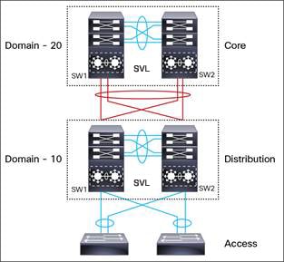
Figure 1. Typical Network Design using Cisco StackWise Virtual
Etherchannel in StackWise Virtual is capable of implementing Multi-chassis EtherChannel (MEC) across the stack members. When
access layer and aggregation layer are collapsed into a single StackWise Virtual system, MEC across the different access layer
domain members and across distribution and access layer switches will not be supported. MEC is designed to forward the traffic
over the local link irrespective of the hash result.
Since the control plane, management plane, and data plane are integrated, the system behaves as a single switch.
The virtualization of multiple physical switches into a single logical switch is from a control and management plane perspective
only. Because of the control plane being common, it may look like a single logical entity to peer switches. The data plane
of the switches is distributed. Each switch is capable of forwarding over its local interfaces without involving other members.
However, when a packet coming into a switch has to be forwarded over a different member’s port, the forwarding context of
the packet is carried over to the destination switch after ingress processing is performed in the ingress switch. Egress processing
is done only in the egress switch. This provides a uniform data plane behavior to the entire switch irrespective whether of
the destination port is in a local switch or in a remote switch. However, the common control plane ensures that all the switches
have equivalent data plane entry for each forwarding entity.
An election mechanism elects one of the switches to be Cisco StackWise Virtual active and the other switch to be Cisco StackWise
Virtual standby in terms of Control Plane functions. The active switch is responsible for all the management, bridging and
routing protocols, and software data path. The standby switch is in hot standby state ready to take over the role of active,
if the active switch fails over.
The following are the components of the Cisco StackWise Virtual solution:
Stack members
SVL: 10G, 25G, 40G or 100G Ethernet connections. SVL is established using the 10G, 25G, 40G or 100G interfaces depending on
the switch models. However, a combination of two different speeds is not supported.
SVL is the link that connects the switches over Ethernet. Typically, Cisco StackWise Virtual consists of multiple 100G, 25G, 40G or 10G physical links. It carries all the control and data traffic between the switching units. You can configure
SVL on a supported port. When a switch is powered up and the hardware is initialized, it looks for a configured SVL before
the initialization of the control plane.
The Link Management Protocol (LMP) is activated on each link of the SVL as soon as the links are established. LMP ensure the
integrity of the links and monitors and maintains the health of the links. The redundancy role of each switch is resolved
by the StackWise Discovery Protocol (SDP). It ensures that the hardware and software versions are compatible to form the SVL
and determines which switch becomes active or standby from a control plane perspective.
Cisco StackWise Virtual Header (SVH) is 64-byte frame header that is prepended over all control, data, and management plane
traffic that traverse over each SVL between the two stack members of the Cisco StackWise Virtual domain. The SVH-encapsulated
traffic operates at OSI Layer 2 and can be recognized and processed only by Cisco StackWise Virtual-enabled switches. SVL
interfaces are non-bridgeable and non-routeable, and allows non-routeable traffic over L2 or L3 network.
Cisco StackWise Virtual Redundancy
Cisco StackWise Virtual operates stateful switchover (SSO) between the active and standby switches. The following are the
ways in which Cisco StackWise Virtual's redundancy model differs from that of the standalone mode:
The Cisco StackWise Virtual active and standby switches are hosted in separate switches and use a StackWise Virtual link to
exchange information.
The active switch controls both the switches of Cisco StackWise Virtual. The active switch runs the Layer 2 and Layer 3 control
protocols and manages the switching modules of both the switches.
The Cisco StackWise Virtual active and standby switches perform data traffic forwarding.
Note
If the Cisco StackWise Virtual active switch fails, the standby switch initiates a switchover and assumes the Cisco StackWise
Virtual active switch role.
SSO Redundancy
A StackWise Virtual system operates with SSO redundancy if it meets the following requirements:
Both the switches must be running the same software version, unless they are in the process of software upgrade.
SVL-related configuration in the two switches must match.
License type must be same on both the switch models.
Both the switch models must be in the same StackWise Virtual domain.
With SSO redundancy, the StackWise Virtual standby switch is always ready to assume control if a fault occurs on the StackWise
Virtual active switch. Configuration, forwarding, and state information are synchronized from the StackWise Virtual active
switch to the redundant switch at startup, and whenever changes to the StackWise Virtual active switch configuration occur.
If a switchover occurs, traffic disruption is minimized.
If StackWise Virtual does not meet the requirements for SSO redundancy, it will be incapable of establishing a relationship
with the peer switch. StackWise Virtual runs stateful switchover (SSO) between the StackWise Virtual active and standby switches.
The StackWise Virtual determines the role of each switch during initialization.
The CPU in the StackWise Virtual standby switch runs in hot standby state. StackWise Virtual uses SVL to synchronize configuration
data from the StackWise Virtual active switch to the StackWise Virtual standby switch. Also, protocols and features that support
high availability synchronize their events and state information to the StackWise Virtual standby switch.
Nonstop Forwarding
While implementing Nonstop Forwarding (NSF) technology in systems using SSO redundancy mode, network disruptions are minimized
for campus users and applications. High availability is provided even when the control-plane processing stack-member switch
is reset. During a failure of the underlying Layer 3, NSF-capable protocols perform graceful network topology resynchronization.
The preset forwarding information on the redundant stack-member switch remains intact; this switch continues to forward the
data in the network. This service availability significantly lowers the mean time to repair (MTTR) and increases the mean
time between failure (MTBF) to achieve a high level of network availability.
Multichassis EtherChannels
Multichassis EtherChannel (MEC) is an EtherChannel bundled with physical ports having common characteristics such as speed
and duplex, that are distributed across each Cisco StackWise Virtual system. A Cisco StackWise Virtual MEC can connect to
any network element that supports EtherChannel (such as a host, server, router, or switch).
Cisco StackWise Virtual supports up to 192 MECs deployed in Layer 2 or Layer 3 modes.
EtherChannel 127 and 128 are reserved for SVL connections. Hence, the maximum available MEC count is 126.
In a Cisco StackWise Virtual system, an MEC is an EtherChannel with additional capability. A multichassis EtherChannel link
reduces the amount of traffic that requires transmission across the SVL by populating the index port only with the ports local
to the physical switch. This allows the switch to give precedence to the local ports of the multichassis EtherChannel link
over those on the remote switch.
Each MEC can optionally be configured to support either Cisco PAgP, IEEE LACP, or Static ON mode. We recommend that you implement
EtherChannel using Cisco PAgP or LACP with a compatible neighbor. If a remotely connected neighbor such as Cisco Wireless
LAN Controller (WLC) does not support this link-bundling protocol, then a Static ON mode can be deployed. These protocols
run only on the Cisco StackWise Virtual active switch.
An MEC can support up to eight physical links that can be distributed in any proportion between the Cisco StackWise Virtual
active switch and the Cisco StackWise Virtual standby switch. We recommend that you distribute the MEC ports across both switches
evenly.
MEC Minimum Latency Load Balancing
The StackWise Virtual environment is designed such that data forwarding always remains within the switch. The Virtual Stack
always tries to forward traffic on the locally available links. This is true for both Layer 2 and Layer3 links. The primary
motivation for local forwarding is to avoid unnecessarily sending data traffic over the SVL and thus reduce the latency (extra
hop over the SVL) and congestion.The bidirectional traffic is load-shared between the two StackWise Virtual members. However,
for each StackWise Virtual member, ingress and egress traffic forwarding is based on locally-attached links that are part
of MEC. This local forwarding is a key concept in understanding convergence and fault conditions in a StackWise Virtual enabled
campus network.
The active and standby switches support local forwarding that will individually perform the desired lookups and forward the
traffic on local links to uplink neighbors. If the destination is a remote switch in the StackWise Virtual domain, ingress
processing is performed on the ingress switch and then traffic is forwarded over the SVL to the egress switch where only egress
processing is performed.
MEC Failure Scenarios
The following sections describe issues that may arise and the resulting impact:
Single MEC Link Failure
If a link within a MEC fails (and other links in the MEC are still operational), the MEC redistributes the load among the
operational links, as in a regular port.
All MEC Links to the Cisco StackWise Virtual Active Switch Fail
If all the links to the Cisco StackWise Virtual active switch fail, a MEC becomes a regular EtherChannel with operational
links to the Cisco StackWise Virtual standby switch.
Data traffic that terminates on the Cisco StackWise Virtual active switch reaches the MEC by crossing the SVL to the Cisco
StackWise Virtual standby switch. Control protocols continue to run in the Cisco StackWise Virtual active switch. Protocol
messages reach the MEC by crossing the SVL.
All MEC Links Fail
If all the links in an MEC fail, the logical interface for the EtherChannel is set to Unavailable. Layer 2 control protocols
perform the same corrective action as for a link-down event on a regular EtherChannel.
On adjacent switches, routing protocols and the Spanning Tree Protocol (STP) perform the same corrective action as for a
regular EtherChannel.
Cisco StackWise Virtual Standby Switch Failure
If the Cisco StackWise Virtual standby switch fails, a MEC becomes a regular EtherChannel with operational links on the Cisco
StackWise Virtual active switch. Connected peer switches detect the link failures, and adjust their load-balancing algorithms
to use only the links to the StackWise Virtual active switch.
Cisco StackWise Virtual Active Switch Failure
Cisco StackWise Virtual active switch failure results in a stateful switchover (SSO). After the switchover, a MEC is operational
on the new Cisco StackWise Virtual active switch. Connected peer switches detect the link failures (to the failed switch),
and adjust their load-balancing algorithms to use only the links to the new Cisco StackWise Virtual active switch.
Cisco StackWise Virtual Packet Handling
In Cisco StackWise Virtual, the Cisco StackWise Virtual active switch runs the Layer 2 and Layer 3 protocols and features
and manages the ports on both the switches.
Cisco StackWise Virtual uses StackWise Virtual link to communicate system and protocol information between the peer switches
and to carry data traffic between the two switches.
The following sections describe packet handling in Cisco StackWise Virtual.
Traffic on StackWise Virtual link
SVL carries data traffic and in-band control traffic between two switches. All the frames that are forwarded over the SVL
are encapsulated with a special StackWise Virtual Header (SVH). The SVH adds an overhead of 64 bytes for control and data
traffic, which provides information for Cisco StackWise Virtual to forward the packet on the peer switch.
An SVL transports control messages between two switches. Messages include protocol messages that are processed by the Cisco
StackWise Virtual active switch, but received or transmitted by interfaces on the Cisco StackWise Virtual standby switch.
Control traffic also includes module programming between the Cisco StackWise Virtual active switch and the switching modules
on the Cisco StackWise Virtual standby switch.
Cisco StackWise Virtual transmits data traffic over an SVL under the following circumstances:
Layer 2 traffic flooded over a VLAN (even for dual-homed links).
Packets processed by software on the Cisco StackWise Virtual active switch where the ingress interface is on the Cisco StackWise
Virtual standby switch.
The packet destination is on the peer switch, as described in the following examples:
Traffic within a VLAN where the known destination interface is on the peer switch.
Traffic that is replicated for a multicast group and the multicast receivers are on the peer switch.
The known unicast destination MAC address is on the peer switch.
The packet is a MAC notification frame destined for a port on the peer switch.
An SVL also transports system data, such as NetFlow export data and SNMP data, from the Cisco StackWise Virtual standby switch
to the Cisco StackWise Virtual active switch.
Traffic on the SVL is load balanced with the same global hashing algorithms available for EtherChannels (the default algorithm
is source-destination IP and Port ).
Layer 2 Protocols
The Cisco StackWise Virtual active switch runs the Layer 2 protocols (such as STP and VTP) for the switching modules on both
the switches. Protocol messages that are received on the standby switch ports must traverse SVLs to reach the active switch
where they are processed. Similarly, protocol messages that are transmitted from the standby switch ports originate on the
active switch, and traverse the SVLs to reach the standby ports.
All the Layer 2 protocols in Cisco StackWise Virtual work similarly in standalone mode. The following sections describe the
difference in behavior for some protocols in Cisco StackWise Virtual.
Spanning Tree Protocol
The Cisco StackWise Virtual active switch runs the STP. The Cisco StackWise Virtual standby switch redirects the STP BPDUs
across an SVL to the StackWise Virtual active switch.
The STP bridge ID is commonly derived from the switch MAC address. To ensure that the bridge ID does not change after a switchover,
Cisco StackWise Virtual continues to use the original switch MAC address for the STP Bridge ID.
EtherChannel Control Protocols
Link Aggregation Control Protocol (LACP) and Port Aggregation Protocol (PAgP) packets contain a device identifier. Cisco
StackWise Virtual defines a common device identifier for both the switches. Use either PAgP or LACP on Multi EtherChannels
instead of mode ON, even if all the three modes are supported.
Note
A new PAgP enhancement has been defined for assisting with dual-active scenario detection.
Switched Port Analyzer
Switched Port Analyzer (SPAN) on SVL and fast hello DAD link ports is not supported. These ports can be neither a SPAN source,
nor a SPAN destination. Cisco StackWise Virtual supports all the SPAN features for non-SVL interfaces. The number of SPAN
sessions that are available on Cisco StackWise Virtual matches that on a single switch running in standalone mode.
Private VLANs
Private VLANs on StackWise Virtual work the same way as in standalone mode. The only exception is that the native VLAN on
isolated trunk ports must be configured explicitly.
Apart from STP, EtherChannel Control Protocols, SPAN, and private VLANs, the Dynamic Trunking Protocol (DTP), Cisco Discovery
Protocol (CDP), VLAN Trunk Protocol (VTP), and Unidirectional Link Detection Protocol (UDLD) are the additional Layer 2 control-plane
protocols that run over the SVL connections.
Broadcast, Unknown Unicast and Multicast
Cisco StackWise Virtual supports local switching for Broadcast, Unknown unicast and Multicast (BUM) traffic. In uncommon deployment
scenarios, BUM traffic traverses through the StackWise Virtual Links. This section explains how BUM traffic is handled in
a Cisco StackWise Virtual setup and in local switching.
When a VLAN is created, StackWise Virtual ports are added to the VLAN flood list. The ingress BUM traffic on active or standby
switch traverses through the StackWise Virtual link to the other switch instead of a port in the VLAN. This traffic floods
the StackWise Virtual links which impacts the system and network performance.
To address this, StackWise Virtual BUM optimization feature is introduced.
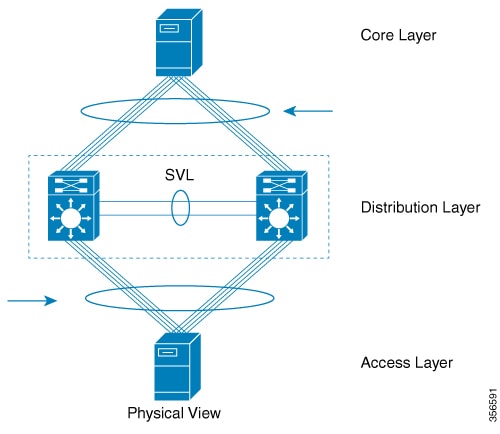
A general deployment guideline for Cisco StackWise Virtual is to distribute MEC ports evenly at the uplink and downlink as
shown in the figure. In this topology, BUM traffic prefers the local link on MEC to send the traffic out instead of the StackWise
Virtual link. In a scenario where there is a standalone port on a switch or members of EtherChannel on active or standby switch
are down, BUM traffic traverses the StackWise Virtual link. When StackWise Virtual BUM optimization is enabled on VLAN, StackWise
Virtual port is not added to the VLAN flood list. This design ensures BUM traffic does not traverse StackWise Virtual link
only when MEC port channels are part of the VLAN. No optimization is done for VLANs with standalone or physical ports.
Figure 2. Recommended Topology for Cisco StackWise Virtual
Layer 3 Protocols
The Cisco StackWise Virtual active switch runs the Layer 3 protocols and features for the StackWise Virtual. All the Layer
3 protocol packets are sent to and processed by the Cisco StackWise Virtual active switch. Both the member switches perform
hardware forwarding for ingress traffic on their interfaces. When software forwarding is required, packets are sent to the
Cisco StackWise Virtual active switch for processing.
The same router MAC address assigned by the Cisco StackWise Virtual active switch is used for all the Layer 3 interfaces
on both the Cisco StackWise Virtual member switches. After a switchover, the original router MAC address is still used. The
router MAC address is chosen based on chassis-mac and is preserved after switchover by default.
The following sections describe the Layer 3 protocols for Cisco StackWise Virtual.
IPv4 Unicast
The CPU on the Cisco StackWise Virtual active switch runs the IPv4 routing protocols and performs any required software forwarding.
All the routing protocol packets received on the Cisco StackWise Virtual standby switch are redirected to the Cisco StackWise
Virtual active switch across the SVL. The Cisco StackWise Virtual active switch generates all the routing protocol packets
to be sent out over ports on either of the Cisco StackWise Virtual member switches.
Hardware forwarding is distributed across both members on Cisco StackWise Virtual. The CPU on the Cisco StackWise Virtual
active switch sends Forwarding Information Base (FIB) updates to the Cisco StackWise Virtual standby switch, which in turn
installs all the routes and adjacencies into hardware.
Packets intended for a local adjacency (reachable by local ports) are forwarded locally on the ingress switch. Packets intended
for a remote adjacency (reachable by remote ports) must traverse the SVL.
The CPU on the Cisco StackWise Virtual active switch performs all software forwarding and feature processing (such as fragmentation
and Time to Live exceed functions). If a switchover occurs, software forwarding is disrupted until the new Cisco StackWise
Virtual active switch obtains the latest Cisco Express Forwarding and other forwarding information.
In virtual switch mode, the requirements to support non-stop forwarding (NSF) match those in the standalone redundant mode
of operation.
From a routing peer perspective, Multi-Chassis EtherChannels (MEC) remain operational during a switchover, that is, only
the links to the failed switch are down, but the routing adjacencies remain valid.
Cisco StackWise Virtual achieves Layer 3 load balancing over all the paths in the Forwarding Information Base entries, be
it local or remote.
IPv6
Cisco StackWise Virtual supports IPv6 unicast and multicast because it is present in the standalone system.
IPv4 Multicast
The IPv4 multicast protocols run on the Cisco StackWise Virtual active switch. Internet Group Management Protocol (IGMP)
and Protocol Independent Multicast (PIM) protocol packets received on the Cisco StackWise Virtual standby switch are transmitted
across an SVL to the StackWise Virtual active switch. The latter generates IGMP and PIM protocol packets to be sent over ports
on either of the Cisco StackWise Virtual members.
The Cisco StackWise Virtual active switch synchronizes the Multicast Forwarding Information Base (MFIB) state to the Cisco
StackWise Virtual standby switch. On both the member switches, all the multicast routes are loaded in the hardware, with replica
expansion table (RET) entries programmed for only local, outgoing interfaces. Both the member switches are capable of performing
hardware forwarding.
Note
To avoid multicast route changes as a result of a switchover, we recommend that all the links carrying multicast traffic
be configured as MEC rather than Equal Cost Multipath (ECMP).
For packets traversing an SVL, all Layer 3 multicast replications occur on the egress switch. If there are multiple receivers
on the egress switch, only one packet is replicated and forwarded over the SVL, and then replicated to all the local egress
ports.
Software Features
Software features run only on the Cisco StackWise Virtual active switch. Incoming packets to the Cisco StackWise Virtual
standby switch that require software processing are sent across an SVL to the Cisco StackWise Virtual active switch.
Dual-Active Detection
If the standby switch detects a complete loss of the SVL, it assumes the active switch has failed and will take over as the
active switch. However, if the original Cisco StackWise Virtual active switch is still operational, both the switches will
now be Cisco StackWise Virtual active switches. This situation is called a dual-active scenario. This scenario can have adverse
effects on network stability because both the switches use the same IP addresses, SSH keys, and STP bridge IDs. Cisco StackWise
Virtual detects a dual-active scenario and takes recovery action. DAD link is the dedicated link used to mitigate this.
If the last available SVL fails, the Cisco StackWise Virtual standby switch cannot determine the state of the Cisco StackWise
Virtual active switch. To ensure network uptime without delay, the Cisco StackWise Virtual standby switch then assumes the
Cisco StackWise Virtual active role. The original Cisco StackWise Virtual active switch enters recovery mode and brings down
all its interfaces, except the SVL and the management interfaces.
Dual-Active-Detection Link with Fast Hello
To use the dual-active fast hello packet detection method, you must provision a direct ethernet connection between the two
Cisco StackWise Virtual switches. You can dedicate up to four links for this purpose.
The two switches start with exchanging dual-active hello messages containing information about the initial switch states.
If all SVLs fail and a dual-active scenario occurs, each switch will trigger an exchange of the dual-active hello messages
which allows it to recognize that there is a dual-active scenario from the peer's messages.
This initiates recovery actions as described in the Recovery Actions section. If a switch does not receive an expected dual-active fast hello message from the peer before the timer expires,
the switch assumes that the link is no longer capable of dual-active detection.
Note
Do not use the same port for StackWise Virtual Link and dual-active detection link.
Dual-Active Detection with enhanced PAgP
Port aggregation protocol (PAgP) is a Cisco proprietary protocol used for managing EtherChannels. If a StackWise Virtual MEC
terminates on a Cisco switch, you can run PAgP protocol on the MEC. If PAgP is running on the MECs between the StackWise Virtual
switch and an upstream or downstream switch, the StackWise Virtual can use PAgP to detect a dual-active scenario. The MEC
must have at least one port on each switch of the StackWise Virtual setup.
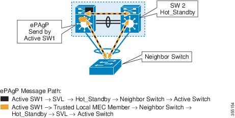
Enhanced PAgP is an extension of the PAgP protocol. In virtual switch mode, ePAgP messages include a new type length value
(TLV) which contains the ID of the StackWise Virtual active switch. Only switches in virtual switch mode send the new TLV.
When the StackWise Virtual standby switch detects SVL failure, it initiates SSO and becomes StackWise Virtual active. Subsequent
ePAgP messages sent to the connected switch from the newly StackWise Virtual active switch contain the new StackWise Virtual
active ID. The connected switch sends ePAgP messages with the new StackWise Virtual active ID to both StackWise Virtual switches.
If the formerly StackWise Virtual active switch is still operational, it detects the dual-active scenario because the StackWise
Virtual active ID in the ePAgP messages changes.
Figure 3. Dual-active-detection with ePAgP
Note
To avoid PAgP flaps and to ensure that dual-active detection functions as expected, the stack MAC persistent wait timer must
be configured as indefinite using the command stack-mac persistent timer 0 .
Recovery Actions
A Cisco StackWise Virtual active switch that detects a dual-active condition shuts down all of its non-SVL or non-DAD interfaces
to remove itself from the network. The switch then waits in recovery mode until the SVLs recover. You should physically repair
the SVL failure and the switch automatically reloads and restores itself as the standby switch. To enable the switch to remain
in recovery mode after restoring the SVL links, see Disabling Recovery Reload section.
Implementing Cisco StackWise Virtual
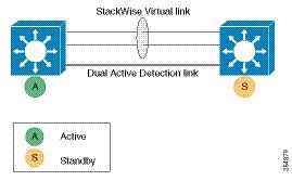
The two-node solution of Cisco StackWise Virtual is normally deployed at the aggregation layer. Two switches are connected
over an SVL.
Cisco StackWise Virtual combines the two switches into a single logical switch with a large number of ports, offering a single
point of management. One of the member switches is the active and works as the control and management plane, while the other
one is the standby. The virtualization of multiple physical switches into a single logical switch is only from a control and
management perspective. Because of the control plane being common, it may look like a single logical entity to peer switches.
The data plane of the switches are converged, that is, the forwarding context of a switch might be passed to the other member
switch for further processing when traffic is forwarded across the switches. However, the common control plane ensures that
all the switches have equivalent data plane entry for each forwarding entity.
Figure 4. Two-Node Solution
An election mechanism that determines which switch is Cisco StackWise Virtual active and which one is a control plane standby,
is available. The active switch is responsible for management, bridging and routing protocols, and software data path. These
are centralized on the active switch supervisor of the Cisco StackWise Virtual active switch.
How to Configure Cisco StackWise Virtual
Configuring Cisco StackWise Virtual Settings
To enable StackWise Virtual, perform the following procedure on both the switches:
Procedure
Command or Action
Purpose
Step 1
enable
Example:
Device>enable
Enables privileged EXEC mode.
Enter your password if prompted.
Step 2
switch switch-number renumber new switch -number
Example:
Device#switch 1 renumber 2
(Optional) Reassigns the switch number.
The default switch number will be 1. The valid values for the new switch number are 1 and 2.
Step 3
switch switch-number priority priority-number
Example:
Device#switch 1 priority 5
(Optional) Assigns the priority number.
The default priority number is 1. The highest priority number is 15.
Step 4
configureterminal
Example:
Device#configure terminal
Enters global configuration mode.
Step 5
stackwise-virtual
Example:
Device(config)#stackwise-virtual
Enables Cisco StackWise Virtual and enters stackwise-virtual submode.
Step 6
domain id
Example:
Device(config-stackwise-virtual)#domain 2
(Optional) Specifies the Cisco StackWise Virtual domain ID.
The domain ID range is from 1 to 255. The default value is one.
Step 7
end
Example:
Device(config-stackwise-virtual)#end
Returns to privileged EXEC mode.
Step 8
show stackwise-virtual
Example:
Device#show stackwise-virtual
Step 9
write memory
Example:
Device#write memory
Saves the running-configuration which resides in the system RAM and updates the ROMmon variables. If you do not save the changes,
the changes will no longer be part of the startup configuration when the switch reloads. Note that the configurations for
stackwise-virtual and domain are saved to the running-configuration and the startup-configuration after the reload.
Step 10
reload
Example:
Device#reload
Restarts the switch and forms the stack.
Configuring Cisco StackWise Virtual Link
Note
Depending on the switch model, SVL is supported on all 100G, 40G, 25G and 10G interfaces of the Cisco Catalyst 9600 Series
switches. However, a combination of different interface speeds is not supported.
To configure a switch port as an SVL port, perform the following procedure on both the switches:
Saves the running-configuration which resides in the system RAM and updates the ROMmon variables. If you do not save the changes,
the changes will no longer be part of the startup configuration when the switch reloads. Note that the configuration for stackwise-virtual link link value is saved only in the running-configuration and not the startup-configuration.
Step 7
reload
Example:
Device#reload
Restarts the switch.
Note
When converting a Cisco Catalyst 9600 Series switch from standalone mode to SVL mode for the first time, one of the switches
boots up or resets, for resolving the switch number conflict and sets the SWITCH_NUMBER environment variable to 2. The following
message appears on the console prompt indicating this:
Waiting for remote chassis to join
#######################################################################
Chassis number is 2
All chassis in the stack have been discovered. Accelerating discovery

Chassis is reloading, reason: Configured Switch num conflicts with peer,
Changing local switch number to 2 and reloading to take effect
Configuring Secure StackWise Virtual
Before you begin
Note
Ensure that the devices are in a standalone mode.
Disable FIPS mode using the no fips authorization-key command before configuring the Secure StackWise Virtual authorization key.
Procedure
Command or Action
Purpose
Step 1
enable
Example:
Device> enable
Enables privileged EXEC mode. Enter your password if prompted.
Associates the interface with StackWise Virtual dual-active-detection.
Note
This command will not be visible on the device after the configuration, but will continue to function.
Step 5
end
Example:
Device(config-if)#end
Returns to privileged EXEC mode.
Step 6
write memory
Example:
Device#write memory
Saves the running-configuration which resides in the system RAM and updates the ROMmon variables. If you do not save the changes,
the changes will no longer be part of the startup configuration when the switch reloads. Note that the configuration for stackwise-virtual dual-active-detection is saved only in the running-configuration and not the startup-configuration.
Step 7
reload
Example:
Device#reload
Restarts the switch and configuration takes effect.
Enabling ePAgP Dual-Active-Detection
To enable ePAgP dual-active-detection on a switch port, perform the following procedure on both the switches. This procedure is optional.
Enables dual-active detection trust mode on channel-group with the configured ID.
Step 12
exit
Example:
Device(config-stackwise-virtual)#exit
Exits the StackWise-Virtual configuration mode.
Step 13
interface port-channelportchannel
Example:
Device(config)#interface port-channel 1
Configured port-channel on the switch.
Step 14
no shutdown
Example:
Device(config-if)#no shutdown
Enables the configured port-channel on the switch.
Step 15
end
Example:
Device(config-if)#end
Exits interface configuration.
Step 16
write memory
Example:
Device#write memory
Saves the running-configuration which resides in the system RAM and updates the ROMmon variables. If you do not save the changes,
the changes will no longer be part of the startup configuration when the switch reloads. Note that the configuration for dual-active detection pagp trust channel-group channel-group id is saved to the running-configuration and the startup-configuration after the reload.
Step 17
reload
Example:
Device#reload
Restarts the switch and configuration takes effect.
Disabling Recovery Reload
After recovering from StackWise Virtual link failure, the switch in recovery mode performs a recovery action by automatically
reloading the switch . This is the default behaviour in the event of a link failure. In order to retain a switch in recovery
mode and prevent the switch from reloading automatically, you must perform the following steps.
Procedure
Command or Action
Purpose
Step 1
enable
Example:
Device>enable
Enables privileged EXEC mode.
Enter your password if prompted.
Step 2
configureterminal
Example:
Device#configure terminal
Enters global configuration mode.
Step 3
stackwise-virtual
Example:
Device(config)#stackwise-virtual
Enables Cisco StackWise Virtual and enters stackwise-virtual mode.
The following is a sample configuration for configuring SVL on a switch.
On Switch 1:
Device>enable
Device#configure terminal
Device(config)#interface FortyGigabitEthernet1/0/5
Device(config-if)#stackwise-virtual link 1
WARNING: All the extraneous configurations will be removed for FortyGigabitEthernet1/1/1 on reboot
INFO: Upon reboot, the config will be part of running config but not part of start up config.
Device(config-if)#end
Device#write memory
Device#reload
On Switch 2:
Device>enable
Device#configure terminal
Device(config)#interface FortyGigabitEthernet1/0/5
Device(config-if)#stackwise-virtual link 1
WARNING: All the extraneous configurations will be removed for FortyGigabitEthernet1/1/1 on reboot
INFO: Upon reboot, the config will be part of running config but not part of start up config.
Device(config-if)#end
Device#write memory
Device#reload
Example: Configuring Secure StackWise Virtual
The following is a sample configuration for configuring Secure StackWise Virtual.
Example: Displaying Secure StackWise Virtual Authorization Key and Status
The following is an example displaying the Secure StackWise Virtual authorization key.
Device# show secure-stackwise-virtual authorization-key
Secure-stackwise-virtual: Stored key (16) : 12345678901234567890123456789012
The following is an example displaying the Secure StackWise Virtual authorization key status.
Device# show secure-stackwise-virtual status
Switch is running in SECURE-SVL mode
Example: Disabling Secure StackWise Virtual
The following is an example of Secure StackWise Virtual authorization key zeroization.
Device(config)# secure-stackwise-virtual zeroize sha1-key
**Critical Warning** - This command is irreversible
and will zeroize the Secure-SVL-VPK by Deleting
the IOS image and config files, please use extreme
caution and confirm with Yes on each of three
iterations to complete. The system will reboot
after the command executes successfully
Do you want to proceed ?? (yes/[no]):
Example: Configuring StackWise Virtual Fast Hello Dual-Active-Detection Link
The following is a sample configuration for configuring a StackWise Virtual Fast Hello dual-active-detection link on a Switch
1 and Switch 2. You cannot configure StackWise Virtual Fast Hello dual-active-detection links on ports that are already configured
as StackWise Virtual link ports.
On Switch 1:
Device>enable
Device#configure terminal
Device(config)#interface FortyGigabitEthernet1/0/3
Device(config-if)#stackwise-virtual dual-active-detection
Please reload the switch for Stackwise Virtual configuration to take effect
Upon reboot, the config will be part of running config but not part of start up config.
Device(config-if)#exit
On Switch 2:
Device(config)#interface FortyGigabitEthernet1/0/3
Device(config-if)#stackwise-virtual dual-active-detection
Please reload the switch for Stackwise Virtual configuration to take effect
Upon reboot, the config will be part of running config but not part of start up config.
Device(config-if)#end
On both the switches:
Device#write memory
Device#reload
Example: Displaying StackWise Virtual Link Information
Sample output of show stackwise-virtual link command
In this example, the output is displayed from a switch where SVL is configured.
Device#show stackwise-virtual link
Stackwise Virtual Link(SVL) Information:
----------------------------------------
Flags:
------
Link Status
-----------
U-Up D-Down
Protocol Status
---------------
S-Suspended P-Pending E-Error T-Timeout R-Ready
-----------------------------------------------
Switch       SVL      Ports                            Link-Status        Protocol-Status
------       ---      -----                            -----------        ---------------
1            1        FortyGigabitEthernet1/1/0/5          U                  R
2            1        FortyGigabitEthernet2/1/0/5          U                  R
By default in standalone mode, the switches are identified as Switch 1 unless explicitly changed to some other switch number.
During the conversion to StackWise Virtual, the switch numbers are changed automatically to reflect two switches in a StackWise
Virtual domain.
In Cisco Catalyst 9600 Series Switches, the interface numbering will be in 4 tuple format after reload and the switch conversion
to Cisco StackWise Virtual
Example: Displaying StackWise Virtual Dual-Active-Detection Link Information
Sample output of show stackwise-virtual dual-active-detection command
StackWise Virtual DAD links configuration:
Device#show stackwise-virtual dual-active-detectionRecovery Reload for switch 1: Enabled
Recovery Reload for switch 2: Enabled
Dual-Active-Detection Configuration:
-------------------------------------
Switch Dad port Status
------ ------------ ---------
1 FortyGigabitEthernet1/1/0/3 up
2 FortyGigabitEthernet2/1/0/3 up
StackWise Virtual DAD links configuration after configuring the dual-active recovery-reload-disable command:
Device#show stackwise-virtual dual-active-detection
Recovery Reload for switch 1: Disabled
Recovery Reload for switch 2: Disabled
Dual-Active-Detection Configuration:
-------------------------------------
Switch Dad port Status
------ ------------ ---------
1 FortyGigabitEthernet1/1/0/3 up
2 FortyGigabitEthernet2/1/0/3 up
Sample output of show stackwise-virtual dual-active-detection epagp command
StackWise Virtual DAD ePAgP information:
Device#show stackwise-virtual dual-active-detection pagp
Pagp dual-active detection enabled: Yes
In dual-active recovery mode: No
Recovery Reload for switch 1: Enabled
Recovery Reload for switch 2: Enabled

Channel group 11
                  Dual-Active           Partner              Partner         Partner
Port              Detect Capable        Name                 Port            Version
Fo1/1/0/17          Yes                   SwitchA              Hu2/0/1         1.1
Fo2/1/0/21          Yes                   SwitchA              Hu1/0/4         1.1
Partner Name and Partner Port fields in the output represent the name and the ports of the peer switch to which the PagP port-channel is connected through
MEC.
Verifying Cisco StackWise Virtual Configuration
To verify your StackWise Virtual configuration, use the following show commands:
show stackwise-virtual switch number <1-2>
Displays information of a particular switch in the stack.
show stackwise-virtual link
Displays StackWise Virtual link information.
show secure-stackwise-virtual authorization-key
Displays the installed Secure StackWise Virtual authorization key.
show secure-stackwise-virtual status
Displays the Secure StackWise Virtual status.
show secure-stackwise-virtual interface
Displays the Secure StackWise Virtual interface statistics.
show stackwise-virtual bandwidth
Displays the bandwidth available for the Cisco StackWise Virtual.
(Optional)Assigns a new switch number. The default number is 1.
Additional References for StackWise Virtual
Related Documents
Related Topic
Document Title
For complete syntax and usage information for the commands used in this chapter.
High Availability Command Reference for Catalyst 9600 Switches
Feature History for Cisco StackWise Virtual
This table provides release and related information for features explained in this module.
These features are available on all releases subsequent to the one they were introduced in, unless noted otherwise.
Release
Feature
Feature Information
Cisco IOS XE Gibraltar 16.12.1
Cisco StackWise Virtual
Cisco StackWise Virtual is a network system virtualization technology that pairs two switches into one virtual switch to simplify
operational efficiency with a single control and management plane
Also supported in the introductory release, are the following features:
BGP EVPN VXLAN on switches with Cisco StackWise Virtual: Support for the BGP EVPN VXLAN feature on switches with Cisco StackWise Virtual configured.
Secure StackWise Virtual: Secure StackWise Virtual support was introduced for two node front-side stacking. Secure StackWise
Virtual is FIPS 140-2 compliant and encrypts control packets as well.
Recovery Reload: Support for disabling DAD recovery reload. Enter the dual-active recovery-reload-disable command in stackwise virtual mode (config-stackwise-virtual).
Cisco IOS XE Amsterdam 17.2.1
BUM Traffic Optimization on switches with Cisco StackWise Virtual
Support for the BUM Traffic Optimization feature was introduced on switches with Cisco StackWise Virtual configured.
Cisco StackWise Virtual: Interface and line card configurations
DAD links are now supported for the following interface and line card configurations:
1G interface on a C9600-LC-48TX line card.
1G interface if configured between a C9600-LC-48TX line card and either a C9600-LC-48YL line card or a C9600-LC-24C line card.
1G interface and 10G interface if configured between two C9600-LC-48YL line cards or between two C9600-LC-24C line cards.
1G interface and 10G interface if configured between a C9600-LC-48YL line card and a C9600-LC-24C line card.
Use the Cisco Feature Navigator to find information about platform and software image support. To access Cisco Feature Navigator,
go to https://cfnng.cisco.com/.

 Feedback