MPLS Layer 3 VPNs
An MPLS Virtual Private Network (VPN) consists of a set of sites that are interconnected by means of a Multiprotocol Label Switching (MPLS) provider core network. At each customer site, one or more customer edge (CE) devices attach to one or more provider edge (PE) devices. This module explains how to create an MPLS VPN.
Prerequisites for MPLS Virtual Private Networks
-
Make sure that you have installed Multiprotocol Label Switching (MPLS), Label Distribution Protocol (LDP), and Cisco Express Forwarding in your network.
-
All devices in the core, including the provider edge (PE) devices, must be able to support Cisco Express Forwarding and MPLS forwarding. See the “Assessing the Needs of the MPLS Virtual Private Network Customers” section.
-
Enable Cisco Express Forwarding on all devices in the core, including the PE devices. For information about how to determine if Cisco Express Forwarding is enabled, see the “Configuring Basic Cisco Express Forwarding” module in the Cisco Express Forwarding Configuration Guide.
-
The mpls ldp graceful-restart command must be configured to enable the device to protect LDP bindings and MPLS forwarding state during a disruption in service. We recommend you to configure this command (even if you do not want to preserve the forwarding state) to avoid device failure during SSO in a high availability setup with scale configurations.
Restrictions for MPLS Virtual Private Networks
When static routes are configured in a Multiprotocol Label Switching (MPLS) or MPLS virtual private network (VPN) environment, some variations of the ip route and ip route vrf commands are not supported. Use the following guidelines when configuring static routes.
Supported Static Routes in an MPLS Environment
The following ip route command is supported when you configure static routes in an MPLS environment:
-
ip route destination-prefix mask interface next-hop-address
The following ip route commands are supported when you configure static routes in an MPLS environment and configure load sharing with static nonrecursive routes and a specific outbound interface:
-
ip route destination-prefix mask interface1 next-hop1
-
ip route destination-prefix mask interface2 next-hop2
Unsupported Static Routes in an MPLS Environment That Uses the TFIB
The following ip route command is not supported when you configure static routes in an MPLS environment:
-
ip route destination-prefix mask next-hop-address
The following ip route command is not supported when you configure static routes in an MPLS environment and enable load sharing where the next hop can be reached through two paths:
-
ip route destination-prefix mask next-hop-address
The following ip route commands are not supported when you configure static routes in an MPLS environment and enable load sharing where the destination can be reached through two next hops:
-
ip route destination-prefix mask next-hop1
-
ip route destination-prefix mask next-hop2
Use the interface an next-hop arguments when specifying static routes.
Supported Static Routes in an MPLS VPN Environment
The following ip route vrf commands are supported when you configure static routes in an MPLS VPN environment, and the next hop and interface are in the same VRF:
-
ip route vrf vrf-name destination-prefix mask next-hop-address
-
ip route vrf vrf-name destination-prefix mask interface next-hop-address
-
ip route vrf vrf-name destination-prefix mask interface1 next-hop1
-
ip route vrf vrf-name destination-prefix mask interface2 next-hop2
The following ip route vrf commands are supported when you configure static routes in an MPLS VPN environment, and the next hop is in the global table in the MPLS cloud in the global routing table. For example, these commands are supported when the next hop is pointing to the Internet gateway.
-
ip route vrf vrf-name destination-prefix mask next-hop-address global
-
ip route vrf vrf-name destination-prefix mask interface next-hop-address (This command is supported when the next hop and interface are in the core.)
The following ip route commands are supported when you configure static routes in an MPLS VPN environment and enable load sharing with static nonrecursive routes and a specific outbound interface:
-
ip route destination-prefix mask interface1 next-hop1
-
ip route destination-prefix mask interface2 next-hop2
Unsupported Static Routes in an MPLS VPN Environment That Uses the TFIB
The following ip route command is not supported when you configure static routes in an MPLS VPN environment, the next hop is in the global table in the MPLS cloud within the core, and you enable load sharing where the next hop can be reached through two paths:
-
ip route vrf destination-prefix mask next-hop-address global
The following ip route commands are not supported when you configure static routes in an MPLS VPN environment, the next hop is in the global table in the MPLS cloud within the core, and you enable load sharing where the destination can be reached through two next hops:
-
ip route vrf destination-prefix mask next-hop1 global
-
ip route vrf destination-prefix mask next-hop2 global
The following ip route vrf commands are not supported when you configure static routes in an MPLS VPN environment, and the next hop and interface are in the same VRF:
-
ip route vrf vrf-name destination-prefix mask next-hop1 vrf-name destination-prefix mask next-hop1
-
ip route vrf vrf-name destination-prefix mask next-hop2
Supported Static Routes in an MPLS VPN Environment Where the Next Hop Resides in the Global Table on the CE Device
The following ip route vrf command is supported when you configure static routes in an MPLS VPN environment, and the next hop is in the global table on the customer edge (CE) side. For example, the following command is supported when the destination prefix is the CE device’s loopback address, as in external Border Gateway Protocol (EBGP) multihop cases.
-
ip route vrf vrf-name destination-prefix mask interface next-hop-address
The following ip route commands are supported when you configure static routes in an MPLS VPN environment, the next hop is in the global table on the CE side, and you enable load sharing with static nonrecursive routes and a specific outbound interface:
-
ip route destination-prefix mask interface1 nexthop1
-
ip route destination-prefix mask interface2 nexthop2
Information About MPLS Virtual Private Networks
This section provides information about MPLS Virtual Private Networks:
MPLS Virtual Private Network Definition
Before defining a Multiprotocol Label Switching virtual private network (MPLS VPN), you must define a VPN in general. A VPN is:
-
An IP-based network delivering private network services over a public infrastructure
-
A set of sites that communicate with each other privately over the Internet or other public or private networks
Conventional VPNs are created by configuring a full mesh of tunnels or permanent virtual circuits (PVCs) to all sites in a VPN. This type of VPN is not easy to maintain or expand, because adding a new site requires changing each edge device in the VPN.
MPLS-based VPNs are created in Layer 3 and are based on the peer model. The peer model enables the service provider and the customer to exchange Layer 3 routing information. The service provider relays the data between the customer sites without the customer’s involvement.
MPLS VPNs are easier to manage and expand than conventional VPNs. When a new site is added to an MPLS VPN, only the service provider’s edge device that provides services to the customer site needs to be updated.
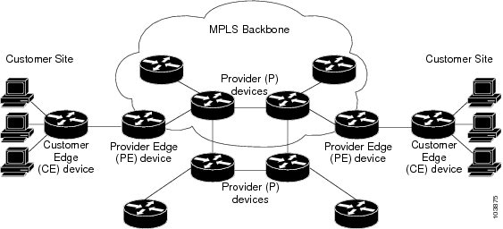
The different parts of the MPLS VPN are described as follows:
-
Provider (P) device—Device in the core of the provider network. P devices run MPLS switching, and do not attach VPN labels to routed packets. The MPLS label in each route is assigned by the provider edge (PE) device. VPN labels are used to direct data packets to the correct egress device.
-
PE device—Device that attaches the VPN label to incoming packets based on the interface or subinterface on which they are received. A PE device attaches directly to a customer edge (CE) device.
-
Customer (C) device—Device in the ISP or enterprise network.
-
CE device—Edge device on the network of the ISP that connects to the PE device on the network. A CE device must interface with a PE device.
The figure below shows a basic MPLS VPN.
How an MPLS Virtual Private Network Works
Multiprotocol Label Switching virtual private network (MPLS VPN) functionality is enabled at the edge of an MPLS network. The provider edge (PE) device performs the following:
-
Exchanges routing updates with the customer edge (CE) device.
-
Translates the CE routing information into VPNv4 routes.
-
Exchanges VPNv4 routes with other PE devices through the Multiprotocol Border Gateway Protocol (MP-BGP).
The following sections describe how MPLS VPN works:
Major Components of an MPLS Virtual Private Network
A Multiprotocol Label Switching (MPLS)-based virtual private network (VPN) has three major components:
-
VPN route target communities—A VPN route target community is a list of all members of a VPN community. VPN route targets need to be configured for each VPN community member.
-
Multiprotocol BGP (MP-BGP) peering of VPN community provider edge (PE) devices— MP-BGP propagates virtual routing and forwarding (VRF) reachability information to all members of a VPN community. MP-BGP peering must be configured on all PE devices within a VPN community.
-
MPLS forwarding—MPLS transports all traffic between all VPN community members across a VPN service-provider network.
A one-to-one relationship does not necessarily exist between customer sites and VPNs. A given site can be a member of multiple VPNs. However, a site can associate with only one VRF. A customer-site VRF contains all the routes available to the site from the VPNs of which it is a member.
Benefits of an MPLS Virtual Private Network
Multiprotocol Label Switching virtual private networks (MPLS VPNs) allow service providers to deploy scalable VPNs. They build the foundation to deliver value-added services, such as the following:
Connectionless Service
A significant technical advantage of MPLS VPNs is that they are connectionless. The Internet owes its success to its basic technology, TCP/IP. TCP/IP is built on a packet-based, connectionless network paradigm. This means that no prior action is necessary to establish communication between hosts, making it easy for two parties to communicate. To establish privacy in a connectionless IP environment, current VPN solutions impose a connection-oriented, point-to-point overlay on the network. Even if it runs over a connectionless network, a VPN cannot take advantage of the ease of connectivity and multiple services available in connectionless networks. When you create a connectionless VPN, you do not need tunnels and encryption for network privacy, thus eliminating significant complexity.
Centralized Service
Building VPNs in Layer 3 allows delivery of targeted services to a group of users represented by a VPN. A VPN must give service providers more than a mechanism for privately connecting users to intranet services. It must also provide a way to flexibly deliver value-added services to targeted customers. Scalability is critical, because you want to use services privately in their intranets and extranets. Because MPLS VPNs are seen as private intranets, you may use new IP services such as:
-
Multicast
-
Quality of service (QoS)
-
Telephony support within a VPN
-
Centralized services including content and web hosting to a VPN
You can customize several combinations of specialized services for individual customers. For example, a service that combines IP multicast with a low-latency service class enables video conferencing within an intranet.
Scalability
If you create a VPN using connection-oriented, point-to-point overlays, Frame Relay, or ATM virtual connections (VCs), the VPN’s key deficiency is scalability. Specifically, connection-oriented VPNs without fully meshed connections between customer sites are not optimal. MPLS-based VPNs, instead, use the peer model and Layer 3 connectionless architecture to leverage a highly scalable VPN solution. The peer model requires a customer site to peer with only one provider edge (PE) device as opposed to all other customer edge (CE) devices that are members of the VPN. The connectionless architecture allows the creation of VPNs in Layer 3, eliminating the need for tunnels or VCs.
Other scalability issues of MPLS VPNs are due to the partitioning of VPN routes between PE devices. And the further partitioning of VPN and Interior Gateway Protocol (IGP) routes between PE devices and provider (P) devices in a core network.
-
PE devices must maintain VPN routes for those VPNs who are members.
-
P devices do not maintain any VPN routes.
This increases the scalability of the provider’s core and ensures that no one device is a scalability bottleneck.
Security
MPLS VPNs offer the same level of security as connection-oriented VPNs. Packets from one VPN do not inadvertently go to another VPN.
Security is provided in the following areas:
-
At the edge of a provider network, ensuring packets that are received from a customer are placed on the correct VPN.
-
At the backbone, VPN traffic is kept separate. Malicious spoofing (an attempt to gain access to a PE device) is nearly impossible because the packets that are received from customers are IP packets. These IP packets must be received on a particular interface or subinterface to be uniquely identified with a VPN label.
Ease of Creation
To take full advantage of VPNs, customers must be able to easily create new VPNs and user communities. Because MPLS VPNs are connectionless, no specific point-to-point connection maps or topologies are required. You can add sites to intranets and extranets and form closed user groups. Managing VPNs in this manner enables membership of any given site in multiple VPNs, maximizing flexibility in building intranets and extranets.
Flexible Addressing
To make a VPN service more accessible, customers of a service provider can design their own addressing plan. This addressing plan can be independent of addressing plans for other service provider customers. Many customers use private address spaces, as defined in RFC 1918. They do not want to invest the time and expense of converting to public IP addresses to enable intranet connectivity. MPLS VPNs allow customers to continue to use their present address spaces without Network Address Translation (NAT) by providing a public and private view of the address. A NAT is required only if two VPNs with overlapping address spaces want to communicate. This enables customers to use their own unregistered private addresses, and communicate freely across a public IP network.
Integrated QoS Support
QoS is an important requirement for many IP VPN customers. It provides the ability to address two fundamental VPN requirements:
-
Predictable performance and policy implementation
-
Support for multiple levels of service in an MPLS VPN
Network traffic is classified and labeled at the edge of the network. The traffic is then aggregated according to policies defined by subscribers and implemented by the provider and transported across the provider core. Traffic at the edge and core of the network can then be differentiated into different classes by drop probability or delay.
Straightforward Migration
For service providers to quickly deploy VPN services, use a straightforward migration path. MPLS VPNs are unique because you can build them over multiple network architectures, including IP, ATM, Frame Relay, and hybrid networks.
Migration for the end customer is simplified because there is no requirement to support MPLS on the CE device. No modifications are required to a customer’s intranet.
How to Configure MPLS Virtual Private Networks
The following section provides the steps to configure MPLS Virtual Private Networks:
Configuring the Core Network
The following section provides the steps to configure the core network:
Assessing the Needs of MPLS Virtual Private Network Customers
Before you configure a Multiprotocol Label Switching virtual private network (MPLS VPN), you need to identify the core network topology so that it can best serve MPLS VPN customers. Perform this task to identify the core network topology.
Procedure
| Command or Action | Purpose | |
|---|---|---|
|
Step 1 |
Identify the size of the network. |
Identify the following to determine the number of devices and ports that you need:
|
|
Step 2 |
Identify the routing protocols in the core. |
Determine which routing protocols you need in the core network. |
|
Step 3 |
Determine if you need MPLS VPN High Availability support. |
MPLS VPN Nonstop Forwarding and Graceful Restart are supported on select devices and Cisco software releases. Contact Cisco Support for the exact requirements and hardware support. |
|
Step 4 |
Determine if you need Border Gateway Protocol (BGP) load sharing and redundant paths in the MPLS VPN core. |
For configuration steps, see the “Load Sharing MPLS VPN Traffic” feature module in the MPLS Layer 3 VPNs Inter-AS and CSC Configuration Guide. |
Configuring MPLS in the Core
To enable Multiprotocol Label Switching (MPLS) on all devices in the core, you must configure MPLS Label Distribution Protocol (LDP). For configuration information, see the “MPLS Label Distribution Protocol (LDP)” module in the MPLS Label Distribution Protocol Configuration Guide
Connecting the MPLS Virtual Private Network Customers
The following section provides information about Connecting the MPLS Virtual Private Network Customers:
Defining VRFs on the PE Devices to Enable Customer Connectivity
Use this procedure to define a virtual routing and forwarding (VRF) configuration for IPv4. To define a VRF for IPv4 and IPv6, see the “Configuring a Virtual Routing and Forwarding Instance for IPv6"section in the “IPv6 VPN over MPLS" module in the MPLS Layer 3 VPNs Configuration Guide.
Procedure
| Command or Action | Purpose | |
|---|---|---|
|
Step 1 |
enable Example: |
Enables privileged EXEC mode.
|
|
Step 2 |
configure terminal Example: |
Enters global configuration mode. |
|
Step 3 |
vrf definition vrf-name Example: |
Defines the virtual private network (VPN) routing instance by assigning a virtual routing and forwarding (VRF) name and enters VRF configuration mode.
|
|
Step 4 |
rd route-distinguisher Example: |
Creates routing and forwarding tables.
|
|
Step 5 |
address-family ipv4 | ipv6 Example: |
Enters IPv4 or IPv6 address family mode |
|
Step 6 |
route-target {import | export | both} route-target-ext-community Example: |
Creates a route-target extended community for a VRF.
|
|
Step 7 |
exit Example: |
(Optional) Exits to global configuration mode. |
Configuring VRF Interfaces on PE Devices for Each VPN Customer
To associate a virtual routing and forwarding (VRF) instance with an interface or subinterface on the provider edge (PE) devices, perform this task.
Procedure
| Command or Action | Purpose | |
|---|---|---|
|
Step 1 |
enable Example: |
Enables privileged EXEC mode.
|
|
Step 2 |
configure terminal Example: |
Enters global configuration mode. |
|
Step 3 |
interface type number Example: |
Specifies the interface to configure and enters interface configuration mode.
|
|
Step 4 |
vrf forwarding vrf-name Example: |
Associates a VRF with the specified interface or subinterface.
|
|
Step 5 |
end Example: |
(Optional) Exits to privileged EXEC mode. |
Configuring Routing Protocols Between the PE and CE Devices
Configure the provider edge (PE) device with the same routing protocol that the customer edge (CE) device uses. You can configure the Routing Information Protocol version 2 (RIPv2), EIGRP, Open Shortest Path First (OSPF) or static routes between the PE and CE devices.
Verifying the Virtual Private Network Configuration
A route distinguisher must be configured for the virtual routing and forwarding (VRF) instance. Multiprotocol Label Switching (MPLS) must be configured on the interfaces that carry the VRF. Use the show ip vrf command to verify the route distinguisher (RD) and interface configured for the VRF.
Procedure
|
show ip vrf Displays the set of defined VRF instances and associated interfaces. The output also maps the VRF instances to the configured route distinguisher. |
Verifying Connectivity Between MPLS Virtual Private Network Sites
To verify that the local and remote customer edge (CE) devices can communicate across the Multiprotocol Label Switching (MPLS) core, perform the following tasks:
Verifying IP Connectivity from CE Device to CE Device Across the MPLS Core
Procedure
|
Step 1 |
enable Enables privileged EXEC mode. |
|
Step 2 |
ping [protocol] {host-name | system-address} Diagnoses basic network connectivity on AppleTalk, Connectionless-mode Network Service (CLNS), IP, Novell, Apollo, Virtual Integrated Network Service (VINES), DECnet, or Xerox Network Service (XNS) networks. Use the ping command to verify the connectivity from one CE device to another. |
|
Step 3 |
trace [protocol] [destination] Discovers the routes that packets take when traveling to their destination. The trace command can help isolate a trouble spot if two devices cannot communicate. |
|
Step 4 |
show ip route [ip-address [mask] [longer-prefixes]] | protocol [process-id]] | [list [access-list-name | access-list-number] Displays the current state of the routing table. Use the ip-address argument to verify that CE1 has a route to CE2. Verify the routes learned by CE1. Make sure that the route for CE2 is listed. |
Verifying That the Local and Remote CE Devices Are in the PE Routing Table
Procedure
|
Step 1 |
enable Enables privileged EXEC mode. |
|
Step 2 |
show ip route vrf vrf-name [prefix] Displays the IP routing table that is associated with a virtual routing and forwarding (VRF) instance. Check that the loopback addresses of the local and remote customer edge (CE) devices are in the routing table of the provider edge (PE) devices. |
|
Step 3 |
show ip cef vrf vrf-name [ip-prefix] Displays the Cisco Express Forwarding forwarding table that is associated with a VRF. Check that the prefix of the remote CE device is in the Cisco Express Forwarding table. |
Configuration Examples for MPLS Virtual Private Networks
The following section provides the configuration examples for MPLS Virtual Private Networks:
Example: Configuring an MPLS Virtual Private Network Using RIP
|
PE Configuration |
CE Configuration |
|---|---|
|
|
Example: Configuring an MPLS Virtual Private Network Using Static Routes
|
PE Configuration |
CE Configuration |
|---|---|
|
|
Additional References
Related Documents
|
Related Topic |
Document Title |
|---|---|
|
For complete syntax and usage information for the commands used in this chapter. |
See the MPLS Commands section of the Command Reference (Catalyst 9600 Series Switches) |
|
Configuring Cisco Express Forwarding |
“Configuring Basic Cisco Express Forwarding” module in the Cisco Express Forwarding Configuration Guide |
|
Configuring LDP |
“MPLS Label Distribution Protocol (LDP)” module in the MPLS Label Distribution Protocol Configuration Guide |
Feature History for MPLS Virtual Private Networks
This table provides release and related information for features explained in this module.
These features are available on all releases subsequent to the one they were introduced in, unless noted otherwise.
|
Release |
Feature |
Feature Information |
|---|---|---|
|
Cisco IOS XE Gibraltar 16.11.1 |
MPLS Virtual Private Networks |
An MPLS Virtual Private Network (VPN) consists of a set of sites that are interconnected by means of a Multiprotocol Label Switching (MPLS) provider core network. At each customer site, one or more customer edge (CE) devices attach to one or more provider edge (PE) devices. |
Use Cisco Feature Navigator to find information about platform and software image support. To access Cisco Feature Navigator, go to http://www.cisco.com/go/cfn.
 Feedback