The documentation set for this product strives to use bias-free language. For the purposes of this documentation set, bias-free is defined as language that does not imply discrimination based on age, disability, gender, racial identity, ethnic identity, sexual orientation, socioeconomic status, and intersectionality. Exceptions may be present in the documentation due to language that is hardcoded in the user interfaces of the product software, language used based on RFP documentation, or language that is used by a referenced third-party product. Learn more about how Cisco is using Inclusive Language.
Information About EVPN VXLAN Layer 3 Overlay Network
An EVPN VXLAN Layer 3 overlay network allows host devices in different Layer 2 networks to send Layer 3 or routed traffic
to each other. The network forwards the routed traffic using a Layer 3 virtual network instance (VNI) and an IP VRF.
This module provides information only about how to configure a Layer 3 overlay network. You can also configure both Layer
2 and Layer 3 overlay networks together to enable integrated routing and bridging (IRB). For more information about IRB, see
Configuring EVPN VXLAN Integrated Routing and Bridging module.
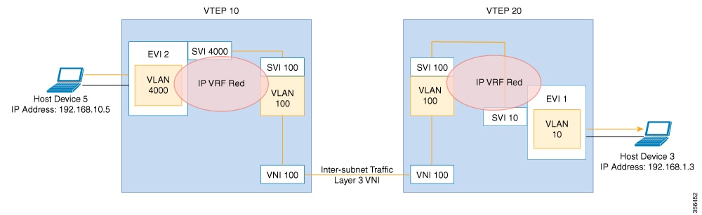
The following figure shows the movement of traffic in an EVPN VXLAN Layer 3 overlay network using a Layer 3 VNI:
How to Configure EVPN VXLAN Layer 3 Overlay Network
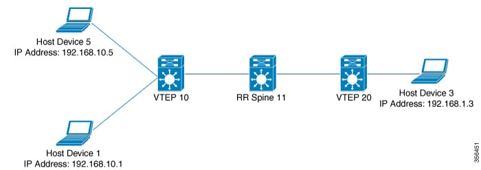
The following figure shows a sample topology of an EVPN VXLAN Network. Host device 3 and host device 5 are part of different
subnets. The network forwards traffic from host device 1 to host device 3 using a Layer 3 VNI and an IP VRF.
Note
In a two-VTEP topology, a spine switch is not mandatory. For information about configuration of spine switches in an EVPN
VXLAN network, see Configuring Spine Switches in a BGP EVPN VXLAN Fabric module.
Perform the following set of procedures to configure an EVPN VXLAN Layer 3 overlay network:
Configure the IP VRF on the VTEPs.
Configure the core-facing VLAN on the VTEPs.
Configure the access-facing VLAN on the VTEPs.
Configure the switch virtual interface (SVI) for the core-facing VLAN.
Configure the SVI for the access-facing VLAN.
Configure the loopback interface on the VTEPs.
Configure the network virtualization endpoint (NVE) interface on the VTEPs.
Configure BGP with either IPv4 or IPv6 or both address families on the VTEPs.
Configuring an IP VRF on a VTEP
To configure an IP VRF on a VTEP, perform the following steps:
Procedure
Command or Action
Purpose
Step 1
enable
Example:
Device> enable
Enables privileged EXEC mode.
Enter your password, if prompted.
Step 2
configure terminal
Example:
Device# configure terminal
Enters global configuration mode.
Step 3
vrf definition vrf-name
Example:
Device(config)# vrf definition Green
Enters the VRF configuration mode for the specified VRF instance.
Step 4
rd vpn-route-distinguisher
Example:
Device(config-vrf)# rd 100:1
Specifies the route distinguisher for the VRF instance.
Step 5
address-family ipv4 [ multicast | unicast]
Example:
Device(config-vrf)# address-family ipv4
Enters the IPv4 address family configuration mode.
Configures importing, exporting, or both importing and exporting of VXLAN route target communities for the VRF.
Step 12
exit-address-family
Example:
Device(config-vrf-af)# exit-address-family
Exits VRF address family configuration mode and enters VRF configuration mode.
Step 13
end
Example:
Device(config-vrf)# end
Returns to privileged EXEC mode.
Configuring the Core-facing VLAN on a VTEP
To configure the core-facing VLAN on a VTEP, perform the following steps:
Procedure
Command or Action
Purpose
Step 1
enable
Example:
Device> enable
Enables privileged EXEC mode.
Enter your password, if prompted.
Step 2
configure terminal
Example:
Device# configure terminal
Enters global configuration mode.
Step 3
vlan configuration vlan-id
Example:
Device(config)# vlan configuration 11
Enters VLAN feature configuration mode for the specified VLAN interface.
Step 4
member vni l3-vni-number
Example:
Device(config-vlan)# member vni 5000
Adds EVPN instance as a member of the VLAN configuration.
The VNI here is used as a Layer 3 VNI.
Step 5
end
Example:
Device(config-vlan)# end
Returns to privileged EXEC mode.
Configuring Access-facing VLAN on a VTEP
To configure the access-facing VLAN on a VTEP, perform the following steps:
Procedure
Command or Action
Purpose
Step 1
enable
Example:
Device> enable
Enables privileged EXEC mode.
Enter your password, if prompted.
Step 2
configure terminal
Example:
Device# configure terminal
Enters global configuration mode.
Step 3
interface interface-name
Example:
Device(config)# interface GigabitEthernet1/0/1
Enters interface configuration mode for the specified interface.
Step 4
switchport access vlan vlan-id
Example:
Device(config-if)# switchport access vlan 40
Configures the interface as a static-access port of the specified VLAN.
Interface can also be configured as a trunk interface, if required.
Step 5
end
Example:
Device(config-if)# end
Returns to privileged EXEC mode.
Configuring Switch Virtual Interface for the Core-facing VLAN
To configure an SVI for the core-facing VLAN on the VTEP:
Procedure
Command or Action
Purpose
Step 1
enable
Example:
Device> enable
Enables privileged EXEC mode.
Enter your password, if prompted.
Step 2
configure terminal
Example:
Device# configure terminal
Enters global configuration mode.
Step 3
interface vlan vlan-id
Example:
Device(config)# interface vlan 11
Enters interface configuration mode for the specified VLAN.
Step 4
vrf forwarding vrf-name
Example:
Device(config-if)# vrf forwarding Green
Configures the SVI for the VLAN.
Step 5
ip unnumberedLoopback-interface
Example:
Device(config-if)# ip unnumbered Loopback0
Enables IP processing on the Loopback interface without assigning an explicit IP address to the interface.
Step 6
no autostate
Example:
Device(config-if)# no autostate
Disables autostate on the interface.
In EVPN deployments, once a VLAN is used for a core-facing SVI, it should not be allowed in any trunk. For a core-facing SVI
to function properly, the no autostate command must be configured under the SVI.
Step 7
end
Example:
Device(config-if)# end
Returns to privileged EXEC mode.
Configuring the Switch Virtual Interface for the Access-facing VLANs
To configure the SVI for the access-facing VLAN on a VTEP, perform the following steps:
Procedure
Command or Action
Purpose
Step 1
enable
Example:
Device> enable
Enables privileged EXEC mode.
Enter your password, if prompted.
Step 2
configure terminal
Example:
Device# configure terminal
Enters global configuration mode.
Step 3
interface vlan vlan-id
Example:
Device(config)# interface vlan 40
Enters interface configuration mode for the specified VLAN.
Step 4
vrf forwarding vrf-name
Example:
Device(config-if)# vrf forwarding Green
Configures the SVI for the VLAN.
Step 5
ip addressip-address
Example:
Device(config-if)# ip address 192.168.10.100 255.255.255.0
Configures the IP address of the SVI.
Step 6
mac-addressmac-address-value
Example:
Device(config-if)# mac-address aabb.cc01.f100
(Optional) Manually sets the MAC address for the VLAN interface.
Step 7
exit
Example:
Device(config-if)# exit
Returns to global configuration mode.
Step 8
end
Example:
Device(config-if)# end
Returns to privileged EXEC mode.
Configuring the Loopback Interface on a VTEP
To configure the loopback interface on a VTEP, perform the following steps:
Procedure
Command or Action
Purpose
Step 1
enable
Example:
Device> enable
Enables privileged EXEC mode.
Enter your password, if prompted.
Step 2
configure terminal
Example:
Device# configure terminal
Enters global configuration mode.
Step 3
interface loopback-interface-id
Example:
Device(config)# interface Loopback0
Enters interface configuration mode for the specified Loopback interface.
Step 4
ip address ipv4-address
Example:
Device(config-if)# ip address 10.12.11.11 255.255.255.255
Configures the IP address for the Loopback interface.
Step 5
ip pim sparse mode
Example:
Device(config-if)# ip pim sparse mode
(Optional) Enables Protocol Independent Multicast (PIM) sparse mode on the Loopback interface.
Note
Enable PIM sparse mode only if EVPN VXLAN Layer 2 overlay network is also configured on the VTEP with underlay multicast as
the mechanism for forwarding BUM traffic.
Step 6
end
Example:
Device(config-vlan)# end
Returns to privileged EXEC mode.
Configuring the NVE Interface on a VTEP
To add a Layer 3 VNI member to the NVE interface on a VTEP, perform the following steps:
Procedure
Command or Action
Purpose
Step 1
enable
Example:
Device> enable
Enables privileged EXEC mode.
Enter your password, if prompted.
Step 2
configure terminal
Example:
Device# configure terminal
Enters global configuration mode.
Step 3
interface nve-interface-id
Example:
Device(config)# interface nve1
Defines the interface to be configured as a trunk, and enters interface configuration mode.
Step 4
no ip address
Example:
Device(config-if)# no ip address
Disables IP processing on the interface by removing its IP address.
Step 5
source-interface loopback-interface-id
Example:
Device(config-if)# source-interface loopback0
Sets the IP address of the specified loopback interface as the source IP address.
Step 6
host-reachability protocol bgp
Example:
Device(config-if)# host-reachability protocol bgp
Configures BGP as the host-reachability protocol on the interface.
Step 7
member vni vni-id vrf vrf-name
Example:
Device(config-if)# member vni 5000 vrf Green
Associates the Layer 3 VNI id with the NVE interface.
Note
The Layer 3 VNI id must match with the VNI id configured in the core VLAN on the VTEP.
Step 8
end
Example:
Device(config-if)# end
Returns to privileged EXEC mode.
Configuring BGP with IPv4 or IPv6 or Both Address Families on VTEP
To configure BGP on a VTEP with IPv4 or IPv6 or both address families and a spine switch as the neighbor, perform the following
steps:
Procedure
Command or Action
Purpose
Step 1
enable
Example:
Device> enable
Enables privileged EXEC mode.
Enter your password, if prompted.
Step 2
configure terminal
Example:
Device# configure terminal
Enters global configuration mode.
Step 3
router bgp autonomous-system-number
Example:
Device(config)# router bgp 1
Enables a BGP routing process, assigns it an autonomous system number, and enters router configuration mode.
Step 4
bgp log-neighbor-changes
Example:
Device(config-router)# bgp log-neighbor-changes
(Optional) Enables the generation of logging messages when the status of a BGP neighbor changes.
For more information, see Configuring BGP module of the IP Routing Configuration Guide.
Step 5
bgp update-delay time-period
Example:
Device(config-router)# bgp update-delay 1
(Optional) Sets the maximum initial delay period before sending the first update.
For more information, see Configuring BGP module of the IP Routing Configuration Guide.
Step 6
bgp graceful-restart
Example:
Device(config-router)# bgp graceful-restart
(Optional) Enables the BGP graceful restart capability for all BGP neighbors.
For more information, see Configuring BGP module of the IP Routing Configuration Guide.
Step 7
no bgp default ipv4-unicast
Example:
Device(config-router)# no bgp default ipv4-unicast
(Optional) Disables default IPv4 unicast address family for BGP peering session establishment.
For more information, see Configuring BGP module of the IP Routing Configuration Guide.
Enables the exchange information from a BGP neighbor.
Use the IP address of the spine switch as the neighbor IP address.
Step 12
neighbor ip-address send-community [ both | extended | standard]
Example:
Device(config-router-af)# neighbor 10.11.11.11 send-community both
Specifies the communities attribute sent to a BGP neighbor.
Use the IP address of the spine switch as the neighbor IP address.
Step 13
exit-address-family
Example:
Device(config-router-af)# exit-address-family
Exits address family configuration mode and returns to router configuration mode.
Step 14
address-family ipv4 vrf vrf-name
Example:
Device(config-router)# address-family ipv4 vrf Green
Specifies the IPv4 address family and enters address family configuration mode.
Step 15
advertise l2vpn evpn
Example:
Device(config-router-af)# advertise l2vpn evpn
Advertises Layer 2 VPN EVPN routes within a tenant VRF in an EVPN VXLAN fabric.
Step 16
redistribute connected
Example:
Device(config-router-af)# redistribute connected
(Optional) Redistributes connected routes to BGP.
Step 17
redistribute static
Example:
Device(config-router-af)# redistribute static
(Optional) Redistributes static routes to BGP.
Step 18
exit-address-family
Example:
Device(config-router-af)# exit-address-family
Exits address family configuration mode and returns to router configuration mode.
Step 19
address-family ipv6 vrf vrf-name
Example:
Device(config-router)# address-family ipv6 vrf green
Specifies the IPv6 address family and enters address family configuration mode.
Step 20
advertise l2vpn evpn
Example:
Device(config-router-af)# advertise l2vpn evpn
Advertises Layer 2 VPN EVPN routes within a tenant VRF in an EVPN VXLAN fabric.
Step 21
redistribute connected
Example:
Device(config-router-af)# redistribute connected
(Optional) Redistributes connected routes to BGP.
Step 22
redistribute static
Example:
Device(config-router-af)# redistribute static
(Optional) Redistributes static routes to BGP.
Step 23
exit-address-family
Example:
Device(config-router-af)# exit-address-family
Exits address family configuration mode and returns to router configuration mode.
Step 24
end
Example:
Device(config-router)# end
Returns to privileged EXEC mode.
Configuration Examples for EVPN VXLAN Layer 3 Overlay Network
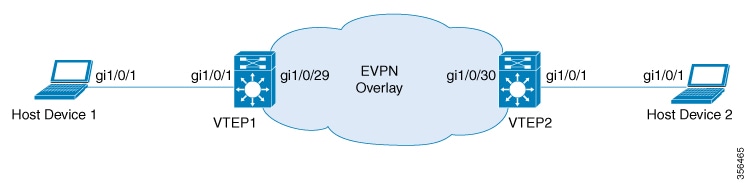
This section provides an example for configuring an EVPN VXLAN Layer 3 overlay network. This example shows a sample configuration
for a VXLAN network with 2 VTEPs, VTEP 1 and VTEP 2, connected to perform routing.
Note
In a two-VTEP topology, a spine switch is not mandatory. For information about configuration of spine switches in an EVPN
VXLAN network, see Configuring Spine Switches in a BGP EVPN VXLAN Fabric module.
Table 1. Configuration Example for a VXLAN Network with Two VTEPs Connected to Perform Routing
VTEP 1
VTEP 2
VTEP1# show running-config
!
hostname VTEP1
!
!
vrf definition green
 rd 103:2
 !
 address-family ipv4
  route-target export 103:2
  route-target import 104:2
  route-target export 103:2 stitching
  route-target import 104:2 stitching
 exit-address-family
 !
 address-family ipv6
  route-target export 103:2
  route-target import 104:2
  route-target export 103:2 stitching
  route-target import 104:2 stitching
 exit-address-family
!
ip multicast-routing
ipv6 unicast-routing
!
!
system mtu 9150
!
vlan configuration 200
 member vni 5000
!
!
interface Loopback0
 ip address 10.1.1.10 255.255.255.255
 ip pim sparse-mode
!
interface Loopback13
 description demo only (for rt5 distribution)
 vrf forwarding green
 ip address 10.1.13.13 255.255.255.0
!
interface GigabitEthernet1/0/1
description access interface
 switchport access vlan 201
 switchport mode access
!
!
interface GigabitEthernet1/0/29
 description core-underlay-interface
 no switchport
 ip address 172.16.1.29 255.255.255.0
 ip pim sparse-mode
!
!
interface Vlan200
 description core svi for l3vni
 vrf forwarding green
 ip unnumbered Loopback0
 ipv6 enable
 no autostate
!
interface Vlan201
 description access-svi
 vrf forwarding green
 ip address 192.168.1.201 255.255.255.0
 ipv6 address 2001:DB8:201::201/64
 ipv6 enable
!
interface nve10
 no ip address
 source-interface Loopback0
 host-reachability protocol bgp
 member vni 5000 vrf green
!
router ospf 1
 router-id 10.1.1.10
 network 10.1.1.0 0.0.0.255 area 0
 network 172.16.1.0 0.0.0.255 area 0
!
router bgp 10
 bgp router-id interface Loopback0
 bgp log-neighbor-changes
 bgp update-delay 1
 no bgp default ipv4-unicast
 neighbor 10.2.2.20 remote-as 10
 neighbor 10.2.2.20 update-source Loopback0
 !
 address-family ipv4
 exit-address-family
 !
 address-family l2vpn evpn
  neighbor 10.2.2.20 activate
  neighbor 10.2.2.20 send-community both
 exit-address-family
 !
 address-family ipv4 vrf green
  advertise l2vpn evpn
  redistribute connected
  redistribute static
 exit-address-family
 !
 address-family ipv6 vrf green
  redistribute connected
  redistribute static
  advertise l2vpn evpn
 exit-address-family
!
ip pim rp-address 10.1.1.10
!
!
end
VTEP2# show running-config
!
hostname VTEP2
!
!
vrf definition green
 rd 104:2
 !
 address-family ipv4
  route-target export 104:2
  route-target import 103:2
  route-target export 104:2 stitching
  route-target import 103:2 stitching
 exit-address-family
 !
 address-family ipv6
  route-target export 104:2
  route-target import 103:2
  route-target export 104:2 stitching
  route-target import 103:2 stitching
 exit-address-family
!
ip multicast-routing
ipv6 unicast-routing
!
!
system mtu 9150
!
vlan configuration 200
 member vni 5000
!
!
interface Loopback0
 ip address 10.2.2.20 255.255.255.255
 ip pim sparse-mode
!
interface Loopback14
 description demo only (for rt5 distribution)
 vrf forwarding green
 ip address 10.1.14.14 255.255.255.0
!
interface GigabitEthernet1/0/1
description access interface
 switchport access vlan 202
 switchport mode access
!
!
interface GigabitEthernet1/0/30
 description core-underlay-interface
 no switchport
 ip address 172.16.1.30 255.255.255.0
 ip pim sparse-mode
!
!
interface Vlan200
 description core svi for l3vni
 vrf forwarding green
 ip unnumbered Loopback0
 ipv6 enable
 no autostate
!
interface Vlan202
 description access-svi
 vrf forwarding green
 ip address 192.168.2.202 255.255.255.0
 ipv6 address 2001:DB8:202::202/64
 ipv6 enable
!
interface nve10
 no ip address
 source-interface Loopback0
 host-reachability protocol bgp
 member vni 5000 vrf green
!
router ospf 1
 router-id 10.2.2.20
 network 10.2.2.0 0.0.0.255 area 0
 network 172.16.1.0 0.0.0.255 area 0
!
router bgp 10
 bgp router-id interface Loopback0
 bgp log-neighbor-changes
 bgp update-delay 1
 no bgp default ipv4-unicast
 neighbor 10.1.1.10 remote-as 10
 neighbor 10.1.1.10 update-source Loopback0
 !
 address-family ipv4
 exit-address-family
 !
 address-family l2vpn evpn
  neighbor 10.1.1.10 activate
  neighbor 10.1.1.10 send-community both
 exit-address-family
 !
 address-family ipv4 vrf green
  advertise l2vpn evpn
  redistribute connected
  redistribute static
 exit-address-family
 !
 address-family ipv6 vrf green
  redistribute connected
  redistribute static
  advertise l2vpn evpn
 exit-address-family
!
ip pim rp-address 10.1.1.10
!
!
end
The following examples provide outputs for show commands on VTEP 1 and VTEP 2 in the topology configured above.
The following example shows the output for the show nve peers command on VTEP 1:
VTEP1# show nve peers
Interface  VNI      Type Peer-IP          RMAC/Num_RTs   eVNI     state flags UP time
nve10      5000     L3CP 10.2.2.20        380e.4d9b.6a4a 5000       UP  A/M/4 00:38:37
nve10      5000     L3CP 10.2.2.20        380e.4d9b.6a4a 5000       UP  A/-/6 00:03:16
VTEP 2
The following example shows the output for the show nve peers command on VTEP 2:
VTEP2# show nve peers
Interface  VNI      Type Peer-IP          RMAC/Num_RTs   eVNI     state flags UP time
nve10      5000     L3CP 10.1.1.10        a0f8.4910.bce2 5000       UP  A/-/4 00:38:53
nve10      5000     L3CP 10.1.1.10        a0f8.4910.bce2 5000       UP  A/M/6 00:38:53
show bgp l2vpn evpn all
VTEP 1
The following example shows the output for the show bgp l2vpn evpn all all command on VTEP 1:
VTEP1# show bgp l2vpn evpn all
BGP table version is 26, local router ID is 10.1.1.10
Status codes: s suppressed, d damped, h history, * valid, > best, i - internal,
              r RIB-failure, S Stale, m multipath, b backup-path, f RT-Filter,
              x best-external, a additional-path, c RIB-compressed,
              t secondary path, L long-lived-stale,
Origin codes: i - IGP, e - EGP, ? - incomplete
RPKI validation codes: V valid, I invalid, N Not found

     Network          Next Hop            Metric LocPrf Weight Path
Route Distinguisher: 103:2 (default for vrf green)
 *>   [5][103:2][0][24][10.1.13.0]/17
                      0.0.0.0                  0         32768 ?
 *>   [5][103:2][0][24][192.168.1.0]/17
                      0.0.0.0                  0         32768 ?
 *>   [5][103:2][0][64][2001:DB8:201::]/29
                      ::                       0         32768 ?
Route Distinguisher: 104:2
 *>i  [5][104:2][0][24][10.1.14.0]/17
                      10.2.2.20                0    100      0 ?
 *>i  [5][104:2][0][24][192.168.2.0]/17
                      10.2.2.20                0    100      0 ?
 *>i  [5][104:2][0][64][2001:DB8:202::]/29
                      10.2.2.20                0    100      0 ?
VTEP 2
The following example shows the output for the show bgp l2vpn evpn all command on VTEP 2:
VTEP2# show bgp l2vpn evpn all
BGP table version is 12, local router ID is 10.2.2.20
Status codes: s suppressed, d damped, h history, * valid, > best, i - internal,
              r RIB-failure, S Stale, m multipath, b backup-path, f RT-Filter,
              x best-external, a additional-path, c RIB-compressed,
              t secondary path, L long-lived-stale,
Origin codes: i - IGP, e - EGP, ? - incomplete
RPKI validation codes: V valid, I invalid, N Not found

     Network          Next Hop            Metric LocPrf Weight Path
Route Distinguisher: 103:2
 *>i  [5][103:2][0][24][10.1.13.0]/17
                      10.1.1.10                0    100      0 ?
 *>i  [5][103:2][0][24][192.168.1.0]/17
                      10.1.1.10                0    100      0 ?
 *>i  [5][103:2][0][64][2001:DB8:201::]/29
                      10.1.1.10                0    100      0 ?
Route Distinguisher: 104:2 (default for vrf green)
 *>   [5][104:2][0][24][10.1.14.0]/17
                      0.0.0.0                  0         32768 ?
 *>   [5][104:2][0][24][192.168.2.0]/17
                      0.0.0.0                  0         32768 ?
 *>   [5][104:2][0][64][2001:DB8:202::]/29
     Network          Next Hop            Metric LocPrf Weight Path
                      ::                       0         32768 ?
show ip route vrf
VTEP 1
The following example shows the output for the show ip route vrf command on VTEP 1:
VTEP1# show ip route vrf green
Routing Table: green
Codes: L - local, C - connected, S - static, R - RIP, M - mobile, B - BGP
       D - EIGRP, EX - EIGRP external, O - OSPF, IA - OSPF inter area
       N1 - OSPF NSSA external type 1, N2 - OSPF NSSA external type 2
       E1 - OSPF external type 1, E2 - OSPF external type 2, m - OMP
       n - NAT, Ni - NAT inside, No - NAT outside, Nd - NAT DIA
       i - IS-IS, su - IS-IS summary, L1 - IS-IS level-1, L2 - IS-IS level-2
       ia - IS-IS inter area, * - candidate default, U - per-user static route
       H - NHRP, G - NHRP registered, g - NHRP registration summary
       o - ODR, P - periodic downloaded static route, l - LISP
       a - application route
       + - replicated route, % - next hop override, p - overrides from PfR

Gateway of last resort is not set

      10.0.0.0/8 is variably subnetted, 3 subnets, 2 masks
C        10.1.13.0/24 is directly connected, Loopback13
L        10.1.13.13/32 is directly connected, Loopback13
B        10.1.14.0/24 [200/0] via 10.2.2.20, 00:42:01, Vlan200
      192.168.1.0/24 is variably subnetted, 2 subnets, 2 masks
C        192.168.1.0/24 is directly connected, Vlan201
L        192.168.1.201/32 is directly connected, Vlan201
B     192.168.2.0/24 [200/0] via 10.2.2.20, 00:06:00, Vlan200
VTEP 2
The following example shows the output for the show ip route vrf command on VTEP 2:
VTEP2# show ip route vrf green
Routing Table: green
Codes: L - local, C - connected, S - static, R - RIP, M - mobile, B - BGP
       D - EIGRP, EX - EIGRP external, O - OSPF, IA - OSPF inter area
       N1 - OSPF NSSA external type 1, N2 - OSPF NSSA external type 2
       E1 - OSPF external type 1, E2 - OSPF external type 2, m - OMP
       n - NAT, Ni - NAT inside, No - NAT outside, Nd - NAT DIA
       i - IS-IS, su - IS-IS summary, L1 - IS-IS level-1, L2 - IS-IS level-2
       ia - IS-IS inter area, * - candidate default, U - per-user static route
       H - NHRP, G - NHRP registered, g - NHRP registration summary
       o - ODR, P - periodic downloaded static route, l - LISP
       a - application route
       + - replicated route, % - next hop override, p - overrides from PfR

Gateway of last resort is not set

      10.0.0.0/8 is variably subnetted, 3 subnets, 2 masks
B        10.1.13.0/24 [200/0] via 10.1.1.10, 00:42:38, Vlan200
C        10.1.14.0/24 is directly connected, Loopback14
L        10.1.14.14/32 is directly connected, Loopback14
B     192.168.1.0/24 [200/0] via 10.1.1.10, 00:42:38, Vlan200
      192.168.2.0/24 is variably subnetted, 2 subnets, 2 masks
C        192.168.2.0/24 is directly connected, Vlan202
L        192.168.2.202/32 is directly connected, Vlan202
show platform software fed switch active matm mactable vlan
VTEP 1
The following example shows the output for the show platform software fed switch active matm mactable vlan 200 command on VTEP 1:
Note
The MAC address of the peer's core SVI interface must be present in the core VLAN.
VTEP1# show platform software fed switch active matm macTable vlan 200
VLAN   MAC                   Type  Seq#   EC_Bi  Flags  machandle           siHandle            riHandle            diHandle              *a_time  *e_time  ports
------------------------------------------------------------------------------------------------------------------------------------------------------------------------------------------
200    a0f8.4910.bce2      0x8002      0  19880     64  0x7f5d8503fd48      0x7f5d852b6d28      0x0                 0x5234                      0        0  Vlan200
200    380e.4d9b.6a4a   0x1000001      0      0     64  0x7f5d85117598      0x7f5d85110f78      0x7f5d851b9648      0x0                         0        0  RLOC 10.2.2.20 adj_id 22

Total Mac number of addresses:: 2
VTEP 2
The following example shows the output for the show platform software fed switch active matm mactable vlan 200 command on VTEP 2:
Note
The MAC address of the peer's core SVI interface must be present in the core VLAN.
VTEP2# show platform software fed switch active matm macTable vlan 200
VLAN   MAC                   Type  Seq#   EC_Bi  Flags  machandle           siHandle            riHandle            diHandle              *a_time  *e_time  ports
------------------------------------------------------------------------------------------------------------------------------------------------------------------------------------------
200    380e.4d9b.6a4a      0x8002      0  42949     64  0x7f40e15fd308      0x7f40e15f49d8      0x0                 0x0                         0        0  Vlan200
200    a0f8.4910.bce2   0x1000001      0      0     64  0x7f40e193c478      0x7f40e1938168      0x7f40e1937bf8      0x0                         0        0  RLOC 10.1.1.10 adj_id 86

Total Mac number of addresses:: 2
Verifying EVPN VXLAN Layer 3 Overlay Network
The following table lists the show commands that are used to verify a Layer 3 VXLAN overlay network:

 Feedback