The documentation set for this product strives to use bias-free language. For the purposes of this documentation set, bias-free is defined as language that does not imply discrimination based on age, disability, gender, racial identity, ethnic identity, sexual orientation, socioeconomic status, and intersectionality. Exceptions may be present in the documentation due to language that is hardcoded in the user interfaces of the product software, language used based on RFP documentation, or language that is used by a referenced third-party product. Learn more about how Cisco is using Inclusive Language.
Information About EVPN VXLAN Layer 2 Overlay Network
An EVPN VXLAN Layer 2 overlay network allows host devices in the same subnet to send bridged or Layer 2 traffic to each other.
The network forwards the bridged traffic using a Layer 2 virtual network instance (VNI).
Broadcast, Unknown Unicast, and Multicast Traffic
Multidestination Layer 2 traffic in a VXLAN network is typically referred to as broadcast, unknown unicast, and multicast
(BUM) traffic. In a BGP EVPN VXLAN fabric, the underlay network forwards the BUM traffic to all the endpoints connected to
a common Layer 2 broadcast domain in the VXLAN overlay.
The following image shows the flow of BUM traffic through a Layer 2 VNI. The network forwards BUM traffic from host device
1 to all the VTEPs which in turn send the traffic to all the host devices in the same subnet.
Figure 1. BUM Traffic through Layer 2 VNI
The MP-BGP EVPN control plane uses two different methods to forward BUM traffic in a VXLAN network:
Underlay Multicast
Ingress Replication
Underlay Multicast
In underlay multicast, the underlay network replicates the traffic through a multicast group. Forwarding BUM traffic using
underlay multicast requires the configuration of IP multicast in the underlay network. A single copy of the BUM traffic moves
from the ingress or source VTEP towards the underlay transport network. The network forwards this copy along the multicast
tree so that it reaches all egress or destination VTEPs participating in the given multicast group. Various branch points
in the network replicate the copy as it travels along the multicast tree. The branch points replicate the copy only if the
receivers are part of the multicast group associated with the VNI.
BUM traffic forwarding through underlay multicast is achieved by mapping a Layer 2 VNI to the multicast group. This mapping
must be configured on all the VTEPs associated with the Layer 2 VNI. When a VTEP joins the multicast group, it receives all
the traffic that is forwarded on that group. If the VTEP receives traffic in a VNI that is not associated with it, it simply
drops the traffic. This approach maintains a single link within the network, thus providing an efficient way to forward BUM
traffic.
Ingress Replication
Ingress replication, or headend replication, is a unicast approach to handle multidestination Layer 2 overlay BUM traffic.
Ingress replication involves an ingress device replicating every incoming BUM packet and sending them as a separate unicast
to the remote egress devices. Ingress replication happens through EVPN route type 3, also called as inclusive multicast ethernet
tag (IMET) route. BGP EVPN ingress replication uses IMET route for auto-discovery of remote peers in order to set up the BUM
tunnels over VXLAN. Using ingress replication to handle BUM traffic can result in scaling issues as an ingress device needs
to replicate the BUM traffic as many times as there are VTEPs associated with the Layer 2 VNI.
Ingress Replication Operation
IMET routes carry the remote or egress VNIs advertised from the remote peers, which can be different from the local VNI. The
network creates a VXLAN tunnel adjacency when an ingress device receives IMET ingress replication routes from remote NVE peers.
The tunnel adjacency is a midchain adjacency which contains IP or UDP encapsulation for the VXLAN Tunnel. If there is more
than one VNI along the tunnel, then multiple VNIs share the tunnel. Ingress replication on EVPN can have multiple unicast
tunnel adjacencies and different egress VNIs for each remote peer.
The network builds a flooded replication list with the routes advertised by each VTEP. The dynamic replication list stores
all the remote destination peers discovered on a BGP IMET route in the same Layer 2 VNI. The replication list gets updated
every time you configure the Layer 2 VNI at a remote peer. The network removes the tunnel adjacency and VXLAN encapsulation
from the replication list every time a remote NVE peer withdraws the IMET ingress replication route. The network deletes the
tunnel adjacency when there is no NVE peer using it.
Any BUM traffic that reaches the ingress device gets replicated after the replication list is built. The ingress device forwards
the replicated traffic throughout the network to all the remote peers in the same VNI.
BUM Traffic Rate Limiting
You can use a policer to set the flood rate limit of the BUM traffic in the network to a predefined value. This prevents the
flood rate from going beyond the limit and saves the network bandwidth.
To set the flood rate limit, configure a policy with a Layer 2 miss filter on the NVE interface of a VTEP. Ensure that the
policy is applied on the NVE interface for egress traffic. All the Layer 2 member VNIs under this NVE share the same policy.
Any new Layer 2 VNI that is added under the NVE shares this configured policy.
EVPN allows the distribution of the binding between IPv4 or IPv6 addresses and MAC addresses among the VTEPs of the network.
It distributes the MAC-IP binding among all the VTEPs that participate in the EVPN instance associated with the MAC-IP routes.
The MAC address associated with the IPv4 or IPv6 addresses is locally known even though it is learned from a remote VTEP.
Locally connected endpoints send an Address Resolution Protocol (ARP) or an IPv6 neighbor discovery request when they look
for a remote endpoint. The MAC-IP binding distribution allows a VTEP to perform a lookup in the local cache when it receives
an ARP or an IPv6 neighbor discovery request. If the MAC-IP address information for the remote end point is available, the
VTEP can use this information to avoid flooding the ARP request. If the MAC or IP address information for the remote end point
is not available, the request floods throughout the fabric.
Flooding suppression avoids the flooding of ARP and IPv6 neighbor discovery packets over the EVPN VXLAN network. It suppresses
the flooding to both the local and remote host or access devices. The network suppresses the flooding by implementing an ARP
or neighbor discovery relay. This is achieved by using the known MAC address for the specified IPv4 or IPv6 address to convert
broadcast and multicast requests to unicast requests. Flooding suppression is enabled by default on an EVPN-enabled VLAN.
An EVPN VXLAN network suppresses the flooding for the following types of traffic:
ARP Flooding Suppression
VTEPs send ARP requests as broadcast packets. ARP requests represent a large percentage of Layer 2 broadcast traffic. Flooding
suppression converts them to unicast packets and reduces the network flood.
IPv6 Neighbor Discovery Flooding Suppression
The IPv6 neighbor discovery process enables the discovery of a neighbor and helps the peers to determine each other's link-layer
addresses. It also verifies the reachability of a neighbor and tracks the neighboring routers. IPv6 neighbor discovery uses
Internet Control Message Protocol (ICMP) messages and solicited-node multicast addresses to achieve these functions.
Flooding suppression suppresses all multicast neighbor solicitation packets among Internet Control Message Protocol version
6 (ICMPv6) packets.
How to Configure EVPN VXLAN Layer 2 Overlay Network
The following figure shows a sample topology of an EVPN VXLAN Network. Host device 1 and host device 3 are part of the same
subnet. The network forwards BUM traffic from host device 1 to host device 3 using a Layer 2 VNI through either underlay multicast
or ingress replication methods.
Note
In a two-VTEP topology, a spine switch is not mandatory. For information about configuration of spine switches in an EVPN
VXLAN network, see Configuring Spine Switches in a BGP EVPN VXLAN Fabric module.
Perform the following set of procedures to configure an EVPN VXLAN Layer 2 overlay network and forward the BUM traffic:
Configure Layer 2 VPN EVPN on the VTEPs.
Configure an EVPN instance in the VLAN on the VTEPs.
Configure the access-facing interface in the VLAN on the VTEPs.
Configure the loopback interface on the VTEPs.
Configure the network virtualization endpoint (NVE) interface on the VTEPs.
Configure BGP with EVPN address family on the VTEPs.
Configure underlay multicast, if the specified replication type is static. For more information, see IP Multicast Routing Configuration Guide.
Configuring Layer 2 VPN EVPN on a VTEP
To configure the Layer 2 VPN EVPN parameters on a VTEP, perform the following steps:
Procedure
Command or Action
Purpose
Step 1
enable
Example:
Device> enable
Enables privileged EXEC mode.
Enter your password, if prompted.
Step 2
configure terminal
Example:
Device# configure terminal
Enters global configuration mode.
Step 3
l2vpn evpn
Example:
Device(config)# l2vpn evpn
Enters EVPN configuration mode.
Step 4
replication-type { ingress | static}
Example:
Device(config-evpn)# replication-type static
Configures the Layer 2 VPN EVPN replication type.
Note
Configure the Layer 2 VPN EVPN replication type as static, if multicast is enabled in the underlay network for EVPN BUM traffic.
When the Layer 2 VPN EVPN replication type is configured as static, the IMET route is not advertised and forwarding of BUM
traffic relies on underlay multicast being configured on each VTEP.
Step 5
router-id loopback-interface-id
Example:
Device(config-evpn)# router-id loopback 0
Specifies the interface that will supply the IP addresses to be used in auto-generating route distinguishers.
Step 6
default-gateway advertise
Example:
Device(config-evpn)# default-gateway advertise
(Optional) Enables default gateway advertisement on the switch. To configure distributed anycast gateway in a VXLAN network
using MAC aliasing, enable default gateway advertisement on all the leaf switches in the network.
This command is applicable in integrated routing and bridging (IRB) scenarios where Layer 2 and Layer 3 VNIs coexist in a
VRF. Refer to Configuring EVPN VXLAN Integrated Routing and Bridging module for more details.
This command is mandatory only if the same MAC address is not manually configured on all the access SVIs.
Note
Use the default-gateway advertise { enable | disable} command in EVPN instnace configuration mode to override the global default gateway advertisement settings and enable or disable
it for a specific EVPN instance.
Step 7
logging peer state
Example:
Device(config-evpn)# logging peer state
(Optional) Displays syslog message when the first route is received or the last route is withdrawn from a given remote VTEP.
Step 8
mac duplication limit limit-number time time-limit
Example:
Device(config-evpn)# mac duplication limit 20 time 5
(Optional) Changes parameters for detecting duplicate MAC addresses.
Step 9
ip duplication limit limit-number time time-limit
Example:
Device(config-evpn)# ip duplication limit 20 time 5
(Optional) Changes parameters for detecting duplicate IP addresses.
Step 10
route-target auto vni
Example:
Device(config-evpn)# route-target auto vni
(Optional) Specifies to use VNI instead of EVPN instance number to auto-generate route target.
Step 11
exit
Example:
Device(config-evpn)# exit
Exits EVPN configuration mode and enters global configuration mode.
(Optional) Enables or disables the default gateway advertisement for the EVPN instance.
In case default gateway advertisement has already been globally configured, this overrides the global setting.
This command is mandatory only if the same MAC address is not manually configured on all the access SVIs.
To configure distributed anycast gateway in a VXLAN network using MAC aliasing, enable default gateway advertisement on all
the leaf switches in the network.
Step 16
ip local-learning { enable | disable}
Example:
Device(config-evpn-evi)# ip local-learning disable
(Optional) Enables or disables local IP address learning for the specified EVPN instance.
In case IP address learning has already been globally configured, this overrides the global setting.
Step 17
re-originate route-type5
Example:
Device(config-evpn-evi)# re-originate route-type5
(Optional) Enables the centralized gateway (CGW) VTEP to re-originate the route-type 2 (RT 2) host routes from a Layer 2 VTEP
as route-type 5 (RT 5) network routes into a Layer 3 overlay network.
Step 18
no auto-route-target
Example:
Device(config-evpn-evi)# no auto-route-target
(Optional) Disables auto generation of route targets.
Step 19
rd rd-value
Example:
Device(config-evpn-evi)# rd 65000:100
(Optional) Configures a route distinguisher manually.
Step 20
route-target { import | export | both} rt-value
Example:
Device(config-evpn-evi)# route-target both 65000:100
(Optional) Configures route targets manually.
Note
Configure route targets manually if the auto-generated route target values (ASN:EVI or ASN:VNI) are different between the
VTEPs.
Step 21
end
Example:
Device(config-evpn-evi)# end
Returns to privileged EXEC mode.
Configuring an EVPN Instance on the VLAN on a VTEP
To configure an EVPN instance on the VLAN on a VTEP, perform the following steps:
Procedure
Command or Action
Purpose
Step 1
enable
Example:
Device> enable
Enables privileged EXEC mode.
Enter your password, if prompted.
Step 2
configure terminal
Example:
Device# configure terminal
Enters global configuration mode.
Step 3
vlan configuration vlan-id
Example:
Device(config)# vlan configuration 11
Enters VLAN feature configuration mode for the specified VLAN interface.
Step 4
member evpn-instance evpn-instance-id vni l2-vni-number
Example:
Device(config-vlan)# member evpn-instance 1 vni 10000
Adds EVPN instance as a member of the VLAN configuration.
The VNI here is used as a Layer 2 VNI.
Step 5
end
Example:
Device(config-vlan)# end
Returns to privileged EXEC mode.
Configuring the Access-Facing Interface in the VLAN on a VTEP
To configure the access-facing interface in the VLAN on a VTEP, perform the following steps:
Procedure
Command or Action
Purpose
Step 1
enable
Example:
Device> enable
Enables privileged EXEC mode.
Enter your password, if prompted.
Step 2
configure terminal
Example:
Device# configure terminal
Enters global configuration mode.
Step 3
interface interface-name
Example:
Device(config)# interface GigabitEthernet1/0/1
Enters interface configuration mode for the specified interface.
Step 4
switchport access vlan vlan-id
Example:
Device(config-if)# switchport access vlan 11
Configures the interface as a static-access port of the specified VLAN.
Interface can also be configured as a trunk interface, if required.
Step 5
end
Example:
Device(config-if)# end
Returns to privileged EXEC mode.
Configuring the Loopback Interface on a VTEP
To configure the loopback interface on a VTEP, perform the following steps:
Procedure
Command or Action
Purpose
Step 1
enable
Example:
Device> enable
Enables privileged EXEC mode.
Enter your password, if prompted.
Step 2
configure terminal
Example:
Device# configure terminal
Enters global configuration mode.
Step 3
interface loopback-interface-id
Example:
Device(config)# interface Loopback0
Enters interface configuration mode for the specified Loopback interface.
Step 4
ip address ipv4-address
Example:
Device(config-if)# ip address 10.12.11.11
Configures the IP address for the Loopback interface.
Step 5
ip pim sparse mode
Example:
Device(config-if)# ip pim sparse mode
Enables Protocol Independent Multicast (PIM) sparse mode on the Loopback interface.
Step 6
end
Example:
Device(config-vlan)# end
Returns to privileged EXEC mode.
Configuring the NVE Interface on a VTEP
To add a VNI member to the NVE interface of a VTEP, perform the following steps:
Procedure
Command or Action
Purpose
Step 1
enable
Example:
Device> enable
Enables privileged EXEC mode.
Enter your password, if prompted.
Step 2
configure terminal
Example:
Device# configure terminal
Enters global configuration mode.
Step 3
interface nve-interface-id
Example:
Device(config)# interface nve1
Defines the interface to be configured as a trunk, and enters interface configuration mode.
Step 4
no ip address
Example:
Device(config-if)# no ip address
Disables IP processing on the interface by removing its IP address.
Step 5
source-interface loopback-interface-id
Example:
Device(config-if)# source-interface loopback0
Sets the IP address of the specified loopback interface as the source IP address.
Step 6
host-reachability protocol bgp
Example:
Device(config-if)# host-reachability protocol bgp
Configures BGP as the host-reachability protocol on the interface.
Note
You must configure the host-reachability protocol on the interface. If you do not execute this step, the VXLAN tunnel defaults
to static VXLAN tunnel, which is currently not supported on the Cisco Catalyst 9000 Series switches.
Step 7
member vni layer2-vni-id { ingress-replication [ local-routing] | mcast-group multicast-group-address
Example:
Device(config-if)# member vni 10000 mcast-group 227.0.0.1
Associates the Layer 2 VNI member with the NVE.
The specified replication type must match the replication type that is configured globally or for the specific EVPN instance.
Use mcast-group keyword for static replication and ingress-replication keyword for ingress replication.
Use the local-routing keyword only when you need to configure route type 2 (RT 2) to route type 5 (RT 5) reorigination on the centralized gateway
(CGW) VTEP.
Step 8
end
Example:
Device(config-if)# end
Returns to privileged EXEC mode.
Configuring BGP on a VTEP with EVPN Address Family
To configure BGP on a VTEP with EVPN address family and with spine switch as the neighbor, perform the following steps:
Procedure
Command or Action
Purpose
Step 1
enable
Example:
Device> enable
Enables privileged EXEC mode.
Enter your password, if prompted.
Step 2
configure terminal
Example:
Device# configure terminal
Enters global configuration mode.
Step 3
router bgp autonomous-system-number
Example:
Device(config)# router bgp 1
Enables a BGP routing process, assigns it an autonomous system number, and enters router configuration mode.
Step 4
bgp log-neighbor-changes
Example:
Device(config-router)# bgp log-neighbor-changes
(Optional) Enables the generation of logging messages when the status of a BGP neighbor changes.
For more information, see Configuring BGP module of the IP Routing Configuration Guide.
Step 5
bgp update-delay time-period
Example:
Device(config-router)# bgp update-delay 1
(Optional) Sets the maximum initial delay period before sending the first update.
The range is 1 to 3600 seconds.
For more information, see Configuring BGP module of the IP Routing Configuration Guide.
Step 6
bgp graceful-restart
Example:
Device(config-router)# bgp graceful-restart
(Optional) Enables the BGP graceful restart capability for all BGP neighbors.
For more information, see Configuring BGP module of the IP Routing Configuration Guide.
Step 7
no bgp default ipv4-unicast
Example:
Device(config-router)# no bgp default ipv4-unicast
(Optional) Disables default IPv4 unicast address family for BGP peering session establishment.
For more information, see Configuring BGP module of the IP Routing Configuration Guide.
Displays detailed information for a particular EVPN instance or all EVPN instances.
show l2vpn evpn mac [ detail]
Displays the MAC address database for Layer 2 EVPN.
show l2vpn evpn mac ip [ detail]
Displays the IP address database for Layer 2 EVPN.
show l2vpn evpn summary
Displays a summary of Layer 2 EVPN information.
show l2vpn evpn capabilities
Displays platform capability information for Layer 2 EVPN.
show l2vpn evpn peers
Displays Layer 2 EVPN peer route counts and up time.
show l2vpn evpn route-target
Displays Layer 2 EVPN import route targets.
show l2vpn evpn memory
Displays Layer 2 EVPN memory usage.
show l2route evpn summary
Displays a summary of EVPN routes.
show l2route evpn mac [ detail]
Displays MAC address information learnt by the switch in the EVPN control plane.
show l2route evpn mac ip [ detail]
Displays MAC and IP address information learnt by the switch in the EVPN control plane.
show l2route evpn imet detail
Displays the IMET route details for Layer 2 EVPN address family.
This command shows details only about traffic forwarded using ingress replication.
show bgp l2vpn evpn
Displays BGP information for Layer 2 VPN EVPN address family.
show bgp l2vpn evpn route-type 2
Displays BGP information for route type 2 of L2VPN EVPN address family.
show bgp l2vpn evpn evi context
Displays context information for Layer 2 EVPN instances.
show bgp l2vpn evpn evi evpn-instance-id route-type 3
Displays route type 3 information for the specified Layer 2 EVPN instance.
This command shows details only about traffic forwarded using ingress replication.
show l2fib bridge-domain bridge-domain-number detail
Displays detailed information for a Layer 2 forwarding information base bridge domain.
show l2fib bridge-domain bridge-domain-number address unicast
Displays unicast MAC address information for a Layer 2 forwarding information base bridge domain.
show nve vni
Displays information about VXLAN network identifier members associated with an NVE interface.
show nve vni vni-id detail
Displays detailed NVE interface state information for a VXLAN network identifier member.
show nve peers
Displays NVE interface state information for peer leaf switches.
show mac address-table vlan vlan-id
Displays MAC addresses for a VLAN.
show platform software fed switch active matm macTable vlan vlan-id
Displays MAC addresses for a VLAN from MAC address table manager database for Forwarding Engine Driver (FED).
show device-tracking database
Displays device tracking database.
show device-tracking database mac
Displays device tracking MAC address database.
show ip mroute
Displays multicast routing table information.
show ip bgp l2vpn evpn detail l2vpn-evpn-route
Displays detailed information about a specific route.
show ip bgp l2vpn evpn detail[ mac-address | ip-address ]
Display routes containing an IP address only or both MAC address and IP address.
show ip bgp l2vpn evpn route-type 2 ethernet-tag { mac-address }
Displays other MAC address formats for route-type 2 EVPN routes.
Configuration Examples for EVPN VXLAN Layer 2 Overlay Network
This sections provides configuration examples for EVPN VXLAN Layer 2 Overlay Network:
Example: Configuring Layer 2 VNI with Back-to-Back Multicast Replication
This example shows how to configure and verify a Layer 2 VNI with back-to-back multicast replication using the following topology:
Figure 2. EVPN VXLAN Network with a Layer 2 VNI with Multicast Replication
The topology shows an EVPN VXLAN network with two VTEPs (VTEP 1 and VTEP 2) and no spine switches. Multicast replication is
performed between the VTEPs to forward BUM traffic in the network. VTEP 1 acts as the rendezvous point (RP) for the multicast
BUM traffic. The following table provides sample configurations for the devices in this topology:
Note
In a two-VTEP topology, a spine switch is not mandatory. For information about configuration of spine switches in an EVPN
VXLAN network, see Configuring Spine Switches in a BGP EVPN VXLAN Fabric module.
Table 2. Configuring VTEP 1 and VTEP 2 to Configure a Layer 2 VNI with Back-to-Back Multicast Replication
VTEP 1
VTEP 2
Leaf-01# show running-config
hostname Leaf-01
!
ip routing
!
ip multicast-routing
!
l2vpn evpn
replication-type static
router-id Loopback1
!
l2vpn evpn instance 101 vlan-based
encapsulation vxlan
!
system mtu 9198
!
vlan configuration 101
member evpn-instance 101 vni 10101
!
interface Loopback0
ip address 172.16.255.1 255.255.255.255
ip pim sparse-mode
ip ospf 1 area 0
!
interface Loopback1
ip address 172.16.254.1 255.255.255.255
ip pim sparse-mode
ip ospf 1 area 0
!
interface GigabitEthernet1/0/10
switchport access vlan 101
switchport mode access
spanning-tree portfast
!
interface TenGigabitEthernet1/1/1
no switchport
ip address 172.16.12.1 255.255.255.0
ip pim sparse-mode
ip ospf network point-to-point
ip ospf 1 area 0
!
interface nve1
no ip address
source-interface Loopback1
host-reachability protocol bgp
member vni 10101 mcast-group 225.0.0.101
!
Leaf-02# show running-config
hostname Leaf-02
!
ip routing
!
ip multicast-routing
!
l2vpn evpn
replication-type static
router-id Loopback1
!
l2vpn evpn instance 101 vlan-based
encapsulation vxlan
!
system mtu 9198
!
vlan configuration 101
member evpn-instance 101 vni 10101
!
interface Loopback0
ip address 172.16.255.2 255.255.255.255
ip pim sparse-mode
ip ospf 1 area 0
!
interface Loopback1
ip address 172.16.254.2 255.255.255.255
ip pim sparse-mode
ip ospf 1 area 0
!
interface GigabitEthernet1/0/10
switchport access vlan 101
switchport mode access
spanning-tree portfast
!
interface TenGigabitEthernet1/1/1
no switchport
ip address 172.16.12.2 255.255.255.0
ip pim sparse-mode
ip ospf network point-to-point
ip ospf 1 area 0
!
interface nve1
no ip address
source-interface Loopback1
host-reachability protocol bgp
member vni 10101 mcast-group 225.0.0.101
!
Verifying the Layer 2 VNI with Back-to-Back Multicast Replication
The following sections provide sample outputs for show commands to verify the Layer 2 VNI with back-to-back multicast replication on the devices in the topology configured above:
The following example shows the output for the show nve peers command on VTEP 1:
Leaf-01# show nve peers
Interface  VNI      Type Peer-IP          RMAC/Num_RTs   eVNI     state flags UP time
nve1       10101    L2CP 172.16.254.2     2              10101      UP   N/A  00:37:39

Leaf-01#
The following example shows the output for the show bgp l2vpn evpn summary command on VTEP 1:
Leaf-01# show bgp l2vpn evpn summary
BGP router identifier 172.16.255.1, local AS number 65001
BGP table version is 7, main routing table version 7
6 network entries using 2304 bytes of memory
6 path entries using 1272 bytes of memory
2/2 BGP path/bestpath attribute entries using 576 bytes of memory
1 BGP extended community entries using 40 bytes of memory
0 BGP route-map cache entries using 0 bytes of memory
0 BGP filter-list cache entries using 0 bytes of memory
BGP using 4192 total bytes of memory
BGP activity 6/0 prefixes, 6/0 paths, scan interval 60 secs
6 networks peaked at 10:04:33 Oct 26 2020 UTC (00:37:39.064 ago)

Neighbor        V           AS MsgRcvd MsgSent   TblVer  InQ OutQ Up/Down  State/PfxRcd
172.16.255.2    4        65001      45      47        7    0    0 00:38:49        2

Leaf-01#
The following example shows the output for the show bgp l2vpn evpn command on VTEP 1:
Leaf-01# show bgp l2vpn evpn
BGP table version is 7, local router ID is 172.16.255.1
Status codes: s suppressed, d damped, h history, * valid, > best, i - internal,
              r RIB-failure, S Stale, m multipath, b backup-path, f RT-Filter,
              x best-external, a additional-path, c RIB-compressed,
              t secondary path, L long-lived-stale,
Origin codes: i - IGP, e - EGP, ? - incomplete
RPKI validation codes: V valid, I invalid, N Not found

     Network          Next Hop            Metric LocPrf Weight Path
Route Distinguisher: 172.16.254.1:101
 *>   [2][172.16.254.1:101][0][48][44D3CA286CC1][0][*]/20
                      ::                                 32768 ?
 *>   [2][172.16.254.1:101][0][48][44D3CA286CC1][32][10.1.101.10]/24
                      ::                                 32768 ?
 *>i  [2][172.16.254.1:101][0][48][44D3CA286CC2][0][*]/20
                      172.16.254.2             0    100      0 ?
 *>i  [2][172.16.254.1:101][0][48][44D3CA286CC2][32][10.1.101.20]/24
                      172.16.254.2             0    100      0 ?
Route Distinguisher: 172.16.254.2:101
 *>i  [2][172.16.254.2:101][0][48][44D3CA286CC2][0][*]/20
                      172.16.254.2             0    100      0 ?
 *>i  [2][172.16.254.2:101][0][48][44D3CA286CC2][32][10.1.101.20]/24
                      172.16.254.2             0    100      0 ?

Leaf-01#
The following example shows the output for the show l2vpn evpn mac evi evpn-instance command on VTEP 1:
Leaf-01# show l2vpn evpn mac evi 101
MAC Address    EVI   VLAN  ESI                      Ether Tag  Next Hop(s)
-------------- ----- ----- ------------------------ ---------- ---------------
44d3.ca28.6cc1 101   101   0000.0000.0000.0000.0000 0          Gi1/0/10:101
44d3.ca28.6cc2 101   101   0000.0000.0000.0000.0000 0          172.16.254.2

Leaf-01#
The following example shows the output for the show ip mroute command on VTEP 1:
Leaf-01# show ip mroute
IP Multicast Routing Table
Flags: D - Dense, S - Sparse, B - Bidir Group, s - SSM Group, C - Connected,
       L - Local, P - Pruned, R - RP-bit set, F - Register flag,
       T - SPT-bit set, J - Join SPT, M - MSDP created entry, E - Extranet,
       X - Proxy Join Timer Running, A - Candidate for MSDP Advertisement,
       U - URD, I - Received Source Specific Host Report,
       Z - Multicast Tunnel, z - MDT-data group sender,
       Y - Joined MDT-data group, y - Sending to MDT-data group,
       G - Received BGP C-Mroute, g - Sent BGP C-Mroute,
       N - Received BGP Shared-Tree Prune, n - BGP C-Mroute suppressed,
       Q - Received BGP S-A Route, q - Sent BGP S-A Route,
       V - RD & Vector, v - Vector, p - PIM Joins on route,
       x - VxLAN group, c - PFP-SA cache created entry,
       * - determined by Assert, # - iif-starg configured on rpf intf,
       e - encap-helper tunnel flag
Outgoing interface flags: H - Hardware switched, A - Assert winner, p - PIM Join
 Timers: Uptime/Expires
 Interface state: Interface, Next-Hop or VCD, State/Mode

(*, 224.0.1.40), 00:46:14/00:03:14, RP 172.16.255.1, flags: SJCL
  Incoming interface: Null, RPF nbr 0.0.0.0
  Outgoing interface list:
    TenGigabitEthernet1/1/1, Forward/Sparse, 00:43:31/00:03:14
    Loopback0, Forward/Sparse, 00:46:14/00:02:42

(*, 225.0.0.101), 00:46:14/stopped, RP 172.16.255.1, flags: SJCFx
  Incoming interface: Null, RPF nbr 0.0.0.0
  Outgoing interface list:
    TenGigabitEthernet1/1/1, Forward/Sparse, 00:43:31/00:03:17
    Tunnel0, Forward/Sparse-Dense, 00:46:14/00:01:47

(172.16.254.1, 225.0.0.101), 00:00:00/00:02:59, flags: FTx
  Incoming interface: Loopback1, RPF nbr 0.0.0.0
  Outgoing interface list:
    TenGigabitEthernet1/1/1, Forward/Sparse, 00:00:00/00:03:29

(172.16.254.2, 225.0.0.101), 00:00:03/00:02:56, flags: x
  Incoming interface: TenGigabitEthernet1/1/1, RPF nbr 172.16.12.2
  Outgoing interface list:
    Tunnel0, Forward/Sparse-Dense, 00:00:03/00:02:56

Leaf-01#
The following example shows the output for the show ip mfib command on VTEP 1:
Leaf-01# show ip mfib
Entry Flags:    C - Directly Connected, S - Signal, IA - Inherit A flag,
                ET - Data Rate Exceeds Threshold, K - Keepalive
                DDE - Data Driven Event, HW - Hardware Installed
                ME - MoFRR ECMP entry, MNE - MoFRR Non-ECMP entry, MP - MFIB
                MoFRR Primary, RP - MRIB MoFRR Primary, P - MoFRR Primary
                MS  - MoFRR  Entry in Sync, MC - MoFRR entry in MoFRR Client,
                e   - Encap helper tunnel flag.
I/O Item Flags: IC - Internal Copy, NP - Not platform switched,
                NS - Negate Signalling, SP - Signal Present,
                A - Accept, F - Forward, RA - MRIB Accept, RF - MRIB Forward,
                MA - MFIB Accept, A2 - Accept backup,
                RA2 - MRIB Accept backup, MA2 - MFIB Accept backup

Forwarding Counts: Pkt Count/Pkts per second/Avg Pkt Size/Kbits per second
Other counts:      Total/RPF failed/Other drops
I/O Item Counts:   HW Pkt Count/FS Pkt Count/PS Pkt Count   Egress Rate in pps
Default
 (*,224.0.0.0/4) Flags: C HW
   SW Forwarding: 0/0/0/0, Other: 0/0/0
   HW Forwarding:   0/0/0/0, Other: 0/0/0
 (*,224.0.1.40) Flags: C HW
   SW Forwarding: 0/0/0/0, Other: 0/0/0
   HW Forwarding:   0/0/0/0, Other: 0/0/0
   Tunnel2 Flags: A
   TenGigabitEthernet1/1/1 Flags: F NS
     Pkts: 0/0/0    Rate: 0 pps
   Loopback0 Flags: F IC NS
     Pkts: 0/0/0    Rate: 0 pps
 (*,225.0.0.101) Flags: C HW
   SW Forwarding: 2/0/96/0, Other: 0/0/0
   HW Forwarding:   0/0/0/0, Other: 0/0/0
   Tunnel2 Flags: A
   Tunnel0, VXLAN Decap Flags: F NS
     Pkts: 0/0/2    Rate: 0 pps
   TenGigabitEthernet1/1/1 Flags: F NS
     Pkts: 0/0/2    Rate: 0 pps
 (172.16.254.1,225.0.0.101) Flags: HW
   SW Forwarding: 1/0/96/0, Other: 0/0/0
   HW Forwarding:   0/0/0/0, Other: 0/0/0
   Null0 Flags: A
   TenGigabitEthernet1/1/1 Flags: F NS
     Pkts: 0/0/1    Rate: 0 pps
 (172.16.254.2,225.0.0.101) Flags: HW
   SW Forwarding: 0/0/0/0, Other: 0/0/0
   HW Forwarding:   0/0/0/0, Other: 0/0/0
   Tunnel2 Flags: A
   Tunnel0, VXLAN Decap Flags: F NS
     Pkts: 0/0/0    Rate: 0 pps
   TenGigabitEthernet1/1/1 Flags: NS

Leaf-01#
The following example shows the output for the show nve peers command on VTEP 2:
Leaf-02# show nve peers
Interface  VNI      Type Peer-IP          RMAC/Num_RTs   eVNI     state flags UP time
nve1       10101    L2CP 172.16.254.1     2              10101      UP   N/A  00:38:32

Leaf-02#
The following example shows the output for the show bgp l2vpn evpn summary command on VTEP 2:
Leaf-02# show bgp l2vpn evpn summary
BGP router identifier 172.16.255.2, local AS number 65001
BGP table version is 7, main routing table version 7
6 network entries using 2304 bytes of memory
6 path entries using 1272 bytes of memory
2/2 BGP path/bestpath attribute entries using 576 bytes of memory
1 BGP extended community entries using 40 bytes of memory
0 BGP route-map cache entries using 0 bytes of memory
0 BGP filter-list cache entries using 0 bytes of memory
BGP using 4192 total bytes of memory
BGP activity 6/0 prefixes, 6/0 paths, scan interval 60 secs
6 networks peaked at 10:02:19 Oct 26 2020 UTC (00:38:32.591 ago)

Neighbor        V           AS MsgRcvd MsgSent   TblVer  InQ OutQ Up/Down  State/PfxRcd
172.16.255.1    4        65001      48      46        7    0    0 00:39:42        2

Leaf-02#
The following example shows the output for the show bgp l2vpn evpn command on VTEP 2:
Leaf-02# show bgp l2vpn evpn
BGP table version is 7, local router ID is 172.16.255.2
Status codes: s suppressed, d damped, h history, * valid, > best, i - internal,
              r RIB-failure, S Stale, m multipath, b backup-path, f RT-Filter,
              x best-external, a additional-path, c RIB-compressed,
              t secondary path, L long-lived-stale,
Origin codes: i - IGP, e - EGP, ? - incomplete
RPKI validation codes: V valid, I invalid, N Not found

     Network          Next Hop            Metric LocPrf Weight Path
Route Distinguisher: 172.16.254.1:101
 *>i  [2][172.16.254.1:101][0][48][44D3CA286CC1][0][*]/20
                      172.16.254.1             0    100      0 ?
 *>i  [2][172.16.254.1:101][0][48][44D3CA286CC1][32][10.1.101.10]/24
                      172.16.254.1             0    100      0 ?
Route Distinguisher: 172.16.254.2:101
 *>i  [2][172.16.254.2:101][0][48][44D3CA286CC1][0][*]/20
                      172.16.254.1             0    100      0 ?
 *>i  [2][172.16.254.2:101][0][48][44D3CA286CC1][32][10.1.101.10]/24
                      172.16.254.1             0    100      0 ?
 *>   [2][172.16.254.2:101][0][48][44D3CA286CC2][0][*]/20
                      ::                                 32768 ?
 *>   [2][172.16.254.2:101][0][48][44D3CA286CC2][32][10.1.101.20]/24
                      ::                                 32768 ?

Leaf-02#
The following example shows the output for the show l2vpn evpn mac evi evpn-instance command on VTEP 2:
Leaf-02# show l2vpn evpn mac evi 101
MAC Address    EVI   VLAN  ESI                      Ether Tag  Next Hop(s)
-------------- ----- ----- ------------------------ ---------- ---------------
44d3.ca28.6cc1 101   101   0000.0000.0000.0000.0000 0          172.16.254.1
44d3.ca28.6cc2 101   101   0000.0000.0000.0000.0000 0          Gi1/0/10:101

Leaf-02#
The following example shows the output for the show ip mroute command on VTEP 2:
Leaf-02# show ip mroute
IP Multicast Routing Table
Flags: D - Dense, S - Sparse, B - Bidir Group, s - SSM Group, C - Connected,
       L - Local, P - Pruned, R - RP-bit set, F - Register flag,
       T - SPT-bit set, J - Join SPT, M - MSDP created entry, E - Extranet,
       X - Proxy Join Timer Running, A - Candidate for MSDP Advertisement,
       U - URD, I - Received Source Specific Host Report,
       Z - Multicast Tunnel, z - MDT-data group sender,
       Y - Joined MDT-data group, y - Sending to MDT-data group,
       G - Received BGP C-Mroute, g - Sent BGP C-Mroute,
       N - Received BGP Shared-Tree Prune, n - BGP C-Mroute suppressed,
       Q - Received BGP S-A Route, q - Sent BGP S-A Route,
       V - RD & Vector, v - Vector, p - PIM Joins on route,
       x - VxLAN group, c - PFP-SA cache created entry,
       * - determined by Assert, # - iif-starg configured on rpf intf,
       e - encap-helper tunnel flag
Outgoing interface flags: H - Hardware switched, A - Assert winner, p - PIM Join
 Timers: Uptime/Expires
 Interface state: Interface, Next-Hop or VCD, State/Mode

(*, 224.0.1.40), 00:43:49/00:02:09, RP 172.16.255.1, flags: SJCL
  Incoming interface: TenGigabitEthernet1/1/1, RPF nbr 172.16.12.1
  Outgoing interface list:
    Loopback0, Forward/Sparse, 00:43:49/00:02:09

(*, 225.0.0.101), 00:43:49/stopped, RP 172.16.255.1, flags: SJCFx
  Incoming interface: TenGigabitEthernet1/1/1, RPF nbr 172.16.12.1
  Outgoing interface list:
    Tunnel0, Forward/Sparse-Dense, 00:43:49/00:01:11

(172.16.254.1, 225.0.0.101), 00:00:17/00:02:42, flags: JTx
  Incoming interface: TenGigabitEthernet1/1/1, RPF nbr 172.16.12.1
  Outgoing interface list:
    Tunnel0, Forward/Sparse-Dense, 00:00:17/00:02:42

(172.16.254.2, 225.0.0.101), 00:00:20/00:02:39, flags: FTx
  Incoming interface: Loopback1, RPF nbr 0.0.0.0, Registering
  Outgoing interface list:
    TenGigabitEthernet1/1/1, Forward/Sparse, 00:00:20/00:03:09

Leaf-02#
The following example shows the output for the show ip mfib command on VTEP 2:
Leaf-02# show ip mfib
Entry Flags:    C - Directly Connected, S - Signal, IA - Inherit A flag,
                ET - Data Rate Exceeds Threshold, K - Keepalive
                DDE - Data Driven Event, HW - Hardware Installed
                ME - MoFRR ECMP entry, MNE - MoFRR Non-ECMP entry, MP - MFIB
                MoFRR Primary, RP - MRIB MoFRR Primary, P - MoFRR Primary
                MS  - MoFRR  Entry in Sync, MC - MoFRR entry in MoFRR Client,
                e   - Encap helper tunnel flag.
I/O Item Flags: IC - Internal Copy, NP - Not platform switched,
                NS - Negate Signalling, SP - Signal Present,
                A - Accept, F - Forward, RA - MRIB Accept, RF - MRIB Forward,
                MA - MFIB Accept, A2 - Accept backup,
                RA2 - MRIB Accept backup, MA2 - MFIB Accept backup

Forwarding Counts: Pkt Count/Pkts per second/Avg Pkt Size/Kbits per second
Other counts:      Total/RPF failed/Other drops
I/O Item Counts:   HW Pkt Count/FS Pkt Count/PS Pkt Count   Egress Rate in pps
Default
 (*,224.0.0.0/4) Flags: C HW
   SW Forwarding: 0/0/0/0, Other: 0/0/0
   HW Forwarding:   0/0/0/0, Other: 0/0/0
 (*,224.0.1.40) Flags: C HW
   SW Forwarding: 0/0/0/0, Other: 0/0/0
   HW Forwarding:   0/0/0/0, Other: 0/0/0
   TenGigabitEthernet1/1/1 Flags: A NS
   Loopback0 Flags: F IC NS
     Pkts: 0/0/0    Rate: 0 pps
 (*,225.0.0.101) Flags: C HW
   SW Forwarding: 0/0/0/0, Other: 0/0/0
   HW Forwarding:   2/0/141/0, Other: 0/0/0
   TenGigabitEthernet1/1/1 Flags: A NS
   Tunnel0, VXLAN Decap Flags: F NS
     Pkts: 0/0/0    Rate: 0 pps
 (172.16.254.1,225.0.0.101) Flags: HW
   SW Forwarding: 1/0/96/0, Other: 0/0/0
   HW Forwarding:   0/0/0/0, Other: 0/0/0
   TenGigabitEthernet1/1/1 Flags: A
   Tunnel0, VXLAN Decap Flags: F NS
     Pkts: 0/0/1    Rate: 0 pps
 (172.16.254.2,225.0.0.101) Flags: HW
   SW Forwarding: 1/0/96/0, Other: 0/0/0
   HW Forwarding:   1/0/114/0, Other: 0/0/0
   Null0 Flags: A
   TenGigabitEthernet1/1/1 Flags: F NS
     Pkts: 0/0/0    Rate: 0 pps
   Tunnel1 Flags: F
     Pkts: 0/0/1    Rate: 0 pps

Leaf-02#
Example: Configuring Layer 2 VNI with Back to Back Ingress Replication
This example shows how to configure and verify a Layer 2 VNI with back-to-back ingress replication using the following topology:
Figure 3. EVPN VXLAN Network with a Layer 2 VNI with Ingress Replication
The topology shows an EVPN VXLAN network with two VTEPs (VTEP 1 and VTEP 2) and no spine switches. Ingress replication is
performed between the VTEPs to forward BUM traffic in the network. The following table provides sample configurations for
the devices in this topology:
Note
In a two-VTEP topology, a spine switch is not mandatory. For information about configuration of spine switches in an EVPN
VXLAN network, see Configuring Spine Switches in a BGP EVPN VXLAN Fabric module.
Table 3. Configuring VTEP 1 and VTEP 2 to Configure a Layer 2 VNI with Back-to-Back Ingress Replication
VTEP 1
VTEP 2
Leaf-01# show running-config
hostname Leaf-01
!
ip routing
!
l2vpn evpn
replication-type static
router-id Loopback1
!
l2vpn evpn instance 101 vlan-based
encapsulation vxlan
replication-type ingress
!
system mtu 9198
!
vlan configuration 101
member evpn-instance 101 vni 10101
!
interface Loopback0
ip address 172.16.255.1 255.255.255.255
ip ospf 1 area 0
!
interface Loopback1
ip address 172.16.254.1 255.255.255.255
ip ospf 1 area 0
!
interface GigabitEthernet1/0/10
switchport access vlan 101
switchport mode access
spanning-tree portfast
!
interface TenGigabitEthernet1/1/1
no switchport
ip address 172.16.12.1 255.255.255.0
ip ospf network point-to-point
ip ospf 1 area 0
!
interface nve1
no ip address
source-interface Loopback1
host-reachability protocol bgp
member vni 10101 ingress-replication
!
Leaf-02# show running-config

hostname Leaf-02
!
ip routing
!
l2vpn evpn
replication-type static
router-id Loopback1
!
l2vpn evpn instance 101 vlan-based
encapsulation vxlan
replication-type ingress
!
system mtu 9198
!
vlan configuration 101
member evpn-instance 101 vni 10101
!
interface Loopback0
ip address 172.16.255.2 255.255.255.255
ip ospf 1 area 0
!
interface Loopback1
ip address 172.16.254.2 255.255.255.255
ip ospf 1 area 0
!
interface GigabitEthernet1/0/10
switchport access vlan 101
switchport mode access
spanning-tree portfast
!
interface TenGigabitEthernet1/1/1
no switchport
ip address 172.16.12.2 255.255.255.0
ip ospf network point-to-point
ip ospf 1 area 0
!
interface nve1
no ip address
source-interface Loopback1
host-reachability protocol bgp
member vni 10101 ingress-replication
!
Verifying the Layer 2 VNI with Back-to-Back Ingress Replication
The following sections provide sample outputs for show commands to verify the Layer 2 VNI with back-to-back ingress replication on the devices in the topology configured above:
The following example shows the output for the show nve peers command on VTEP 1:
Leaf-01# show nve peers
Interface  VNI      Type Peer-IP          RMAC/Num_RTs   eVNI     state flags UP time
nve1       10101    L2CP 172.16.254.2     3              10101      UP   N/A  00:34:36

Leaf-01#
The following example shows the output for the show bgp l2vpn evpn summary command on VTEP 1:
Leaf-01# show bgp l2vpn evpn summary
BGP router identifier 172.16.255.1, local AS number 65001
BGP table version is 34, main routing table version 34
9 network entries using 3456 bytes of memory
9 path entries using 1908 bytes of memory
4/4 BGP path/bestpath attribute entries using 1152 bytes of memory
1 BGP extended community entries using 40 bytes of memory
0 BGP route-map cache entries using 0 bytes of memory
0 BGP filter-list cache entries using 0 bytes of memory
BGP using 6556 total bytes of memory
BGP activity 13/4 prefixes, 23/14 paths, scan interval 60 secs
9 networks peaked at 12:35:03 Oct 26 2020 UTC (00:34:37.010 ago)

Neighbor        V           AS MsgRcvd MsgSent   TblVer  InQ OutQ Up/Down  State/PfxRcd
172.16.255.2    4        65001     213     215       34    0    0 03:06:17        3

Leaf-01#
The following example shows the output for the show bgp l2vpn evpn command on VTEP 1:
Leaf-01# show bgp l2vpn evpn
BGP table version is 34, local router ID is 172.16.255.1
Status codes: s suppressed, d damped, h history, * valid, > best, i - internal,
              r RIB-failure, S Stale, m multipath, b backup-path, f RT-Filter,
              x best-external, a additional-path, c RIB-compressed,
              t secondary path, L long-lived-stale,
Origin codes: i - IGP, e - EGP, ? - incomplete
RPKI validation codes: V valid, I invalid, N Not found

     Network          Next Hop            Metric LocPrf Weight Path
Route Distinguisher: 172.16.254.1:101
 *>   [2][172.16.254.1:101][0][48][44D3CA286CC1][0][*]/20
                      ::                                 32768 ?
 *>   [2][172.16.254.1:101][0][48][44D3CA286CC1][32][10.1.101.10]/24
                      ::                                 32768 ?
 *>i  [2][172.16.254.1:101][0][48][44D3CA286CC2][0][*]/20
                      172.16.254.2             0    100      0 ?
 *>i  [2][172.16.254.1:101][0][48][44D3CA286CC2][32][10.1.101.20]/24
                      172.16.254.2             0    100      0 ?
Route Distinguisher: 172.16.254.2:101
 *>i  [2][172.16.254.2:101][0][48][44D3CA286CC2][0][*]/20
                      172.16.254.2             0    100      0 ?
 *>i  [2][172.16.254.2:101][0][48][44D3CA286CC2][32][10.1.101.20]/24
                      172.16.254.2             0    100      0 ?
Route Distinguisher: 172.16.254.1:101
 *>   [3][172.16.254.1:101][0][32][172.16.254.1]/17
                      ::                                 32768 ?
 *>i  [3][172.16.254.1:101][0][32][172.16.254.2]/17
                      172.16.254.2             0    100      0 ?
Route Distinguisher: 172.16.254.2:101
 *>i  [3][172.16.254.2:101][0][32][172.16.254.2]/17
                      172.16.254.2             0    100      0 ?

Leaf-01#
The following example shows the output for the show l2vpn evpn mac evi evpn-instance command on VTEP 1:
Leaf-01# show l2vpn evpn mac evi 101
MAC Address    EVI   VLAN  ESI                      Ether Tag  Next Hop(s)
-------------- ----- ----- ------------------------ ---------- ---------------
44d3.ca28.6cc1 101   101   0000.0000.0000.0000.0000 0          Gi1/0/10:101
44d3.ca28.6cc2 101   101   0000.0000.0000.0000.0000 0          172.16.254.2

Leaf-01#
The following example shows the output for the show l2fib bridge-domain evpn-instance detail command on VTEP 1:
The following example shows the output for the show nve peers command on VTEP 2:
Leaf-02# show nve peers
Interface  VNI      Type Peer-IP          RMAC/Num_RTs   eVNI     state flags UP time
nve1       10101    L2CP 172.16.254.1     3              10101      UP   N/A  00:35:22

Leaf-02#
The following example shows the output for the show bgp l2vpn evpn summary command on VTEP 2:
Leaf-02# show bgp l2vpn evpn summary
BGP router identifier 172.16.255.2, local AS number 65001
BGP table version is 34, main routing table version 34
9 network entries using 3456 bytes of memory
9 path entries using 1908 bytes of memory
4/4 BGP path/bestpath attribute entries using 1152 bytes of memory
1 BGP extended community entries using 40 bytes of memory
0 BGP route-map cache entries using 0 bytes of memory
0 BGP filter-list cache entries using 0 bytes of memory
BGP using 6556 total bytes of memory
BGP activity 13/4 prefixes, 23/14 paths, scan interval 60 secs
9 networks peaked at 12:32:49 Oct 26 2020 UTC (00:34:55.476 ago)

Neighbor        V           AS MsgRcvd MsgSent   TblVer  InQ OutQ Up/Down  State/PfxRcd
172.16.255.1    4        65001     215     213       34    0    0 03:06:35        3

Leaf-02#
The following example shows the output for the show bgp l2vpn evpn command on VTEP 2:
Leaf-02# show bgp l2vpn evpn
BGP table version is 34, local router ID is 172.16.255.2
Status codes: s suppressed, d damped, h history, * valid, > best, i - internal,
              r RIB-failure, S Stale, m multipath, b backup-path, f RT-Filter,
              x best-external, a additional-path, c RIB-compressed,
              t secondary path, L long-lived-stale,
Origin codes: i - IGP, e - EGP, ? - incomplete
RPKI validation codes: V valid, I invalid, N Not found

     Network          Next Hop            Metric LocPrf Weight Path
Route Distinguisher: 172.16.254.1:101
 *>i  [2][172.16.254.1:101][0][48][44D3CA286CC1][0][*]/20
                      172.16.254.1             0    100      0 ?
 *>i  [2][172.16.254.1:101][0][48][44D3CA286CC1][32][10.1.101.10]/24
                      172.16.254.1             0    100      0 ?
Route Distinguisher: 172.16.254.2:101
 *>i  [2][172.16.254.2:101][0][48][44D3CA286CC1][0][*]/20
                      172.16.254.1             0    100      0 ?
 *>i  [2][172.16.254.2:101][0][48][44D3CA286CC1][32][10.1.101.10]/24
                      172.16.254.1             0    100      0 ?
 *>   [2][172.16.254.2:101][0][48][44D3CA286CC2][0][*]/20
                      ::                                 32768 ?
 *>   [2][172.16.254.2:101][0][48][44D3CA286CC2][32][10.1.101.20]/24
                      ::                                 32768 ?
Route Distinguisher: 172.16.254.1:101
 *>i  [3][172.16.254.1:101][0][32][172.16.254.1]/17
                      172.16.254.1             0    100      0 ?
Route Distinguisher: 172.16.254.2:101
 *>i  [3][172.16.254.2:101][0][32][172.16.254.1]/17
                      172.16.254.1             0    100      0 ?
 *>   [3][172.16.254.2:101][0][32][172.16.254.2]/17
                      ::                                 32768 ?

Leaf-02#
The following example shows the output for the show l2vpn evpn mac evi evpn-instance command on VTEP 2:
Leaf-02# show l2vpn evpn mac evi 101
MAC Address    EVI   VLAN  ESI                      Ether Tag  Next Hop(s)
-------------- ----- ----- ------------------------ ---------- ---------------
44d3.ca28.6cc1 101   101   0000.0000.0000.0000.0000 0          172.16.254.1
44d3.ca28.6cc2 101   101   0000.0000.0000.0000.0000 0          Gi1/0/10:101

Leaf-02#
The following example shows the output for the show l2fib bridge-domain evpn-instance detail command on VTEP 2:
Example: Configuring Layer 2 VNI with Spine Multicast Replication
This example shows how to configure and verify a Layer 2 VNI with spine multicast replication using the following topology:
Figure 4. EVPN VXLAN Network with a Layer 2 VNI with Multicast Replication
The topology shows an EVPN VXLAN network with two spine switches (Spine Switch 1 and Spine Switch 2) and two VTEPs (VTEP 1
and VTEP 2). Multicast replication is performed between the VTEPs to forward BUM traffic in the network. Spine Switch 1 and
Spine Switch 2 act as route reflectors and also as the RPs for the multicast BUM traffic in the network. The following tables
provide sample configurations for the devices in this topology:
Table 4. Configuring VTEP 1 and VTEP 2 to Configure a Layer 2 VNI with Spine Multicast Replication
VTEP 1
VTEP 2
Leaf-01# show running-config
hostname Leaf-01
!
ip routing
!
ip multicast-routing
!
l2vpn evpn
replication-type static
router-id Loopback1
!
l2vpn evpn instance 101 vlan-based
encapsulation vxlan
!
system mtu 9198
!
vlan configuration 101
member evpn-instance 101 vni 10101
!
interface Loopback0
ip address 172.16.255.3 255.255.255.255
ip ospf 1 area 0
!
interface Loopback1
ip address 172.16.254.3 255.255.255.255
ip pim sparse-mode
ip ospf 1 area 0
!
interface GigabitEthernet1/0/1
no switchport
ip address 172.16.13.3 255.255.255.0
ip pim sparse-mode
ip ospf network point-to-point
ip ospf 1 area 0
!
interface GigabitEthernet1/0/2
no switchport
ip address 172.16.23.3 255.255.255.0
ip pim sparse-mode
ip ospf network point-to-point
ip ospf 1 area 0
!
interface GigabitEthernet1/0/10
switchport access vlan 101
switchport mode access
spanning-tree portfast
!
interface nve1
no ip address
source-interface Loopback1
host-reachability protocol bgp
member vni 10101 mcast-group 225.0.0.101
!
router ospf 1
router-id 172.16.255.3
!
Leaf-02# show running-config
hostname Leaf-02
!
ip routing
!
ip multicast-routing
!
l2vpn evpn
replication-type static
router-id Loopback1
!
l2vpn evpn instance 101 vlan-based
encapsulation vxlan
!
system mtu 9198
!
vlan configuration 101
member evpn-instance 101 vni 10101
!
interface Loopback0
ip address 172.16.255.4 255.255.255.255
ip ospf 1 area 0
!
interface Loopback1
ip address 172.16.254.4 255.255.255.255
ip pim sparse-mode
ip ospf 1 area 0
!
interface GigabitEthernet1/0/1
no switchport
ip address 172.16.14.4 255.255.255.0
ip pim sparse-mode
ip ospf network point-to-point
ip ospf 1 area 0
!
interface GigabitEthernet1/0/2
no switchport
ip address 172.16.24.4 255.255.255.0
ip pim sparse-mode
ip ospf network point-to-point
ip ospf 1 area 0
!
interface GigabitEthernet1/0/10
switchport access vlan 101
switchport mode access
spanning-tree portfast
!
interface nve1
no ip address
source-interface Loopback1
host-reachability protocol bgp
member vni 10101 mcast-group 225.0.0.101
!
router ospf 1
router-id 172.16.255.4
!
Table 5. Configuring VTEP 1 and VTEP 2 to Configure a Layer 2 VNI with Spine Multicast Replication
Spine Switch 1
Spine Switch 2
Spine-01# show running-config
hostname Spine-01
!
ip routing
!
ip multicast-routing
!
system mtu 9198
!
interface Loopback0
ip address 172.16.255.1 255.255.255.255
ip ospf 1 area 0
!
interface Loopback1
ip address 172.16.254.1 255.255.255.255
ip pim sparse-mode
ip ospf 1 area 0
!
interface Loopback2
ip address 172.16.255.255 255.255.255.255
ip pim sparse-mode
ip ospf 1 area 0
!
interface GigabitEthernet1/0/2
no switchport
ip address 172.16.13.1 255.255.255.0
ip pim sparse-mode
ip ospf network point-to-point
ip ospf 1 area 0
!
interface GigabitEthernet1/0/3
no switchport
ip address 172.16.14.1 255.255.255.0
ip pim sparse-mode
ip ospf network point-to-point
ip ospf 1 area 0
!
router ospf 1
router-id 172.16.255.1
!
router bgp 65001
bgp router-id 172.16.255.1
bgp log-neighbor-changes
no bgp default ipv4-unicast
neighbor 172.16.255.2 remote-as 65001
neighbor 172.16.255.2 update-source Loopback0
neighbor 172.16.255.3 remote-as 65001
neighbor 172.16.255.3 update-source Loopback0
neighbor 172.16.255.4 remote-as 65001
neighbor 172.16.255.4 update-source Loopback0
!
address-family ipv4
exit-address-family
!
Spine-02# show running-config

hostname Spine-02
!
ip routing
!
ip multicast-routing
!
system mtu 9198
!
interface Loopback0
ip address 172.16.255.2 255.255.255.255
ip ospf 1 area 0
!
interface Loopback1
ip address 172.16.254.2 255.255.255.255
ip pim sparse-mode
ip ospf 1 area 0
!
interface Loopback2
ip address 172.16.255.255 255.255.255.255
ip pim sparse-mode
ip ospf 1 area 0
!
interface GigabitEthernet1/0/2
no switchport
ip address 172.16.23.2 255.255.255.0
ip pim sparse-mode
ip ospf network point-to-point
ip ospf 1 area 0
!
interface GigabitEthernet1/0/3
no switchport
ip address 172.16.24.2 255.255.255.0
ip pim sparse-mode
ip ospf network point-to-point
ip ospf 1 area 0
!
router ospf 1
router-id 172.16.255.2
!
router bgp 65001
bgp router-id 172.16.255.2
bgp log-neighbor-changes
no bgp default ipv4-unicast
neighbor 172.16.255.1 remote-as 65001
neighbor 172.16.255.1 update-source Loopback0
neighbor 172.16.255.3 remote-as 65001
neighbor 172.16.255.3 update-source Loopback0
neighbor 172.16.255.4 remote-as 65001
neighbor 172.16.255.4 update-source Loopback0
!
address-family ipv4
exit-address-family
!
address-family l2vpn evpn
neighbor 172.16.255.2 activate
neighbor 172.16.255.2 send-community both
neighbor 172.16.255.3 activate
neighbor 172.16.255.3 send-community both
neighbor 172.16.255.3 route-reflector-client
neighbor 172.16.255.4 activate
neighbor 172.16.255.4 send-community both
neighbor 172.16.255.4 route-reflector-client
exit-address-family
!
ip pim rp-address 172.16.255.255
ip msdp peer 172.16.254.2 connect-source Loopback1 remote-as 65001
ip msdp cache-sa-state
!
end

Spine-01#
address-family l2vpn evpn
neighbor 172.16.255.1 activate
neighbor 172.16.255.1 send-community both
neighbor 172.16.255.3 activate
neighbor 172.16.255.3 send-community both
neighbor 172.16.255.3 route-reflector-client
neighbor 172.16.255.4 activate
neighbor 172.16.255.4 send-community both
neighbor 172.16.255.4 route-reflector-client
exit-address-family
!
ip pim rp-address 172.16.255.255
ip msdp peer 172.16.254.1 connect-source Loopback1 remote-as 65001
ip msdp cache-sa-state
!
end

Spine-02#
Verifying the Layer 2 VNI with Spine Multicast Replication
The following sections provide sample outputs for show commands to verify the Layer 2 VNI with spine multicast replication on the devices in the topology configured above:
The following example shows the output for the show nve peers command on VTEP 1:
Leaf-01# show nve peers
Interface  VNI      Type Peer-IP          RMAC/Num_RTs   eVNI     state flags UP time
nve1       10101    L2CP 172.16.254.4     2              10101      UP   N/A  00:00:56

Leaf-01#
The following example shows the output for the show ip route command on VTEP 1:
Leaf-01# show ip route
Codes: L - local, C - connected, S - static, R - RIP, M - mobile, B - BGP
       D - EIGRP, EX - EIGRP external, O - OSPF, IA - OSPF inter area
       N1 - OSPF NSSA external type 1, N2 - OSPF NSSA external type 2
       E1 - OSPF external type 1, E2 - OSPF external type 2, m - OMP
       n - NAT, Ni - NAT inside, No - NAT outside, Nd - NAT DIA
       i - IS-IS, su - IS-IS summary, L1 - IS-IS level-1, L2 - IS-IS level-2
       ia - IS-IS inter area, * - candidate default, U - per-user static route
       H - NHRP, G - NHRP registered, g - NHRP registration summary
       o - ODR, P - periodic downloaded static route, l - LISP
       a - application route
       + - replicated route, % - next hop override, p - overrides from PfR
       & - replicated local route overrides by connected

Gateway of last resort is not set

      172.16.0.0/16 is variably subnetted, 15 subnets, 2 masks
C        172.16.13.0/24 is directly connected, GigabitEthernet1/0/1
L        172.16.13.3/32 is directly connected, GigabitEthernet1/0/1
O        172.16.14.0/24
           [110/2] via 172.16.13.1, 01:43:35, GigabitEthernet1/0/1
C        172.16.23.0/24 is directly connected, GigabitEthernet1/0/2
L        172.16.23.3/32 is directly connected, GigabitEthernet1/0/2
O        172.16.24.0/24
           [110/2] via 172.16.23.2, 01:43:35, GigabitEthernet1/0/2
O        172.16.254.1/32
           [110/2] via 172.16.13.1, 00:09:33, GigabitEthernet1/0/1
O        172.16.254.2/32
           [110/2] via 172.16.23.2, 00:08:17, GigabitEthernet1/0/2
C        172.16.254.3/32 is directly connected, Loopback1
O        172.16.254.4/32
           [110/3] via 172.16.23.2, 01:43:35, GigabitEthernet1/0/2
           [110/3] via 172.16.13.1, 01:43:35, GigabitEthernet1/0/1
O        172.16.255.1/32
           [110/2] via 172.16.13.1, 01:43:35, GigabitEthernet1/0/1
O        172.16.255.2/32
           [110/2] via 172.16.23.2, 01:43:35, GigabitEthernet1/0/2
C        172.16.255.3/32 is directly connected, Loopback0
O        172.16.255.4/32
           [110/3] via 172.16.23.2, 01:43:35, GigabitEthernet1/0/2
           [110/3] via 172.16.13.1, 01:43:35, GigabitEthernet1/0/1
O        172.16.255.255/32
           [110/2] via 172.16.23.2, 00:08:17, GigabitEthernet1/0/2
           [110/2] via 172.16.13.1, 00:09:33, GigabitEthernet1/0/1

Leaf-01#
The following example shows the output for the show bgp l2vpn evpn summary command on VTEP 1:
Leaf-01# show bgp l2vpn evpn summary
BGP router identifier 172.16.255.3, local AS number 65001
BGP table version is 54, main routing table version 54
6 network entries using 2304 bytes of memory
8 path entries using 1696 bytes of memory
2/2 BGP path/bestpath attribute entries using 576 bytes of memory
2 BGP rrinfo entries using 80 bytes of memory
1 BGP extended community entries using 40 bytes of memory
0 BGP route-map cache entries using 0 bytes of memory
0 BGP filter-list cache entries using 0 bytes of memory
BGP using 4696 total bytes of memory
BGP activity 15/9 prefixes, 33/25 paths, scan interval 60 secs
9 networks peaked at 16:10:51 Oct 26 2020 UTC (01:42:36.958 ago)

Neighbor        V           AS MsgRcvd MsgSent   TblVer  InQ OutQ Up/Down  State/PfxRcd
172.16.255.1    4        65001     133     120       54    0    0 01:43:34        2
172.16.255.2    4        65001     134     123       54    0    0 01:43:34        2

Leaf-01#
The following example shows the output for the show bgp l2vpn evpn command on VTEP 1:
Leaf-01# show bgp l2vpn evpn
BGP table version is 54, local router ID is 172.16.255.3
Status codes: s suppressed, d damped, h history, * valid, > best, i - internal,
              r RIB-failure, S Stale, m multipath, b backup-path, f RT-Filter,
              x best-external, a additional-path, c RIB-compressed,
              t secondary path, L long-lived-stale,
Origin codes: i - IGP, e - EGP, ? - incomplete
RPKI validation codes: V valid, I invalid, N Not found

     Network          Next Hop            Metric LocPrf Weight Path
Route Distinguisher: 172.16.254.3:101
 *>   [2][172.16.254.3:101][0][48][44D3CA286CC1][0][*]/20
                      ::                                 32768 ?
 *>   [2][172.16.254.3:101][0][48][44D3CA286CC1][32][10.1.101.10]/24
                      ::                                 32768 ?
 *>i  [2][172.16.254.3:101][0][48][44D3CA286CC2][0][*]/20
                      172.16.254.4             0    100      0 ?
 *>i  [2][172.16.254.3:101][0][48][44D3CA286CC2][32][10.1.101.20]/24
                      172.16.254.4             0    100      0 ?
Route Distinguisher: 172.16.254.4:101
 *>i  [2][172.16.254.4:101][0][48][44D3CA286CC2][0][*]/20
                      172.16.254.4             0    100      0 ?
 * i                   172.16.254.4             0    100      0 ?
 *>i  [2][172.16.254.4:101][0][48][44D3CA286CC2][32][10.1.101.20]/24
                      172.16.254.4             0    100      0 ?
 * i                   172.16.254.4             0    100      0 ?

Leaf-01#
The following example shows the output for the show l2vpn evpn mac evi evpn-instance command on VTEP 1:
Leaf-01# show l2vpn evpn mac evi 101
MAC Address    EVI   VLAN  ESI                      Ether Tag  Next Hop(s)
-------------- ----- ----- ------------------------ ---------- ---------------
44d3.ca28.6cc1 101   101   0000.0000.0000.0000.0000 0          Gi1/0/10:101
44d3.ca28.6cc2 101   101   0000.0000.0000.0000.0000 0          172.16.254.4

Leaf-01#
The following example shows the output for the show ip mroute command on VTEP 1:
Leaf-01# show ip mroute
IP Multicast Routing Table
Flags: D - Dense, S - Sparse, B - Bidir Group, s - SSM Group, C - Connected,
       L - Local, P - Pruned, R - RP-bit set, F - Register flag,
       T - SPT-bit set, J - Join SPT, M - MSDP created entry, E - Extranet,
       X - Proxy Join Timer Running, A - Candidate for MSDP Advertisement,
       U - URD, I - Received Source Specific Host Report,
       Z - Multicast Tunnel, z - MDT-data group sender,
       Y - Joined MDT-data group, y - Sending to MDT-data group,
       G - Received BGP C-Mroute, g - Sent BGP C-Mroute,
       N - Received BGP Shared-Tree Prune, n - BGP C-Mroute suppressed,
       Q - Received BGP S-A Route, q - Sent BGP S-A Route,
       V - RD & Vector, v - Vector, p - PIM Joins on route,
       x - VxLAN group, c - PFP-SA cache created entry,
       * - determined by Assert, # - iif-starg configured on rpf intf,
       e - encap-helper tunnel flag
Outgoing interface flags: H - Hardware switched, A - Assert winner, p - PIM Join
 Timers: Uptime/Expires
 Interface state: Interface, Next-Hop or VCD, State/Mode

(*, 224.0.1.40), 00:05:22/00:02:42, RP 172.16.255.255, flags: SJCL
  Incoming interface: GigabitEthernet1/0/2, RPF nbr 172.16.23.2
  Outgoing interface list:
    Loopback1, Forward/Sparse, 00:05:20/00:02:42

(*, 225.0.0.101), 00:01:34/stopped, RP 172.16.255.255, flags: SJCFx
  Incoming interface: GigabitEthernet1/0/2, RPF nbr 172.16.23.2
  Outgoing interface list:
    Tunnel0, Forward/Sparse-Dense, 00:01:34/00:01:27

(172.16.254.4, 225.0.0.101), 00:00:57/00:02:02, flags: JTx
  Incoming interface: GigabitEthernet1/0/2, RPF nbr 172.16.23.2
  Outgoing interface list:
    Tunnel0, Forward/Sparse-Dense, 00:00:57/00:02:02

(172.16.254.3, 225.0.0.101), 00:01:32/00:01:27, flags: FTx
  Incoming interface: Loopback1, RPF nbr 0.0.0.0, Registering
  Outgoing interface list:
    GigabitEthernet1/0/2, Forward/Sparse, 00:01:32/00:02:57

Leaf-01#
The following example shows the output for the show ip mfib command on VTEP 1:
Leaf-01# show ip mfib
Entry Flags:    C - Directly Connected, S - Signal, IA - Inherit A flag,
                ET - Data Rate Exceeds Threshold, K - Keepalive
                DDE - Data Driven Event, HW - Hardware Installed
                ME - MoFRR ECMP entry, MNE - MoFRR Non-ECMP entry, MP - MFIB
                MoFRR Primary, RP - MRIB MoFRR Primary, P - MoFRR Primary
                MS  - MoFRR  Entry in Sync, MC - MoFRR entry in MoFRR Client,
                e   - Encap helper tunnel flag.
I/O Item Flags: IC - Internal Copy, NP - Not platform switched,
                NS - Negate Signalling, SP - Signal Present,
                A - Accept, F - Forward, RA - MRIB Accept, RF - MRIB Forward,
                MA - MFIB Accept, A2 - Accept backup,
                RA2 - MRIB Accept backup, MA2 - MFIB Accept backup

Forwarding Counts: Pkt Count/Pkts per second/Avg Pkt Size/Kbits per second
Other counts:      Total/RPF failed/Other drops
I/O Item Counts:   HW Pkt Count/FS Pkt Count/PS Pkt Count   Egress Rate in pps
Default
 (*,224.0.0.0/4) Flags: C HW
   SW Forwarding: 0/0/0/0, Other: 0/0/0
   HW Forwarding:   0/0/0/0, Other: 0/0/0
 (*,224.0.1.40) Flags: C HW
   SW Forwarding: 0/0/0/0, Other: 0/0/0
   HW Forwarding:   0/0/0/0, Other: 0/0/0
   GigabitEthernet1/0/2 Flags: A NS
   Loopback1 Flags: F IC NS
     Pkts: 0/0/0    Rate: 0 pps
 (*,225.0.0.101) Flags: C HW
   SW Forwarding: 0/0/0/0, Other: 0/0/0
   HW Forwarding:   1/0/114/0, Other: 0/0/0
   GigabitEthernet1/0/2 Flags: A NS
   Tunnel0, VXLAN Decap Flags: F NS
     Pkts: 0/0/0    Rate: 0 pps
 (172.16.254.3,225.0.0.101) Flags: HW
   SW Forwarding: 1/0/150/0, Other: 1/1/0
   HW Forwarding:   148/0/155/0, Other: 0/0/0
   Null0 Flags: A
   GigabitEthernet1/0/2 Flags: F NS
     Pkts: 0/0/0    Rate: 0 pps
   Tunnel1 Flags: F
     Pkts: 0/0/0    Rate: 0 pps
 (172.16.254.4,225.0.0.101) Flags: HW
   SW Forwarding: 1/0/96/0, Other: 0/0/0
   HW Forwarding:   2/0/168/0, Other: 0/0/0
   GigabitEthernet1/0/2 Flags: A
   Tunnel0, VXLAN Decap Flags: F NS
     Pkts: 0/0/1    Rate: 0 pps

Leaf-01#
The following example shows the output for the show nve peers command on VTEP 2:
Leaf-02# show nve peers
Interface  VNI      Type Peer-IP          RMAC/Num_RTs   eVNI     state flags UP time
nve1       10101    L2CP 172.16.254.3     2              10101      UP   N/A  00:01:39

Leaf-02#
The following example shows the output for the show ip route command on VTEP 2:
Leaf-02# show ip route
Codes: L - local, C - connected, S - static, R - RIP, M - mobile, B - BGP
       D - EIGRP, EX - EIGRP external, O - OSPF, IA - OSPF inter area
       N1 - OSPF NSSA external type 1, N2 - OSPF NSSA external type 2
       E1 - OSPF external type 1, E2 - OSPF external type 2, m - OMP
       n - NAT, Ni - NAT inside, No - NAT outside, Nd - NAT DIA
       i - IS-IS, su - IS-IS summary, L1 - IS-IS level-1, L2 - IS-IS level-2
       ia - IS-IS inter area, * - candidate default, U - per-user static route
       H - NHRP, G - NHRP registered, g - NHRP registration summary
       o - ODR, P - periodic downloaded static route, l - LISP
       a - application route
       + - replicated route, % - next hop override, p - overrides from PfR
       & - replicated local route overrides by connected

Gateway of last resort is not set

      172.16.0.0/16 is variably subnetted, 15 subnets, 2 masks
O        172.16.13.0/24
           [110/2] via 172.16.14.1, 01:44:23, GigabitEthernet1/0/1
C        172.16.14.0/24 is directly connected, GigabitEthernet1/0/1
L        172.16.14.4/32 is directly connected, GigabitEthernet1/0/1
O        172.16.23.0/24
           [110/2] via 172.16.24.2, 01:44:23, GigabitEthernet1/0/2
C        172.16.24.0/24 is directly connected, GigabitEthernet1/0/2
L        172.16.24.4/32 is directly connected, GigabitEthernet1/0/2
O        172.16.254.1/32
           [110/2] via 172.16.14.1, 00:10:18, GigabitEthernet1/0/1
O        172.16.254.2/32
           [110/2] via 172.16.24.2, 00:09:02, GigabitEthernet1/0/2
O        172.16.254.3/32
           [110/3] via 172.16.24.2, 01:44:20, GigabitEthernet1/0/2
           [110/3] via 172.16.14.1, 01:44:15, GigabitEthernet1/0/1
C        172.16.254.4/32 is directly connected, Loopback1
O        172.16.255.1/32
           [110/2] via 172.16.14.1, 01:44:23, GigabitEthernet1/0/1
O        172.16.255.2/32
           [110/2] via 172.16.24.2, 01:44:23, GigabitEthernet1/0/2
O        172.16.255.3/32
           [110/3] via 172.16.24.2, 01:44:20, GigabitEthernet1/0/2
           [110/3] via 172.16.14.1, 01:44:15, GigabitEthernet1/0/1
C        172.16.255.4/32 is directly connected, Loopback0
O        172.16.255.255/32
           [110/2] via 172.16.24.2, 00:09:01, GigabitEthernet1/0/2
           [110/2] via 172.16.14.1, 00:10:18, GigabitEthernet1/0/1

Leaf-02#
The following example shows the output for the show bgp l2vpn evpn summary command on VTEP 2:
Leaf-02# show bgp l2vpn evpn summary
BGP router identifier 172.16.255.4, local AS number 65001
BGP table version is 54, main routing table version 54
6 network entries using 2304 bytes of memory
8 path entries using 1696 bytes of memory
2/2 BGP path/bestpath attribute entries using 576 bytes of memory
2 BGP rrinfo entries using 80 bytes of memory
1 BGP extended community entries using 40 bytes of memory
0 BGP route-map cache entries using 0 bytes of memory
0 BGP filter-list cache entries using 0 bytes of memory
BGP using 4696 total bytes of memory
BGP activity 15/9 prefixes, 34/26 paths, scan interval 60 secs
9 networks peaked at 16:08:37 Oct 26 2020 UTC (01:43:22.226 ago)

Neighbor        V           AS MsgRcvd MsgSent   TblVer  InQ OutQ Up/Down  State/PfxRcd
172.16.255.1    4        65001     134     123       54    0    0 01:44:22        2
172.16.255.2    4        65001     134     123       54    0    0 01:44:15        2

Leaf-02#
The following example shows the output for the show bgp l2vpn evpn command on VTEP 2:
Leaf-02# show bgp l2vpn evpn
BGP table version is 54, local router ID is 172.16.255.4
Status codes: s suppressed, d damped, h history, * valid, > best, i - internal,
              r RIB-failure, S Stale, m multipath, b backup-path, f RT-Filter,
              x best-external, a additional-path, c RIB-compressed,
              t secondary path, L long-lived-stale,
Origin codes: i - IGP, e - EGP, ? - incomplete
RPKI validation codes: V valid, I invalid, N Not found

     Network          Next Hop            Metric LocPrf Weight Path
Route Distinguisher: 172.16.254.3:101
 * i  [2][172.16.254.3:101][0][48][44D3CA286CC1][0][*]/20
                      172.16.254.3             0    100      0 ?
 *>i                   172.16.254.3             0    100      0 ?
 *>i  [2][172.16.254.3:101][0][48][44D3CA286CC1][32][10.1.101.10]/24
                      172.16.254.3             0    100      0 ?
 * i                   172.16.254.3             0    100      0 ?
Route Distinguisher: 172.16.254.4:101
 *>i  [2][172.16.254.4:101][0][48][44D3CA286CC1][0][*]/20
                      172.16.254.3             0    100      0 ?
 *>i  [2][172.16.254.4:101][0][48][44D3CA286CC1][32][10.1.101.10]/24
                      172.16.254.3             0    100      0 ?
 *>   [2][172.16.254.4:101][0][48][44D3CA286CC2][0][*]/20
                      ::                                 32768 ?
 *>   [2][172.16.254.4:101][0][48][44D3CA286CC2][32][10.1.101.20]/24
                      ::                                 32768 ?

Leaf-02#
The following example shows the output for the show l2vpn evpn mac evi evpn-instance command on VTEP 2:
Leaf-02# show l2vpn evpn mac evi 101
MAC Address    EVI   VLAN  ESI                      Ether Tag  Next Hop(s)
-------------- ----- ----- ------------------------ ---------- ---------------
44d3.ca28.6cc1 101   101   0000.0000.0000.0000.0000 0          172.16.254.3
44d3.ca28.6cc2 101   101   0000.0000.0000.0000.0000 0          Gi1/0/10:101

Leaf-02#
The following example shows the output for the show ip mroute command on VTEP 2:
Leaf-02# show ip mroute
IP Multicast Routing Table
Flags: D - Dense, S - Sparse, B - Bidir Group, s - SSM Group, C - Connected,
       L - Local, P - Pruned, R - RP-bit set, F - Register flag,
       T - SPT-bit set, J - Join SPT, M - MSDP created entry, E - Extranet,
       X - Proxy Join Timer Running, A - Candidate for MSDP Advertisement,
       U - URD, I - Received Source Specific Host Report,
       Z - Multicast Tunnel, z - MDT-data group sender,
       Y - Joined MDT-data group, y - Sending to MDT-data group,
       G - Received BGP C-Mroute, g - Sent BGP C-Mroute,
       N - Received BGP Shared-Tree Prune, n - BGP C-Mroute suppressed,
       Q - Received BGP S-A Route, q - Sent BGP S-A Route,
       V - RD & Vector, v - Vector, p - PIM Joins on route,
       x - VxLAN group, c - PFP-SA cache created entry,
       * - determined by Assert, # - iif-starg configured on rpf intf,
       e - encap-helper tunnel flag
Outgoing interface flags: H - Hardware switched, A - Assert winner, p - PIM Join
 Timers: Uptime/Expires
 Interface state: Interface, Next-Hop or VCD, State/Mode

(*, 224.0.1.40), 00:05:51/00:02:24, RP 172.16.255.255, flags: SJCL
  Incoming interface: GigabitEthernet1/0/2, RPF nbr 172.16.24.2
  Outgoing interface list:
    Loopback1, Forward/Sparse, 00:05:49/00:02:09
    GigabitEthernet1/0/1, Forward/Sparse, 00:05:43/00:02:24

(*, 225.0.0.101), 00:02:46/stopped, RP 172.16.255.255, flags: SJCFx
  Incoming interface: GigabitEthernet1/0/2, RPF nbr 172.16.24.2
  Outgoing interface list:
    Tunnel0, Forward/Sparse-Dense, 00:02:46/00:00:15

(172.16.254.4, 225.0.0.101), 00:01:43/00:01:16, flags: FTx
  Incoming interface: Loopback1, RPF nbr 0.0.0.0
  Outgoing interface list:
    GigabitEthernet1/0/2, Forward/Sparse, 00:01:43/00:02:45

(172.16.254.3, 225.0.0.101), 00:02:19/00:00:40, flags: JTx
  Incoming interface: GigabitEthernet1/0/2, RPF nbr 172.16.24.2
  Outgoing interface list:
    Tunnel0, Forward/Sparse-Dense, 00:02:19/00:00:40

Leaf-02#
The following example shows the output for the show ip mfib command on VTEP 2:
Leaf-02# show ip mfib
Entry Flags:    C - Directly Connected, S - Signal, IA - Inherit A flag,
                ET - Data Rate Exceeds Threshold, K - Keepalive
                DDE - Data Driven Event, HW - Hardware Installed
                ME - MoFRR ECMP entry, MNE - MoFRR Non-ECMP entry, MP - MFIB
                MoFRR Primary, RP - MRIB MoFRR Primary, P - MoFRR Primary
                MS  - MoFRR  Entry in Sync, MC - MoFRR entry in MoFRR Client,
                e   - Encap helper tunnel flag.
I/O Item Flags: IC - Internal Copy, NP - Not platform switched,
                NS - Negate Signalling, SP - Signal Present,
                A - Accept, F - Forward, RA - MRIB Accept, RF - MRIB Forward,
                MA - MFIB Accept, A2 - Accept backup,
                RA2 - MRIB Accept backup, MA2 - MFIB Accept backup

Forwarding Counts: Pkt Count/Pkts per second/Avg Pkt Size/Kbits per second
Other counts:      Total/RPF failed/Other drops
I/O Item Counts:   HW Pkt Count/FS Pkt Count/PS Pkt Count   Egress Rate in pps
Default
 (*,224.0.0.0/4) Flags: C HW
   SW Forwarding: 0/0/0/0, Other: 0/0/0
   HW Forwarding:   0/0/0/0, Other: 0/0/0
 (*,224.0.1.40) Flags: C HW
   SW Forwarding: 0/0/0/0, Other: 0/0/0
   HW Forwarding:   0/0/0/0, Other: 0/0/0
   GigabitEthernet1/0/2 Flags: A NS
   GigabitEthernet1/0/1 Flags: F NS
     Pkts: 0/0/0    Rate: 0 pps
   Loopback1 Flags: F IC NS
     Pkts: 0/0/0    Rate: 0 pps
 (*,225.0.0.101) Flags: C HW
   SW Forwarding: 0/0/0/0, Other: 0/0/0
   HW Forwarding:   1/0/168/0, Other: 0/0/0
   GigabitEthernet1/0/2 Flags: A NS
   Tunnel0, VXLAN Decap Flags: F NS
     Pkts: 0/0/0    Rate: 0 pps
 (172.16.254.3,225.0.0.101) Flags: HW
   SW Forwarding: 1/0/150/0, Other: 0/0/0
   HW Forwarding:   146/0/167/0, Other: 0/0/0
   GigabitEthernet1/0/2 Flags: A NS
   Tunnel0, VXLAN Decap Flags: F NS
     Pkts: 0/0/1    Rate: 0 pps
 (172.16.254.4,225.0.0.101) Flags: HW
   SW Forwarding: 1/0/96/0, Other: 1/1/0
   HW Forwarding:   4/0/145/0, Other: 0/0/0
   Null0 Flags: A
   GigabitEthernet1/0/2 Flags: F NS
     Pkts: 0/0/0    Rate: 0 pps

Leaf-02#
Outputs to Verify the Configuration on Spine Switch 1 (RP inside the Network)
The following example shows the output for the show ip route command on Spine Switch 1:
Spine-01# show ip route
Codes: L - local, C - connected, S - static, R - RIP, M - mobile, B - BGP
       D - EIGRP, EX - EIGRP external, O - OSPF, IA - OSPF inter area
       N1 - OSPF NSSA external type 1, N2 - OSPF NSSA external type 2
       E1 - OSPF external type 1, E2 - OSPF external type 2, m - OMP
       n - NAT, Ni - NAT inside, No - NAT outside, Nd - NAT DIA
       i - IS-IS, su - IS-IS summary, L1 - IS-IS level-1, L2 - IS-IS level-2
       ia - IS-IS inter area, * - candidate default, U - per-user static route
       H - NHRP, G - NHRP registered, g - NHRP registration summary
       o - ODR, P - periodic downloaded static route, l - LISP
       a - application route
       + - replicated route, % - next hop override, p - overrides from PfR

Gateway of last resort is not set

      172.16.0.0/16 is variably subnetted, 15 subnets, 2 masks
C        172.16.13.0/24 is directly connected, GigabitEthernet1/0/2
L        172.16.13.1/32 is directly connected, GigabitEthernet1/0/2
C        172.16.14.0/24 is directly connected, GigabitEthernet1/0/3
L        172.16.14.1/32 is directly connected, GigabitEthernet1/0/3
O        172.16.23.0/24
           [110/2] via 172.16.13.3, 01:45:08, GigabitEthernet1/0/2
O        172.16.24.0/24
           [110/2] via 172.16.14.4, 01:45:12, GigabitEthernet1/0/3
C        172.16.254.1/32 is directly connected, Loopback1
O        172.16.254.2/32
           [110/3] via 172.16.14.4, 00:09:51, GigabitEthernet1/0/3
           [110/3] via 172.16.13.3, 00:09:51, GigabitEthernet1/0/2
O        172.16.254.3/32
           [110/2] via 172.16.13.3, 01:45:08, GigabitEthernet1/0/2
O        172.16.254.4/32
           [110/2] via 172.16.14.4, 01:45:12, GigabitEthernet1/0/3
C        172.16.255.1/32 is directly connected, Loopback0
O        172.16.255.2/32
           [110/3] via 172.16.14.4, 01:45:12, GigabitEthernet1/0/3
           [110/3] via 172.16.13.3, 01:45:08, GigabitEthernet1/0/2
O        172.16.255.3/32
           [110/2] via 172.16.13.3, 01:45:08, GigabitEthernet1/0/2
O        172.16.255.4/32
           [110/2] via 172.16.14.4, 01:45:12, GigabitEthernet1/0/3
C        172.16.255.255/32 is directly connected, Loopback2

Spine-01#
The following example shows the output for the show bgp l2vpn evpn summary command on Spine Switch 1:
Spine-01# show bgp l2vpn evpn summary
BGP router identifier 172.16.255.1, local AS number 65001
BGP table version is 35, main routing table version 35
4 network entries using 1376 bytes of memory
8 path entries using 1664 bytes of memory
1/1 BGP path/bestpath attribute entries using 288 bytes of memory
2 BGP rrinfo entries using 80 bytes of memory
1 BGP extended community entries using 40 bytes of memory
0 BGP route-map cache entries using 0 bytes of memory
0 BGP filter-list cache entries using 0 bytes of memory
BGP using 3448 total bytes of memory
BGP activity 12/8 prefixes, 28/20 paths, scan interval 60 secs
6 networks peaked at 16:08:39 Oct 26 2020 UTC (01:44:10.445 ago)

Neighbor        V           AS MsgRcvd MsgSent   TblVer  InQ OutQ Up/Down  State/PfxRcd
172.16.255.2    4        65001     133     132       35    0    0 01:45:07        4
172.16.255.3    4        65001     122     135       35    0    0 01:45:07        2
172.16.255.4    4        65001     124     135       35    0    0 01:45:10        2

Spine-01#
The following example shows the output for the show bgp l2vpn evpn command on Spine Switch 1:
Spine-01# show bgp l2vpn evpn
BGP table version is 35, local router ID is 172.16.255.1
Status codes: s suppressed, d damped, h history, * valid, > best, i - internal,
              r RIB-failure, S Stale, m multipath, b backup-path, f RT-Filter,
              x best-external, a additional-path, c RIB-compressed,
              t secondary path, L long-lived-stale,
Origin codes: i - IGP, e - EGP, ? - incomplete
RPKI validation codes: V valid, I invalid, N Not found

     Network          Next Hop            Metric LocPrf Weight Path
Route Distinguisher: 172.16.254.3:101
 * i  [2][172.16.254.3:101][0][48][44D3CA286CC1][0][*]/20
                      172.16.254.3             0    100      0 ?
 *>i                   172.16.254.3             0    100      0 ?
 * i  [2][172.16.254.3:101][0][48][44D3CA286CC1][32][10.1.101.10]/24
                      172.16.254.3             0    100      0 ?
 *>i                   172.16.254.3             0    100      0 ?
Route Distinguisher: 172.16.254.4:101
 * i  [2][172.16.254.4:101][0][48][44D3CA286CC2][0][*]/20
                      172.16.254.4             0    100      0 ?
 *>i                   172.16.254.4             0    100      0 ?
 * i  [2][172.16.254.4:101][0][48][44D3CA286CC2][32][10.1.101.20]/24
                      172.16.254.4             0    100      0 ?
 *>i                   172.16.254.4             0    100      0 ?

Spine-01#
The following example shows the output for the show ip msdp summary command on Spine Switch 1:
Spine-01# show ip msdp summary
MSDP Peer Status Summary
Peer Address     AS    State    Uptime/  Reset SA    Peer Name
                                Downtime Count Count
172.16.254.2     65001 Up       00:06:28 0     0     ?

Spine-01#
The following example shows the output for the show ip mroute command on Spine Switch 1:
Spine-01# show ip mroute
IP Multicast Routing Table
Flags: D - Dense, S - Sparse, B - Bidir Group, s - SSM Group, C - Connected,
       L - Local, P - Pruned, R - RP-bit set, F - Register flag,
       T - SPT-bit set, J - Join SPT, M - MSDP created entry, E - Extranet,
       X - Proxy Join Timer Running, A - Candidate for MSDP Advertisement,
       U - URD, I - Received Source Specific Host Report,
       Z - Multicast Tunnel, z - MDT-data group sender,
       Y - Joined MDT-data group, y - Sending to MDT-data group,
       G - Received BGP C-Mroute, g - Sent BGP C-Mroute,
       N - Received BGP Shared-Tree Prune, n - BGP C-Mroute suppressed,
       Q - Received BGP S-A Route, q - Sent BGP S-A Route,
       V - RD & Vector, v - Vector, p - PIM Joins on route,
       x - VxLAN group, c - PFP-SA cache created entry,
       * - determined by Assert, # - iif-starg configured on rpf intf
Outgoing interface flags: H - Hardware switched, A - Assert winner, p - PIM Join
 Timers: Uptime/Expires
 Interface state: Interface, Next-Hop or VCD, State/Mode

(*, 224.0.1.40), 00:56:14/00:02:21, RP 172.16.255.255, flags: SPL
  Incoming interface: Null, RPF nbr 0.0.0.0
  Outgoing interface list: Null

(*, 225.0.0.101), 00:00:12/stopped, RP 172.16.255.255, flags: SP
  Incoming interface: Null, RPF nbr 0.0.0.0
  Outgoing interface list: Null

(172.16.254.4, 225.0.0.101), 00:00:05/00:02:54, flags: PA
  Incoming interface: GigabitEthernet1/0/3, RPF nbr 172.16.14.4
  Outgoing interface list: Null

(172.16.254.3, 225.0.0.101), 00:00:12/00:02:47, flags: PA
  Incoming interface: GigabitEthernet1/0/2, RPF nbr 172.16.13.3
  Outgoing interface list: Null

Spine-01#
The following example shows the output for the show ip mfib command on Spine Switch 1:
Spine-01# show ip mfib
Entry Flags:    C - Directly Connected, S - Signal, IA - Inherit A flag,
                ET - Data Rate Exceeds Threshold, K - Keepalive
                DDE - Data Driven Event, HW - Hardware Installed
                ME - MoFRR ECMP entry, MNE - MoFRR Non-ECMP entry, MP - MFIB
                MoFRR Primary, RP - MRIB MoFRR Primary, P - MoFRR Primary
                MS  - MoFRR  Entry in Sync, MC - MoFRR entry in MoFRR Client.
I/O Item Flags: IC - Internal Copy, NP - Not platform switched,
                NS - Negate Signalling, SP - Signal Present,
                A - Accept, F - Forward, RA - MRIB Accept, RF - MRIB Forward,
                MA - MFIB Accept, A2 - Accept backup,
                RA2 - MRIB Accept backup, MA2 - MFIB Accept backup

Forwarding Counts: Pkt Count/Pkts per second/Avg Pkt Size/Kbits per second
Other counts:      Total/RPF failed/Other drops
I/O Item Counts:   HW Pkt Count/FS Pkt Count/PS Pkt Count   Egress Rate in pps
Default
 (*,224.0.0.0/4) Flags: C HW
   SW Forwarding: 0/0/0/0, Other: 2/2/0
   HW Forwarding:   0/0/0/0, Other: 0/0/0
 (*,224.0.1.40) Flags: C HW
   SW Forwarding: 0/0/0/0, Other: 0/0/0
   HW Forwarding:   0/0/0/0, Other: 0/0/0
   Tunnel1 Flags: A
   GigabitEthernet1/0/3 Flags: IC
 (*,225.0.0.101) Flags: C HW
   SW Forwarding: 0/0/0/0, Other: 1/0/1
   HW Forwarding:   0/0/0/0, Other: 0/0/0
   Tunnel1 Flags: A
 (172.16.254.3,225.0.0.101) Flags: HW
   SW Forwarding: 0/0/0/0, Other: 0/0/0
   HW Forwarding:   0/0/0/0, Other: 0/0/0
   Tunnel1 Flags: A
   GigabitEthernet1/0/2 Flags: NS
 (172.16.254.4,225.0.0.101) Flags: HW
   SW Forwarding: 0/0/0/0, Other: 0/0/0
   HW Forwarding:   0/0/0/0, Other: 0/0/0
   Tunnel1 Flags: A
   GigabitEthernet1/0/3 Flags: NS

Spine-01#
Outputs to Verify the Configuration on Spine Switch 2 (RP inside the Network)
The following example shows the output for the show ip route command on Spine Switch 2:
Spine-02# show ip route
Codes: L - local, C - connected, S - static, R - RIP, M - mobile, B - BGP
       D - EIGRP, EX - EIGRP external, O - OSPF, IA - OSPF inter area
       N1 - OSPF NSSA external type 1, N2 - OSPF NSSA external type 2
       E1 - OSPF external type 1, E2 - OSPF external type 2, m - OMP
       n - NAT, Ni - NAT inside, No - NAT outside, Nd - NAT DIA
       i - IS-IS, su - IS-IS summary, L1 - IS-IS level-1, L2 - IS-IS level-2
       ia - IS-IS inter area, * - candidate default, U - per-user static route
       H - NHRP, G - NHRP registered, g - NHRP registration summary
       o - ODR, P - periodic downloaded static route, l - LISP
       a - application route
       + - replicated route, % - next hop override, p - overrides from PfR

Gateway of last resort is not set

      172.16.0.0/16 is variably subnetted, 15 subnets, 2 masks
O        172.16.13.0/24
           [110/2] via 172.16.23.3, 01:45:34, GigabitEthernet1/0/2
O        172.16.14.0/24
           [110/2] via 172.16.24.4, 01:45:38, GigabitEthernet1/0/3
C        172.16.23.0/24 is directly connected, GigabitEthernet1/0/2
L        172.16.23.2/32 is directly connected, GigabitEthernet1/0/2
C        172.16.24.0/24 is directly connected, GigabitEthernet1/0/3
L        172.16.24.2/32 is directly connected, GigabitEthernet1/0/3
O        172.16.254.1/32
           [110/3] via 172.16.24.4, 00:11:33, GigabitEthernet1/0/3
           [110/3] via 172.16.23.3, 00:11:33, GigabitEthernet1/0/2
C        172.16.254.2/32 is directly connected, Loopback1
O        172.16.254.3/32
           [110/2] via 172.16.23.3, 01:45:34, GigabitEthernet1/0/2
O        172.16.254.4/32
           [110/2] via 172.16.24.4, 01:45:38, GigabitEthernet1/0/3
O        172.16.255.1/32
           [110/3] via 172.16.24.4, 01:45:34, GigabitEthernet1/0/3
           [110/3] via 172.16.23.3, 01:45:30, GigabitEthernet1/0/2
C        172.16.255.2/32 is directly connected, Loopback0
O        172.16.255.3/32
           [110/2] via 172.16.23.3, 01:45:34, GigabitEthernet1/0/2
O        172.16.255.4/32
           [110/2] via 172.16.24.4, 01:45:38, GigabitEthernet1/0/3
C        172.16.255.255/32 is directly connected, Loopback2

Spine-02#
The following example shows the output for the show bgp l2vpn evpn summary command on Spine Switch 2:
Spine-02# show bgp l2vpn evpn summary
BGP router identifier 172.16.255.2, local AS number 65001
BGP table version is 35, main routing table version 35
4 network entries using 1376 bytes of memory
8 path entries using 1664 bytes of memory
1/1 BGP path/bestpath attribute entries using 288 bytes of memory
2 BGP rrinfo entries using 80 bytes of memory
1 BGP extended community entries using 40 bytes of memory
0 BGP route-map cache entries using 0 bytes of memory
0 BGP filter-list cache entries using 0 bytes of memory
BGP using 3448 total bytes of memory
BGP activity 10/6 prefixes, 28/20 paths, scan interval 60 secs
6 networks peaked at 16:09:46 Oct 26 2020 UTC (01:44:35.591 ago)

Neighbor        V           AS MsgRcvd MsgSent   TblVer  InQ OutQ Up/Down  State/PfxRcd
172.16.255.1    4        65001     133     134       35    0    0 01:45:33        4
172.16.255.3    4        65001     125     137       35    0    0 01:45:33        2
172.16.255.4    4        65001     125     136       35    0    0 01:45:28        2

Spine-02#
The following example shows the output for the show bgp l2vpn evpn command on Spine Switch 2:
Spine-02# show bgp l2vpn evpn
BGP table version is 35, local router ID is 172.16.255.2
Status codes: s suppressed, d damped, h history, * valid, > best, i - internal,
              r RIB-failure, S Stale, m multipath, b backup-path, f RT-Filter,
              x best-external, a additional-path, c RIB-compressed,
              t secondary path, L long-lived-stale,
Origin codes: i - IGP, e - EGP, ? - incomplete
RPKI validation codes: V valid, I invalid, N Not found

     Network          Next Hop            Metric LocPrf Weight Path
Route Distinguisher: 172.16.254.3:101
 * i  [2][172.16.254.3:101][0][48][44D3CA286CC1][0][*]/20
                      172.16.254.3             0    100      0 ?
 *>i                   172.16.254.3             0    100      0 ?
 * i  [2][172.16.254.3:101][0][48][44D3CA286CC1][32][10.1.101.10]/24
                      172.16.254.3             0    100      0 ?
 *>i                   172.16.254.3             0    100      0 ?
Route Distinguisher: 172.16.254.4:101
 * i  [2][172.16.254.4:101][0][48][44D3CA286CC2][0][*]/20
                      172.16.254.4             0    100      0 ?
 *>i                   172.16.254.4             0    100      0 ?
 * i  [2][172.16.254.4:101][0][48][44D3CA286CC2][32][10.1.101.20]/24
                      172.16.254.4             0    100      0 ?
 *>i                   172.16.254.4             0    100      0 ?

Spine-02#
The following example shows the output for the show ip msdp summary command on Spine Switch 2:
Spine-02# show ip msdp summary
MSDP Peer Status Summary
Peer Address     AS    State    Uptime/  Reset SA    Peer Name
                                Downtime Count Count
172.16.254.1     65001 Up       00:06:53 0     2     ?

Spine-02#
The following example shows the output for the show ip mroute command on Spine Switch 2:
Spine-02# show ip mroute
IP Multicast Routing Table
Flags: D - Dense, S - Sparse, B - Bidir Group, s - SSM Group, C - Connected,
       L - Local, P - Pruned, R - RP-bit set, F - Register flag,
       T - SPT-bit set, J - Join SPT, M - MSDP created entry, E - Extranet,
       X - Proxy Join Timer Running, A - Candidate for MSDP Advertisement,
       U - URD, I - Received Source Specific Host Report,
       Z - Multicast Tunnel, z - MDT-data group sender,
       Y - Joined MDT-data group, y - Sending to MDT-data group,
       G - Received BGP C-Mroute, g - Sent BGP C-Mroute,
       N - Received BGP Shared-Tree Prune, n - BGP C-Mroute suppressed,
       Q - Received BGP S-A Route, q - Sent BGP S-A Route,
       V - RD & Vector, v - Vector, p - PIM Joins on route,
       x - VxLAN group, c - PFP-SA cache created entry,
       * - determined by Assert, # - iif-starg configured on rpf intf
Outgoing interface flags: H - Hardware switched, A - Assert winner, p - PIM Join
 Timers: Uptime/Expires
 Interface state: Interface, Next-Hop or VCD, State/Mode

(*, 224.0.1.40), 00:56:18/00:03:26, RP 172.16.255.255, flags: SJCL
  Incoming interface: Null, RPF nbr 0.0.0.0
  Outgoing interface list:
    GigabitEthernet1/0/2, Forward/Sparse, 00:54:14/00:03:08
    GigabitEthernet1/0/3, Forward/Sparse, 00:56:18/00:03:26

(*, 225.0.0.101), 00:51:00/00:03:17, RP 172.16.255.255, flags: S
  Incoming interface: Null, RPF nbr 0.0.0.0
  Outgoing interface list:
    GigabitEthernet1/0/2, Forward/Sparse, 00:50:34/00:03:17
    GigabitEthernet1/0/3, Forward/Sparse, 00:51:00/00:02:43

(172.16.254.4, 225.0.0.101), 00:00:17/00:02:42, flags: TA
  Incoming interface: GigabitEthernet1/0/3, RPF nbr 172.16.24.4
  Outgoing interface list:
    GigabitEthernet1/0/2, Forward/Sparse, 00:00:17/00:03:17

(172.16.254.3, 225.0.0.101), 00:00:23/00:02:36, flags: TA
  Incoming interface: GigabitEthernet1/0/2, RPF nbr 172.16.23.3
  Outgoing interface list:
    GigabitEthernet1/0/3, Forward/Sparse, 00:00:23/00:03:06

Spine-02#
The following example shows the output for the show ip mfib command on Spine Switch 2:
Spine-02# show ip mfib
Entry Flags:    C - Directly Connected, S - Signal, IA - Inherit A flag,
                ET - Data Rate Exceeds Threshold, K - Keepalive
                DDE - Data Driven Event, HW - Hardware Installed
                ME - MoFRR ECMP entry, MNE - MoFRR Non-ECMP entry, MP - MFIB
                MoFRR Primary, RP - MRIB MoFRR Primary, P - MoFRR Primary
                MS  - MoFRR  Entry in Sync, MC - MoFRR entry in MoFRR Client.
I/O Item Flags: IC - Internal Copy, NP - Not platform switched,
                NS - Negate Signalling, SP - Signal Present,
                A - Accept, F - Forward, RA - MRIB Accept, RF - MRIB Forward,
                MA - MFIB Accept, A2 - Accept backup,
                RA2 - MRIB Accept backup, MA2 - MFIB Accept backup

Forwarding Counts: Pkt Count/Pkts per second/Avg Pkt Size/Kbits per second
Other counts:      Total/RPF failed/Other drops
I/O Item Counts:   HW Pkt Count/FS Pkt Count/PS Pkt Count   Egress Rate in pps
Default
 (*,224.0.0.0/4) Flags: C HW
   SW Forwarding: 0/0/0/0, Other: 0/0/0
   HW Forwarding:   0/0/0/0, Other: 0/0/0
 (*,224.0.1.40) Flags: C HW
   SW Forwarding: 0/0/0/0, Other: 0/0/0
   HW Forwarding:   0/0/0/0, Other: 0/0/0
   Tunnel1 Flags: A
   GigabitEthernet1/0/3 Flags: F IC NS
     Pkts: 0/0/0    Rate: 0 pps
   GigabitEthernet1/0/2 Flags: F NS
     Pkts: 0/0/0    Rate: 0 pps
 (*,225.0.0.101) Flags: C HW
   SW Forwarding: 2/0/150/0, Other: 0/0/0
   HW Forwarding:   0/0/0/0, Other: 0/0/0
   Tunnel1 Flags: A
   GigabitEthernet1/0/3 Flags: F NS
     Pkts: 0/0/2    Rate: 0 pps
   GigabitEthernet1/0/2 Flags: F NS
     Pkts: 0/0/2    Rate: 0 pps
 (172.16.254.3,225.0.0.101) Flags: HW
   SW Forwarding: 0/0/0/0, Other: 0/0/0
   HW Forwarding:   0/0/0/0, Other: 0/0/0
   GigabitEthernet1/0/2 Flags: A
   GigabitEthernet1/0/3 Flags: F NS
     Pkts: 0/0/0    Rate: 0 pps
 (172.16.254.4,225.0.0.101) Flags: HW
   SW Forwarding: 0/0/0/0, Other: 0/0/0
   HW Forwarding:   0/0/0/0, Other: 0/0/0
   GigabitEthernet1/0/3 Flags: A
   GigabitEthernet1/0/2 Flags: F NS
     Pkts: 0/0/0    Rate: 0 pps

Spine-02#
Example: Configuring Layer 2 VNI with Spine Ingress Replication
This example shows how to configure and verify a Layer 2 VNI with spine ingress replication using the following topology:
Figure 5. EVPN VXLAN Network with a Layer 2 VNI with Ingress Replication
The topology shows an EVPN VXLAN network with two spine switches (Spine Switch 1 and Spine Switch 2) and two VTEPs (VTEP 1
and VTEP 2). Ingress replication is performed between the VTEPs to forward BUM traffic in the network. Spine Switch 1 and
Spine Switch 2 act as route reflectors in the network. The following tables provide sample configurations for the devices
in this topology:
Table 6. Configuring VTEP 1 and VTEP 2 to Configure a Layer 2 VNI with Spine Ingress Replication
VTEP 1
VTEP 2
Leaf-01# show running-config
hostname Leaf-01
!
ip routing
!
l2vpn evpn
replication-type static
router-id Loopback1
!
l2vpn evpn instance 101 vlan-based
encapsulation vxlan
replication-type ingress
!
system mtu 9198
!
vlan configuration 101
member evpn-instance 101 vni 10101
!
interface Loopback0
ip address 172.16.255.3 255.255.255.255
ip ospf 1 area 0
!
interface Loopback1
ip address 172.16.254.3 255.255.255.255
ip ospf 1 area 0
!
interface GigabitEthernet1/0/1
no switchport
ip address 172.16.13.3 255.255.255.0
ip ospf network point-to-point
ip ospf 1 area 0
!
interface GigabitEthernet1/0/2
no switchport
ip address 172.16.23.3 255.255.255.0
ip ospf network point-to-point
ip ospf 1 area 0
!
interface GigabitEthernet1/0/10
switchport access vlan 101
switchport mode access
spanning-tree portfast
!
interface nve1
no ip address
source-interface Loopback1
host-reachability protocol bgp
member vni 10101 ingress-replication
!
router ospf 1
router-id 172.16.255.3
!
Leaf-02# show running-config
hostname Leaf-02
!
ip routing
!
l2vpn evpn
replication-type static
router-id Loopback1
!
l2vpn evpn instance 101 vlan-based
encapsulation vxlan
replication-type ingress
!
system mtu 9198
!
vlan configuration 101
member evpn-instance 101 vni 10101
!
interface Loopback0
ip address 172.16.255.4 255.255.255.255
ip ospf 1 area 0
!
interface Loopback1
ip address 172.16.254.4 255.255.255.255
ip ospf 1 area 0
!
interface GigabitEthernet1/0/1
no switchport
ip address 172.16.14.4 255.255.255.0
ip ospf network point-to-point
ip ospf 1 area 0
!
interface GigabitEthernet1/0/2
no switchport
ip address 172.16.24.4 255.255.255.0
ip ospf network point-to-point
ip ospf 1 area 0
!
interface GigabitEthernet1/0/10
switchport access vlan 101
switchport mode access
spanning-tree portfast
!
interface nve1
no ip address
source-interface Loopback1
host-reachability protocol bgp
member vni 10101 ingress-replication
!
router ospf 1
router-id 172.16.255.4
!
Table 7. Configuring VTEP 1 and VTEP 2 to Configure a Layer 2 VNI with Spine Ingress Replication
Spine Switch 1
Spine Switch 2
Spine-01# show running-config
hostname Spine-01
!
ip routing
!
system mtu 9198
!
interface Loopback0
ip address 172.16.255.1 255.255.255.255
ip ospf 1 area 0
!
interface GigabitEthernet1/0/2
no switchport
ip address 172.16.13.1 255.255.255.0
ip pim sparse-mode
ip ospf network point-to-point
ip ospf 1 area 0
!
interface GigabitEthernet1/0/3
no switchport
ip address 172.16.14.1 255.255.255.0
ip pim sparse-mode
ip ospf network point-to-point
ip ospf 1 area 0
!
router ospf 1
router-id 172.16.255.1
!
router bgp 65001
bgp router-id 172.16.255.1
bgp log-neighbor-changes
no bgp default ipv4-unicast
neighbor 172.16.255.2 remote-as 65001
neighbor 172.16.255.2 update-source Loopback0
neighbor 172.16.255.3 remote-as 65001
neighbor 172.16.255.3 update-source Loopback0
neighbor 172.16.255.4 remote-as 65001
neighbor 172.16.255.4 update-source Loopback0
!
address-family ipv4
exit-address-family
!
Spine-02# show running-config
hostname Spine-02
!
ip routing
!
system mtu 9198
!
interface Loopback0
ip address 172.16.255.2 255.255.255.255
ip ospf 1 area 0
!
interface GigabitEthernet1/0/2
no switchport
ip address 172.16.23.2 255.255.255.0
ip pim sparse-mode
ip ospf network point-to-point
ip ospf 1 area 0
!
interface GigabitEthernet1/0/3
no switchport
ip address 172.16.24.2 255.255.255.0
ip pim sparse-mode
ip ospf network point-to-point
ip ospf 1 area 0
!
router ospf 1
router-id 172.16.255.2
!
router bgp 65001
bgp router-id 172.16.255.2
bgp log-neighbor-changes
no bgp default ipv4-unicast
neighbor 172.16.255.1 remote-as 65001
neighbor 172.16.255.1 update-source Loopback0
neighbor 172.16.255.3 remote-as 65001
neighbor 172.16.255.3 update-source Loopback0
neighbor 172.16.255.4 remote-as 65001
neighbor 172.16.255.4 update-source Loopback0
!
address-family ipv4
exit-address-family
!
address-family l2vpn evpn
neighbor 172.16.255.2 activate
neighbor 172.16.255.2 send-community both
neighbor 172.16.255.3 activate
neighbor 172.16.255.3 send-community both
neighbor 172.16.255.3 route-reflector-client
neighbor 172.16.255.4 activate
neighbor 172.16.255.4 send-community both
neighbor 172.16.255.4 route-reflector-client
exit-address-family
!
end

Spine-01#
address-family l2vpn evpn
neighbor 172.16.255.1 activate
neighbor 172.16.255.1 send-community both
neighbor 172.16.255.3 activate
neighbor 172.16.255.3 send-community both
neighbor 172.16.255.3 route-reflector-client
neighbor 172.16.255.4 activate
neighbor 172.16.255.4 send-community both
neighbor 172.16.255.4 route-reflector-client
exit-address-family
!
end

Spine-02#
Verifying the Layer 2 VNI with Spine Ingress Replication
The following sections provide sample outputs for show commands to verify the Layer 2 VNI with spine ingress replication on the devices in the topology configured above:
The following example shows the output for the show nve peers command on VTEP 1:
Leaf-01# show nve peers
Interface  VNI      Type Peer-IP          RMAC/Num_RTs   eVNI     state flags UP time
nve1       10101    L2CP 172.16.254.4     3              10101      UP   N/A  01:25:20

Leaf-01#
The following example shows the output for the show ip route command on VTEP 1:
Leaf-01# show ip route
Codes: L - local, C - connected, S - static, R - RIP, M - mobile, B - BGP
       D - EIGRP, EX - EIGRP external, O - OSPF, IA - OSPF inter area
       N1 - OSPF NSSA external type 1, N2 - OSPF NSSA external type 2
       E1 - OSPF external type 1, E2 - OSPF external type 2, m - OMP
       n - NAT, Ni - NAT inside, No - NAT outside, Nd - NAT DIA
       i - IS-IS, su - IS-IS summary, L1 - IS-IS level-1, L2 - IS-IS level-2
       ia - IS-IS inter area, * - candidate default, U - per-user static route
       H - NHRP, G - NHRP registered, g - NHRP registration summary
       o - ODR, P - periodic downloaded static route, l - LISP
       a - application route
       + - replicated route, % - next hop override, p - overrides from PfR
       & - replicated local route overrides by connected

Gateway of last resort is not set

      172.16.0.0/16 is variably subnetted, 12 subnets, 2 masks
C        172.16.13.0/24 is directly connected, GigabitEthernet1/0/1
L        172.16.13.3/32 is directly connected, GigabitEthernet1/0/1
O        172.16.14.0/24
           [110/2] via 172.16.13.1, 01:26:20, GigabitEthernet1/0/1
C        172.16.23.0/24 is directly connected, GigabitEthernet1/0/2
L        172.16.23.3/32 is directly connected, GigabitEthernet1/0/2
O        172.16.24.0/24
           [110/2] via 172.16.23.2, 01:26:20, GigabitEthernet1/0/2
C        172.16.254.3/32 is directly connected, Loopback1
O        172.16.254.4/32
           [110/3] via 172.16.23.2, 01:26:20, GigabitEthernet1/0/2
           [110/3] via 172.16.13.1, 01:26:20, GigabitEthernet1/0/1
O        172.16.255.1/32
           [110/2] via 172.16.13.1, 01:26:20, GigabitEthernet1/0/1
O        172.16.255.2/32
           [110/2] via 172.16.23.2, 01:26:20, GigabitEthernet1/0/2
C        172.16.255.3/32 is directly connected, Loopback0
O        172.16.255.4/32
           [110/3] via 172.16.23.2, 01:26:20, GigabitEthernet1/0/2
           [110/3] via 172.16.13.1, 01:26:20, GigabitEthernet1/0/1

Leaf-01#
The following example shows the output for the show bgp l2vpn evpn summary command on VTEP 1:
Leaf-01# show bgp l2vpn evpn summary
BGP router identifier 172.16.255.3, local AS number 65001
BGP table version is 13, main routing table version 13
9 network entries using 3456 bytes of memory
12 path entries using 2544 bytes of memory
4/4 BGP path/bestpath attribute entries using 1152 bytes of memory
2 BGP rrinfo entries using 80 bytes of memory
1 BGP extended community entries using 40 bytes of memory
0 BGP route-map cache entries using 0 bytes of memory
0 BGP filter-list cache entries using 0 bytes of memory
BGP using 7272 total bytes of memory
BGP activity 9/0 prefixes, 15/3 paths, scan interval 60 secs
9 networks peaked at 16:10:51 Oct 26 2020 UTC (01:25:22.020 ago)

Neighbor        V           AS MsgRcvd MsgSent   TblVer  InQ OutQ Up/Down  State/PfxRcd
172.16.255.1    4        65001     101      99       13    0    0 01:26:19        3
172.16.255.2    4        65001     102     100       13    0    0 01:26:19        3

Leaf-01#
The following example shows the output for the show bgp l2vpn evpn command on VTEP 1:
Leaf-01# show bgp l2vpn evpn
BGP table version is 13, local router ID is 172.16.255.3
Status codes: s suppressed, d damped, h history, * valid, > best, i - internal,
              r RIB-failure, S Stale, m multipath, b backup-path, f RT-Filter,
              x best-external, a additional-path, c RIB-compressed,
              t secondary path, L long-lived-stale,
Origin codes: i - IGP, e - EGP, ? - incomplete
RPKI validation codes: V valid, I invalid, N Not found

     Network          Next Hop            Metric LocPrf Weight Path
Route Distinguisher: 172.16.254.3:101
 *>   [2][172.16.254.3:101][0][48][44D3CA286CC1][0][*]/20
                      ::                                 32768 ?
 *>   [2][172.16.254.3:101][0][48][44D3CA286CC1][32][10.1.101.10]/24
                      ::                                 32768 ?
 *>i  [2][172.16.254.3:101][0][48][44D3CA286CC2][0][*]/20
                      172.16.254.4             0    100      0 ?
 *>i  [2][172.16.254.3:101][0][48][44D3CA286CC2][32][10.1.101.20]/24
                      172.16.254.4             0    100      0 ?
Route Distinguisher: 172.16.254.4:101
 * i  [2][172.16.254.4:101][0][48][44D3CA286CC2][0][*]/20
                      172.16.254.4             0    100      0 ?
 *>i                   172.16.254.4             0    100      0 ?
 * i  [2][172.16.254.4:101][0][48][44D3CA286CC2][32][10.1.101.20]/24
                      172.16.254.4             0    100      0 ?
 *>i                   172.16.254.4             0    100      0 ?
Route Distinguisher: 172.16.254.3:101
 *>   [3][172.16.254.3:101][0][32][172.16.254.3]/17
                      ::                                 32768 ?
 *>i  [3][172.16.254.3:101][0][32][172.16.254.4]/17
                      172.16.254.4             0    100      0 ?
Route Distinguisher: 172.16.254.4:101
 * i  [3][172.16.254.4:101][0][32][172.16.254.4]/17
                      172.16.254.4             0    100      0 ?
 *>i                   172.16.254.4             0    100      0 ?

Leaf-01#
The following example shows the output for the show l2vpn evpn mac evi evpn-instance command on VTEP 1:
Leaf-01# show l2vpn evpn mac evi 101
MAC Address    EVI   VLAN  ESI                      Ether Tag  Next Hop(s)
-------------- ----- ----- ------------------------ ---------- ---------------
44d3.ca28.6cc1 101   101   0000.0000.0000.0000.0000 0          Gi1/0/10:101
44d3.ca28.6cc2 101   101   0000.0000.0000.0000.0000 0          172.16.254.4

Leaf-01#
The following example shows the output for the show l2fib bridge-domain evpn-instance detail command on VTEP 1:
The following example shows the output for the show nve peers command on VTEP 2:
Leaf-02# show nve peers
Interface  VNI      Type Peer-IP          RMAC/Num_RTs   eVNI     state flags UP time
nve1       10101    L2CP 172.16.254.3     3              10101      UP   N/A  01:27:15

Leaf-02#
The following example shows the output for the show ip route command on VTEP 2:
Leaf-02# show ip route
Codes: L - local, C - connected, S - static, R - RIP, M - mobile, B - BGP
       D - EIGRP, EX - EIGRP external, O - OSPF, IA - OSPF inter area
       N1 - OSPF NSSA external type 1, N2 - OSPF NSSA external type 2
       E1 - OSPF external type 1, E2 - OSPF external type 2, m - OMP
       n - NAT, Ni - NAT inside, No - NAT outside, Nd - NAT DIA
       i - IS-IS, su - IS-IS summary, L1 - IS-IS level-1, L2 - IS-IS level-2
       ia - IS-IS inter area, * - candidate default, U - per-user static route
       H - NHRP, G - NHRP registered, g - NHRP registration summary
       o - ODR, P - periodic downloaded static route, l - LISP
       a - application route
       + - replicated route, % - next hop override, p - overrides from PfR
       & - replicated local route overrides by connected

Gateway of last resort is not set

      172.16.0.0/16 is variably subnetted, 12 subnets, 2 masks
O        172.16.13.0/24
           [110/2] via 172.16.14.1, 01:28:18, GigabitEthernet1/0/1
C        172.16.14.0/24 is directly connected, GigabitEthernet1/0/1
L        172.16.14.4/32 is directly connected, GigabitEthernet1/0/1
O        172.16.23.0/24
           [110/2] via 172.16.24.2, 01:28:18, GigabitEthernet1/0/2
C        172.16.24.0/24 is directly connected, GigabitEthernet1/0/2
L        172.16.24.4/32 is directly connected, GigabitEthernet1/0/2
O        172.16.254.3/32
           [110/3] via 172.16.24.2, 01:28:15, GigabitEthernet1/0/2
           [110/3] via 172.16.14.1, 01:28:10, GigabitEthernet1/0/1
C        172.16.254.4/32 is directly connected, Loopback1
O        172.16.255.1/32
           [110/2] via 172.16.14.1, 01:28:18, GigabitEthernet1/0/1
O        172.16.255.2/32
           [110/2] via 172.16.24.2, 01:28:18, GigabitEthernet1/0/2
O        172.16.255.3/32
           [110/3] via 172.16.24.2, 01:28:15, GigabitEthernet1/0/2
           [110/3] via 172.16.14.1, 01:28:10, GigabitEthernet1/0/1
C        172.16.255.4/32 is directly connected, Loopback0

Leaf-02#
The following example shows the output for the show bgp l2vpn evpn summary command on VTEP 2:
Leaf-02# show bgp l2vpn evpn summary
BGP router identifier 172.16.255.4, local AS number 65001
BGP table version is 13, main routing table version 13
9 network entries using 3456 bytes of memory
12 path entries using 2544 bytes of memory
4/4 BGP path/bestpath attribute entries using 1152 bytes of memory
2 BGP rrinfo entries using 80 bytes of memory
1 BGP extended community entries using 40 bytes of memory
0 BGP route-map cache entries using 0 bytes of memory
0 BGP filter-list cache entries using 0 bytes of memory
BGP using 7272 total bytes of memory
BGP activity 9/0 prefixes, 15/3 paths, scan interval 60 secs
9 networks peaked at 16:08:37 Oct 26 2020 UTC (01:27:15.987 ago)

Neighbor        V           AS MsgRcvd MsgSent   TblVer  InQ OutQ Up/Down  State/PfxRcd
172.16.255.1    4        65001     103     101       13    0    0 01:28:16        3
172.16.255.2    4        65001     103     101       13    0    0 01:28:09        3

Leaf-02#
The following example shows the output for the show bgp l2vpn evpn command on VTEP 2:
Leaf-02# show bgp l2vpn evpn
BGP table version is 13, local router ID is 172.16.255.4
Status codes: s suppressed, d damped, h history, * valid, > best, i - internal,
              r RIB-failure, S Stale, m multipath, b backup-path, f RT-Filter,
              x best-external, a additional-path, c RIB-compressed,
              t secondary path, L long-lived-stale,
Origin codes: i - IGP, e - EGP, ? - incomplete
RPKI validation codes: V valid, I invalid, N Not found

     Network          Next Hop            Metric LocPrf Weight Path
Route Distinguisher: 172.16.254.3:101
 * i  [2][172.16.254.3:101][0][48][44D3CA286CC1][0][*]/20
                      172.16.254.3             0    100      0 ?
 *>i                   172.16.254.3             0    100      0 ?
 * i  [2][172.16.254.3:101][0][48][44D3CA286CC1][32][10.1.101.10]/24
                      172.16.254.3             0    100      0 ?
 *>i                   172.16.254.3             0    100      0 ?
Route Distinguisher: 172.16.254.4:101
 *>i  [2][172.16.254.4:101][0][48][44D3CA286CC1][0][*]/20
                      172.16.254.3             0    100      0 ?
 *>i  [2][172.16.254.4:101][0][48][44D3CA286CC1][32][10.1.101.10]/24
                      172.16.254.3             0    100      0 ?
 *>   [2][172.16.254.4:101][0][48][44D3CA286CC2][0][*]/20
                      ::                                 32768 ?
 *>   [2][172.16.254.4:101][0][48][44D3CA286CC2][32][10.1.101.20]/24
                      ::                                 32768 ?
Route Distinguisher: 172.16.254.3:101
 * i  [3][172.16.254.3:101][0][32][172.16.254.3]/17
                      172.16.254.3             0    100      0 ?
 *>i                   172.16.254.3             0    100      0 ?
Route Distinguisher: 172.16.254.4:101
 *>i  [3][172.16.254.4:101][0][32][172.16.254.3]/17
                      172.16.254.3             0    100      0 ?
 *>   [3][172.16.254.4:101][0][32][172.16.254.4]/17
                      ::                                 32768 ?

Leaf-02#
The following example shows the output for the show l2vpn evpn mac evi evpn-instance command on VTEP 2:
Leaf-02# show l2vpn evpn mac evi 101
MAC Address    EVI   VLAN  ESI                      Ether Tag  Next Hop(s)
-------------- ----- ----- ------------------------ ---------- ---------------
44d3.ca28.6cc1 101   101   0000.0000.0000.0000.0000 0          172.16.254.3
44d3.ca28.6cc2 101   101   0000.0000.0000.0000.0000 0          Gi1/0/10:101

Leaf-02#
The following example shows the output for the show l2fib bridge-domain evpn-instance detail command on VTEP 2:
Outputs to Verify the Configuration on Spine Switch 1
The following example shows the output for the show ip route command on Spine Switch 1:
Spine-01# show ip route
Codes: L - local, C - connected, S - static, R - RIP, M - mobile, B - BGP
       D - EIGRP, EX - EIGRP external, O - OSPF, IA - OSPF inter area
       N1 - OSPF NSSA external type 1, N2 - OSPF NSSA external type 2
       E1 - OSPF external type 1, E2 - OSPF external type 2, m - OMP
       n - NAT, Ni - NAT inside, No - NAT outside, Nd - NAT DIA
       i - IS-IS, su - IS-IS summary, L1 - IS-IS level-1, L2 - IS-IS level-2
       ia - IS-IS inter area, * - candidate default, U - per-user static route
       H - NHRP, G - NHRP registered, g - NHRP registration summary
       o - ODR, P - periodic downloaded static route, l - LISP
       a - application route
       + - replicated route, % - next hop override, p - overrides from PfR

Gateway of last resort is not set

      172.16.0.0/16 is variably subnetted, 12 subnets, 2 masks
C        172.16.13.0/24 is directly connected, GigabitEthernet1/0/2
L        172.16.13.1/32 is directly connected, GigabitEthernet1/0/2
C        172.16.14.0/24 is directly connected, GigabitEthernet1/0/3
L        172.16.14.1/32 is directly connected, GigabitEthernet1/0/3
O        172.16.23.0/24
           [110/2] via 172.16.13.3, 01:29:42, GigabitEthernet1/0/2
O        172.16.24.0/24
           [110/2] via 172.16.14.4, 01:29:46, GigabitEthernet1/0/3
O        172.16.254.3/32
           [110/2] via 172.16.13.3, 01:29:42, GigabitEthernet1/0/2
O        172.16.254.4/32
           [110/2] via 172.16.14.4, 01:29:46, GigabitEthernet1/0/3
C        172.16.255.1/32 is directly connected, Loopback0
O        172.16.255.2/32
           [110/3] via 172.16.14.4, 01:29:46, GigabitEthernet1/0/3
           [110/3] via 172.16.13.3, 01:29:42, GigabitEthernet1/0/2
O        172.16.255.3/32
           [110/2] via 172.16.13.3, 01:29:42, GigabitEthernet1/0/2
O        172.16.255.4/32
           [110/2] via 172.16.14.4, 01:29:46, GigabitEthernet1/0/3

Spine-01#
The following example shows the output for the show bgp l2vpn evpn summary command on Spine Switch 1:
Spine-01# show bgp l2vpn evpn summary
BGP router identifier 172.16.255.1, local AS number 65001
BGP table version is 7, main routing table version 7
6 network entries using 2064 bytes of memory
12 path entries using 2496 bytes of memory
3/3 BGP path/bestpath attribute entries using 864 bytes of memory
2 BGP rrinfo entries using 80 bytes of memory
1 BGP extended community entries using 40 bytes of memory
0 BGP route-map cache entries using 0 bytes of memory
0 BGP filter-list cache entries using 0 bytes of memory
BGP using 5544 total bytes of memory
BGP activity 6/0 prefixes, 12/0 paths, scan interval 60 secs
6 networks peaked at 16:08:39 Oct 26 2020 UTC (01:28:44.518 ago)

Neighbor        V           AS MsgRcvd MsgSent   TblVer  InQ OutQ Up/Down  State/PfxRcd
172.16.255.2    4        65001     107     106        7    0    0 01:29:41        6
172.16.255.3    4        65001     102     105        7    0    0 01:29:41        3
172.16.255.4    4        65001     103     105        7    0    0 01:29:44        3

Spine-01#
The following example shows the output for the show bgp l2vpn evpn command on Spine Switch 1:
Spine-01# show bgp l2vpn evpn
BGP table version is 7, local router ID is 172.16.255.1
Status codes: s suppressed, d damped, h history, * valid, > best, i - internal,
              r RIB-failure, S Stale, m multipath, b backup-path, f RT-Filter,
              x best-external, a additional-path, c RIB-compressed,
              t secondary path, L long-lived-stale,
Origin codes: i - IGP, e - EGP, ? - incomplete
RPKI validation codes: V valid, I invalid, N Not found

     Network          Next Hop            Metric LocPrf Weight Path
Route Distinguisher: 172.16.254.3:101
 * i  [2][172.16.254.3:101][0][48][44D3CA286CC1][0][*]/20
                      172.16.254.3             0    100      0 ?
 *>i                   172.16.254.3             0    100      0 ?
 * i  [2][172.16.254.3:101][0][48][44D3CA286CC1][32][10.1.101.10]/24
                      172.16.254.3             0    100      0 ?
 *>i                   172.16.254.3             0    100      0 ?
Route Distinguisher: 172.16.254.4:101
 * i  [2][172.16.254.4:101][0][48][44D3CA286CC2][0][*]/20
                      172.16.254.4             0    100      0 ?
 *>i                   172.16.254.4             0    100      0 ?
 * i  [2][172.16.254.4:101][0][48][44D3CA286CC2][32][10.1.101.20]/24
                      172.16.254.4             0    100      0 ?
 *>i                   172.16.254.4             0    100      0 ?
Route Distinguisher: 172.16.254.3:101
 * i  [3][172.16.254.3:101][0][32][172.16.254.3]/17
                      172.16.254.3             0    100      0 ?
 *>i                   172.16.254.3             0    100      0 ?
Route Distinguisher: 172.16.254.4:101
 * i  [3][172.16.254.4:101][0][32][172.16.254.4]/17
                      172.16.254.4             0    100      0 ?
 *>i                   172.16.254.4             0    100      0 ?

Spine-01#
Outputs to Verify the Configuration on Spine Switch 2
The following example shows the output for the show ip route command on Spine Switch 2:
Spine-02# show ip route
Codes: L - local, C - connected, S - static, R - RIP, M - mobile, B - BGP
       D - EIGRP, EX - EIGRP external, O - OSPF, IA - OSPF inter area
       N1 - OSPF NSSA external type 1, N2 - OSPF NSSA external type 2
       E1 - OSPF external type 1, E2 - OSPF external type 2, m - OMP
       n - NAT, Ni - NAT inside, No - NAT outside, Nd - NAT DIA
       i - IS-IS, su - IS-IS summary, L1 - IS-IS level-1, L2 - IS-IS level-2
       ia - IS-IS inter area, * - candidate default, U - per-user static route
       H - NHRP, G - NHRP registered, g - NHRP registration summary
       o - ODR, P - periodic downloaded static route, l - LISP
       a - application route
       + - replicated route, % - next hop override, p - overrides from PfR

Gateway of last resort is not set

      172.16.0.0/16 is variably subnetted, 12 subnets, 2 masks
O        172.16.13.0/24
           [110/2] via 172.16.23.3, 01:30:51, GigabitEthernet1/0/2
O        172.16.14.0/24
           [110/2] via 172.16.24.4, 01:30:55, GigabitEthernet1/0/3
C        172.16.23.0/24 is directly connected, GigabitEthernet1/0/2
L        172.16.23.2/32 is directly connected, GigabitEthernet1/0/2
C        172.16.24.0/24 is directly connected, GigabitEthernet1/0/3
L        172.16.24.2/32 is directly connected, GigabitEthernet1/0/3
O        172.16.254.3/32
           [110/2] via 172.16.23.3, 01:30:51, GigabitEthernet1/0/2
O        172.16.254.4/32
           [110/2] via 172.16.24.4, 01:30:55, GigabitEthernet1/0/3
O        172.16.255.1/32
           [110/3] via 172.16.24.4, 01:30:51, GigabitEthernet1/0/3
           [110/3] via 172.16.23.3, 01:30:47, GigabitEthernet1/0/2
C        172.16.255.2/32 is directly connected, Loopback0
O        172.16.255.3/32
           [110/2] via 172.16.23.3, 01:30:51, GigabitEthernet1/0/2
O        172.16.255.4/32
           [110/2] via 172.16.24.4, 01:30:55, GigabitEthernet1/0/3

Spine-02#
The following example shows the output for the show bgp l2vpn evpn summary command on Spine Switch 2:
Spine-02# show bgp l2vpn evpn summary
BGP router identifier 172.16.255.2, local AS number 65001
BGP table version is 7, main routing table version 7
6 network entries using 2064 bytes of memory
12 path entries using 2496 bytes of memory
3/3 BGP path/bestpath attribute entries using 864 bytes of memory
2 BGP rrinfo entries using 80 bytes of memory
1 BGP extended community entries using 40 bytes of memory
0 BGP route-map cache entries using 0 bytes of memory
0 BGP filter-list cache entries using 0 bytes of memory
BGP using 5544 total bytes of memory
BGP activity 6/0 prefixes, 12/0 paths, scan interval 60 secs
6 networks peaked at 16:09:46 Oct 26 2020 UTC (01:29:52.664 ago)

Neighbor        V           AS MsgRcvd MsgSent   TblVer  InQ OutQ Up/Down  State/PfxRcd
172.16.255.1    4        65001     108     108        7    0    0 01:30:50        6
172.16.255.3    4        65001     105     107        7    0    0 01:30:50        3
172.16.255.4    4        65001     104     106        7    0    0 01:30:46        3

Spine-02#
The following example shows the output for the show bgp l2vpn evpn command on Spine Switch 2:
Spine-02# show bgp l2vpn evpn
BGP table version is 7, local router ID is 172.16.255.2
Status codes: s suppressed, d damped, h history, * valid, > best, i - internal,
              r RIB-failure, S Stale, m multipath, b backup-path, f RT-Filter,
              x best-external, a additional-path, c RIB-compressed,
              t secondary path, L long-lived-stale,
Origin codes: i - IGP, e - EGP, ? - incomplete
RPKI validation codes: V valid, I invalid, N Not found

     Network          Next Hop            Metric LocPrf Weight Path
Route Distinguisher: 172.16.254.3:101
 * i  [2][172.16.254.3:101][0][48][44D3CA286CC1][0][*]/20
                      172.16.254.3             0    100      0 ?
 *>i                   172.16.254.3             0    100      0 ?
 * i  [2][172.16.254.3:101][0][48][44D3CA286CC1][32][10.1.101.10]/24
                      172.16.254.3             0    100      0 ?
 *>i                   172.16.254.3             0    100      0 ?
Route Distinguisher: 172.16.254.4:101
 * i  [2][172.16.254.4:101][0][48][44D3CA286CC2][0][*]/20
                      172.16.254.4             0    100      0 ?
 *>i                   172.16.254.4             0    100      0 ?
 * i  [2][172.16.254.4:101][0][48][44D3CA286CC2][32][10.1.101.20]/24
                      172.16.254.4             0    100      0 ?
 *>i                   172.16.254.4             0    100      0 ?
Route Distinguisher: 172.16.254.3:101
 * i  [3][172.16.254.3:101][0][32][172.16.254.3]/17
                      172.16.254.3             0    100      0 ?
 *>i                   172.16.254.3             0    100      0 ?
Route Distinguisher: 172.16.254.4:101
 * i  [3][172.16.254.4:101][0][32][172.16.254.4]/17
                      172.16.254.4             0    100      0 ?
 *>i                   172.16.254.4             0    100      0 ?

Spine-02#
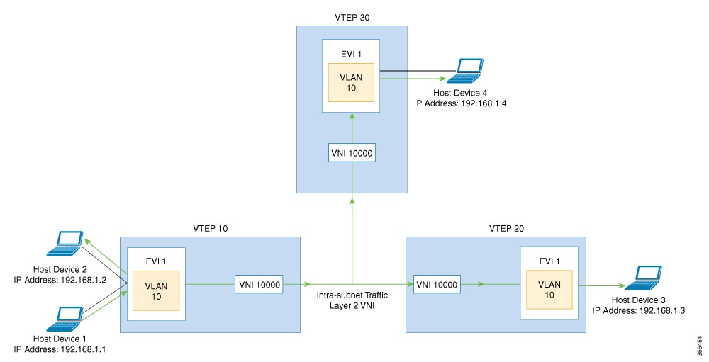
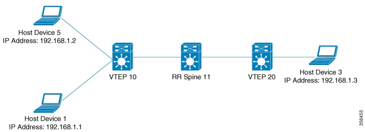


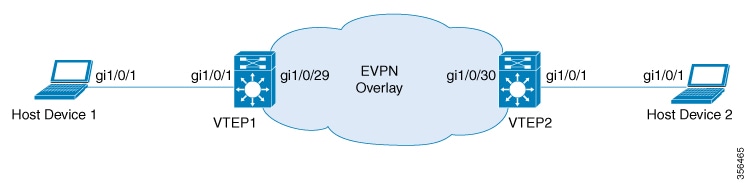
 Feedback