Removing and Replacing a Fan Module
The fan module can be removed and replaced only on a CGP-OLT-8T.
Installation Guidelines
Observe these guidelines when removing or installing a fan module:
-
Do not force the fan module into the slot. This can damage the pins on the device if they are not aligned with the module.
-
A fan module that is only partially connected to the device can disrupt the system operation.
-
The device supports hot swapping of the fan module. You can remove and replace the module without interrupting normal device operation.
 Warning |
Only trained and qualified personnel should be allowed to install, replace, or service this equipment. Statement 1030 |
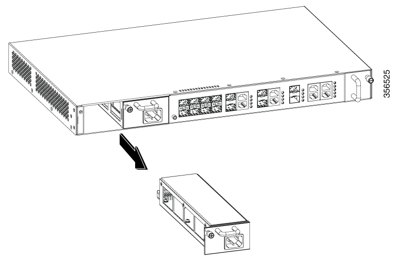
Removing the Fan Module
Before you begin
-
Ensure that you have the following tools and accessories available:
-
Phillips head screwdriver
-
Antistatic mat
-
Procedure
| Step 1 |
Use the Phillips head screwdriver and loosen the captive installation screw on the fan module of the OLT. 
|
||||
| Step 2 |
Grasp the fan module handle and slide the fan module half-way out of the bay. Gently move it from side to side, if necessary, to unseat it from the OLT. |
||||
| Step 3 |
Place your other hand underneath to support the bottom of the fan module and then remove the fan module completely.  |
What to do next
Set the removed fan module aside and proceed with the task of installing the replacement or spare fan module.
Installing a Fan Module
Before you begin
Procedure
| Step 1 |
Remove the replacement fan module from the shipping packaging. |
||
| Step 2 |
Install the fan module in the fan slot by firmly pushing it into the slot and applying pressure to the end of the module and not the extraction handles.
|
||
| Step 3 |
Insert the captive installation screw on the front panel of the fan module. Use the Phillips head screwdriver and tighten the captive installation screw on the fan module. |


 Feedback