- Overview
- Switch Models
- Front-Panel Description
Overview
This chapter describes the Cisco Industrial Ethernet (IE) 3000 switch, hereafter referred to as the switch, and covers these topics:
Overview
The Cisco IE 3000 switch provides a rugged and secure switching infrastructure for harsh environments. It is suitable for industrial Ethernet applications, including factory automation, intelligent transportation systems (ITSs), substations, and other deployments in harsh environments.
You can connect these switches to office networking devices like Cisco IP Phones, Cisco Wireless Access Points workstations, and other devices such as servers, routers, and other switches. In industrial environments, you can connect any Ethernet-enabled industrial communication devices, including programmable logic controllers (PLCs), human-machine interfaces (HMIs), drives, sensors, traffic signal controllers, and intelligent electronic devices (IEDs).
You can mount the switch on a DIN rail in an industrial enclosure, on a wall or panel, and with some restrictions, in a standard 19-inch rack. Its components are designed to withstand extremes in temperature, vibration, and shock that are common in an industrial environment.

Note![]() The switch does not have cooling fans.
The switch does not have cooling fans.
Switch Models
Table 1-1 describes the switch and the expansion modules. The Cisco IE-3000-4TC and
the Cisco IE-3000-8TC are the switch models, and the Cisco IEM-3000-8TM and the
Cisco IEM-3000-8FM are expansion modules that you can connect to increase the number of ports. For instructions on how to connect the expansion modules to the switch, see the “Adding Modules to the Switch” section.
4 10/100BASE-T Ethernet ports and 2 dual-purpose ports, each with a 10/100/1000BASE-T copper port and an SFP (small form-factor pluggable) module slot |
|
4 10/100BASE-T Ethernet ports and 2 dual-purpose ports (supports the IP services software feature set) |
|
8 10/100BASE-T Ethernet ports and 2 dual-purpose ports (supports the |
|
|
|
|
Expansion module with 8 100BASE-FX fiber-optic Ethernet ports |
|
Cisco IEM-3000-4PC1 |
|
Front-Panel Description
This section describes the front panel and includes these sections:
The switch front panel contains the ports, the LEDs, and the power and relay connectors. Figure 1-1 to Figure 1-6 show the switch and expansion module front panels.
Figure 1-1 Cisco IE-3000-8TC Switch

1 |
4 |
||
2 |
5 |
||
3 |
Figure 1-2 Cisco IE-3000-4TC Switch

1 |
4 |
||
2 |
5 |
||
3 |
Figure 1-3 Cisco IEM-3000-8TM Expansion Module

1 |
Figure 1-4 Cisco IEM-3000-8FM Expansion Module

1 |
Figure 1-5 Cisco IEM-3000-4SM Expansion Module
|
|
|

Figure 1-6 Cisco IEM-3000-8SM Expansion Module
|
|
|

Figure 1-7 Cisco IEM-3000-4PC PoE Expansion Module

|
|
|
||
|
|
|
Figure 1-8 Cisco IEM-3000-4PC-4TC PoE Expansion Module

|
|
|
||
|
|
|
10/100 Ports
You can set the 10/100 ports to operate at 10 or 100 Mb/s in full-duplex or half-duplex mode. You can also set these ports for speed and duplex autonegotiation in compliance with IEEE 802.3AB. (The default setting is autonegotiate.) When set for autonegotiation, the port senses the speed and duplex settings of the attached device and advertises its own capabilities. If the connected device also supports autonegotiation, the switch port negotiates the best connection (that is, the fastest line speed that both devices support and full-duplex transmission if the attached device supports it) and configures itself accordingly. In all cases, the attached device must be within 328 feet (100 meters). 100BASE-TX traffic requires Category 5 cable. 10BASE-T traffic can use Category 3 or Category 4 cables.
When connecting the switch to workstations, servers, routers, and Cisco IP Phones, be sure that the cable is a straight-through cable.
For copper ports, you can use the mdix auto interface configuration command in the command-line interface (CLI) to enable the automatic medium-dependent interface crossover (auto-MDIX) feature. When the auto-MDIX feature is enabled, the switch detects the required cable type for copper Ethernet connections and configures the interfaces accordingly. For configuration information for this feature, see the switch software configuration guide or the switch command reference.
Dual-Purpose Ports
A dual-purpose port can be configured as either a 10/100/1000 port or as an SFP module port. Only one port can be active at a time. If both ports are connected, the SFP module port has priority.
You can set the 10/100/1000 ports to operate at 10, 100, or 1000 Mb/s in full-duplex or half-duplex mode. You can configure them as fixed 10, 100, or 1000 Mb/s (Gigabit) Ethernet ports and can configure the duplex setting. (See the switch software configuration for more information.)
You can use Gigabit Ethernet SFP modules to establish fiber-optic connections to other switches. These transceiver modules are field-replaceable, providing the uplink interfaces when inserted in an SFP module slot. You use fiber-optic cables with LC connectors to connect to a fiber-optic SFP module.
For more information about these SFP modules, see the “SFP Modules” section, your SFP module documentation or the release note for your switch software.
SFP Modules
The switch Ethernet SFP modules provide connections to other devices. These field-replaceable transceiver modules provide the uplink interfaces.The modules have LC connectors for fiber-optic connections or RJ-45 connectors for copper connections. You can use any combination of the supported SFP modules listed in Table 1-2 .
|
|
|
|---|---|
For the most up-to-date list of supported SFP models for Cisco Industrial Ethernet switches, see http://www.cisco.com/en/US/docs/interfaces_modules/transceiver_modules/compatibility/matrix/OL_6981.html#wp138176
For information about SFP modules, see your SFP module documentation and the “Installing and Removing SFP Transceivers” section. For cable specifications, see Appendix C, “Cable and Connectors.”
100BASE-FX Ports
The IEEE 802.3u 100BASE-FX ports provide full-duplex 100 Mb/s connectivity over multimode fiber (MMF) cables. These ports use a small-form-factor fixed (SFF) fiber-optic transceiver module that accepts a dual LC connector. The cable can be up to 1.24 miles (2 km) in length.
100BASE-X Ports
The IEEE 802.3u 100BASE-X ports provide full-duplex 100 Mb/s connectivity over both single-mode (SMF) and multimode fiber (MMF) cables. These ports use a small-form-factor pluggable (SFP) fiber-optic transceiver module that accepts a dual LC connector (except in the case of the GLC-FE-100BX-U and GLC-FE-100BX-D SFP transceivers). With the GLC-FE-100ZX SFP transceiver installed, cable runs of up to 49.6 miles (80 km) are supported.
PoE Ports
The IEM-3000-4PC and the IEM-3000-4PC-4TC expansion modules provide 10/100BASE-T PoE capability to the IE3000 base switch. Both expansion modules support up to 4 PoE (802.3af) or 4 PoE+ (802.3at) devices. The PoE expansion modules require a dedicated power supply for PoE power.
Power and Relay Connector
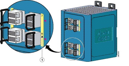
You connect the DC power and alarm signals to the switch through two front panel connectors. One connector provides primary DC power (supply A) and the major alarm signal, and a second connector (supply B) provides secondary power and the minor alarm signal. The two connectors are physically identical and are in the upper left side of the front panel. See Figure 1-2.
The switch accessory pack includes the mating power and relay connectors. These connectors provide screw terminals for terminating the DC power and alarm wire and the connector plugs into the power and relay receptacles on the front panel. The positive DC power connection is labeled V, and the return connection is labeled RT (see Figure 1-9).
Figure 1-9 Power and Relay Connector

The switch can operate with a single power source or with dual power sources. When both power sources are operational, the switch draws power from the DC source with the higher voltage. If one of the two power sources fail, the other continues to power the switch.
The power and relay connectors also provide an interface for two independent alarm relays: the major and the minor alarms. The relays can be activated for environmental, power supply, and port status alarm conditions and can be configured to indicate an alarm with either open or closed contacts. The relay itself is normally open, so under power failure conditions, the contacts are open. From the CLI, you can associate any alarm condition with one or with both alarm relays.
Alarm relays often control an external alarm device, such as a bell or a light. To connect an external alarm device to the relay, you must connect two relay contact wires to complete an electrical circuit. Both alarm terminals on the power and relay connector are labeled A, and you can connect them without regard to polarity.
See the switch software configuration guide for instructions on configuring the alarm relays.
For more information about the power and relay connector, see Appendix C, “Cable and Connectors.”
You can get replacement power and relay connectors (PWR-IE3000-CNCT=) by calling Cisco Technical Support.
Console Port
You can connect a switch to a PC through the console port and the supplied RJ-45-to-DB-9 adapter cable. If you want to connect a switch to a terminal, you need to provide an RJ-45-to-DB-25 female DTE adapter. You can order a kit (part number ACS-DSBUASYN=) with that adapter from Cisco Systems. For console-port and adapter-pinout information, see the “Two Twisted-Pair Cable Pinouts” section.
LEDs
You can use the LEDs to monitor the switch status, activity, and performance. Figure 1-10 to Figure 1-13 show the front panel LEDs, and the following sections describe them.
All LEDs are visible through the GUI management applications—the Cisco Network Assistant application for multiple switches and the device manager GUI for a single switch. The switch software configuration guide describes how to use the CLI to configure and to monitor individual switches and switch clusters.
Figure 1-10 LEDs on the Cisco IE 3000 Switch

1 |
5 |
||
2 |
6 |
||
3 |
7 |
||
4 |
8 |
Figure 1-11 LEDs on the Cisco IEM-3000-8TM Module

1 |
Figure 1-12 LEDs on the Cisco IEM-3000-8FM Module
1 |

Figure 1-13 LEDs on the Cisco IEM-3000-8SM Module
|
|
|
Note![]() The port numbering sequence is the same for the IEM-3000-4SM expansion module.
The port numbering sequence is the same for the IEM-3000-4SM expansion module.
The LED arrangement on the IEM-3000-4PC PoE expansion module is similar to the LED arrangement on the IEM-3000-4PC-4TC PoE expansion module except that the IEM-3000-4PC module does not have the four additional non-PoE ports with their associated port LEDs.
Setup LED
The Setup LED displays the express setup mode for the initial configuration. Table 1-3 lists the LED colors and their meanings.
System LED
The System LED shows whether the system is receiving power and is functioning properly.
Table 1-4 lists the system LED colors and their meanings.
Alarm LED
Table 1-5 lists the alarm LED colors and their meanings.
Power Status LED
The switch can operate with one or two DC power sources. Each DC input has an associated LED that shows the status of the corresponding DC input. If power is present on the circuit, the LED is green. If power is not present, the LED color depends on the alarm configuration. If alarms are configured, the LED is red when power is not present; otherwise, the LED is off.
If the switch has dual power sources, the switch draws power from the power source with the higher voltage. If the one of the DC sources fails, the alternate DC source powers the switch, and the corresponding power status LED is green. The power status for the failed DC source is either off or red, depending on the alarm configuration.
Table 1-6 lists the power status LED colors and meanings.
Power is not present on the circuit, or the system is not powered up. |
|
Power is not present on the associated circuit, and the power supply alarm is configured. |
Note![]() The Pwr A and Pwr B LEDs show that power is not present on the switch if the power input drops below the low valid level. The power status LEDs only show that power is present if the voltage at the switch input exceeds the valid level. The difference, or hysteresis, ensures that the power status LEDs do not oscillate at values near 18 V.
The Pwr A and Pwr B LEDs show that power is not present on the switch if the power input drops below the low valid level. The power status LEDs only show that power is present if the voltage at the switch input exceeds the valid level. The difference, or hysteresis, ensures that the power status LEDs do not oscillate at values near 18 V.
For information about the power LED colors during the power-on self-test (POST), see the “Verifying Switch Operation” section.
10/100 Port Status LEDs
Each 10/100 port has a port status LED, also called a port LED, as shown in Figure 1-10, Figure 1-11, and Figure 1-12. Table 1-7 displays LED information about the switch and the individual ports.
100Base-FX Port Status LEDs
These LEDs display information about the individual ports. See Table 1-8 .
A link blocked by Spanning Tree Protocol (STP) is sending or receiving data. |
|
Dual-Purpose Port LEDs
Figure 1-14 shows the LEDs on a dual-purpose port. You can configure each port as either a 10/100/1000 port through the RJ-45 connector or as an SFP module, but not both at the same time. The LEDs show how the port is being used (Ethernet or SFP module).
The LED colors have the same meanings as described in Table 1-7 .
Figure 1-14 Dual-Purpose Port LEDs
1 |
3 |
||
2 |
4 |

100BASE-X SFP Port LEDs
The 100BASE-X SFP port LEDs are located on the two SFP expansion modules. The LED colors have the same meanings as described in Table 1-7 .
PoE Status LED
The PoE status LED on the front panel of the IEM-3000-4PC and the IEM-3000-4PC-4TC PoE expansion modules displays the functionality and status of the PoE ports. The LED colors and meanings are listed in Table 1-9 .

10/100BASE-T PoE and Non-PoE Port LEDs
The 10/100BASE-T PoE and non-PoE port status LEDs on the front panel of the IEM-3000-4PC and the IEM-3000-4PC-4TC PoE expansion modules display the functionality and status of the individual ports on the expansion modules.
|
|
|
|---|---|
Link is up and there is data transfer in progress on the port. |
|
Compact Flash Memory Card
The switch supports a compact flash memory card that makes it possible to replace a failed switch without reconfiguring the new switch. The slot for the compact flash memory card is on the bottom of the switch. See .
Note![]() For more information on inserting and removing the compact flash memory card, see the “Installing or Removing the Compact Flash Memory Card” section.
For more information on inserting and removing the compact flash memory card, see the “Installing or Removing the Compact Flash Memory Card” section.
Figure 1-15 Compact Flash Memory Card Slot

Note![]() You can obtain replacement flash memory cards (CF-IE3000=) by calling Cisco Technical Support.
You can obtain replacement flash memory cards (CF-IE3000=) by calling Cisco Technical Support.
Rear-Panel Description
The rear panel of the switch, modules, and power converter have latches for installation on either a DIN rail or a wall. See Figure 1-16. The latches slide outward to position the switch over a DIN rail and slide inward to secure the switch to a DIN rail. The feet stabilize the switch when it is mounted on the wall.
Figure 1-16 Cisco IE 3000 Switch Rear Panel

1 |
2 |
Power Converter (Optional)
The switch can be used with an optional AC/DC power converter. The power converter (PWR-IE3000-AC) can supply 24-VDC power to one switch and up to two modules. The power converter is mounted on the side of a switch and provides power to the switch through a preassembled power cable.
Note![]() The power converter (PWR-IE3000-AC=) is sold separately.
The power converter (PWR-IE3000-AC=) is sold separately.
You can get a replacement power cable (PWR-IE3000-CLP=) by calling Cisco Technical Support.
For installation and connection procedures for the power converter, see the “Connecting the Switch to the Power Converter” section.
Figure 1-17 displays the power converter.
Figure 1-17 Cisco IE 3000 Switch AC/DC Power Converter
1 |
3 |
||
2 |

AC-Input Power Supply (Optional)
A 50 W AC-input power supply is available as an option for the IE 3000 switch. The power supply comes in two styles:
- PWR-IE50W-AC—An AC-input power supply with a terminal block connector for the source AC cable.
- PWR-IE50W-AC-IEC— An AC-input power supply with an IEC C14 appliance connector for a detachable AC power cord.
Figure 1-18 shows the AC-input power supply.
The power supply is designed to operate from source AC range of 85 to 264 VAC (115 VAC nominal at 60 Hz or 230 VAC nominal at 50 Hz) and provides 24 VDC to one switch and up to two modules. The power supply attaches to the side of a switch and provides power to the switch through a preassembled power cable (PWR-IE3000-CLP=).
Figure 1-18 AC-Input Power Supply (PWR-IE50W-AC= Shown)

|
|
|
Source AC terminal block (Cover shown installed) Note The source AC terminal block shown in the illustration is replaced by an IEC C14 appliance connector on the PWR-50W-AC-IEC= power supply. |
|
|
|
|
Management Options
The switch supports these management options:
Cisco Network Assistant is a PC-based network management GUI application optimized for LANs of small and medium-sized businesses. Through a GUI, users can configure and manage switch clusters or standalone switches. Cisco Network Assistant is available at no cost and can be downloaded from this URL:
http://www.cisco.com/en/US/products/ps5931/tsd_products_support_series_home.html
For information on starting the Cisco Network Assistant application, see the Getting Started with Cisco Network Assistant guide on Cisco.com.
You can use the device manager, which is in the switch memory, to manage individual and standalone switches. This web interface offers quick configuration and monitoring. You can access the device manager from anywhere in your network through a web browser. For more information, see the getting started guide and the device manager online help.
The switch CLI is based on Cisco IOS software and is enhanced to support desktop-switching features. You can fully configure and monitor the switch. You can access the CLI either by connecting your management station directly to the switch management port, or a console port, or by using Telnet from a remote management station. See the switch command reference on Cisco.com for more information.
The CiscoWorks device-management application displays the switch image that you can use to set configuration parameters and to view the switch status and performance information. The CiscoView application, which you purchase separately, can be a standalone application or part of a Simple Network Management Protocol (SNMP) platform. See the CiscoView documentation for more information.
You can manage switches from a SNMP-compatible management station that is running platforms such as HP OpenView or SunNet Manager. The switch supports a comprehensive set of Management Information Base (MIB) extensions and four Remote Monitoring (RMON) groups. See the switch software configuration guide on Cisco.com and the documentation that came with your SNMP application for more information.
The Common Industrial Protocol (CIP) management objects are supported. The Cisco IE 3000 can be managed by CIP-based management tools, allowing the user to manage an entire industrial automation system with one tool.
Network Configurations
See the switch software configuration guide on Cisco.com for network configuration concepts and examples of using the switch to create dedicated network segments and interconnecting the segments through Gigabit Ethernet connections.
 Feedback