Layer 2 Network Address Translation

Layer 2 Network Address Translation

One-to-one Layer 2 NAT (Network Address Translation) is a service that allows the assignment of a unique public IP address to an existing private IP address (end device). The assignment enables the end device to communicate on both the private and public subnets. This service is configured in a NAT-enabled device and is the public “alias” of the IP address that is physically programmed on the end device. This is typically represented by a table in the NAT device.

Layer 2 NAT uses a table to translate IPv4 addresses both public-to-private, and private-to-public at line rate. Layer 2 NAT is a hardware-based implementation that provides the same high level of (bump-on-the-wire) wire-speed performance. This implementation also supports multiple VLANs through the NAT boundary for enhanced network segmentation.

In the following example, Layer 2 NAT translates addresses between sensors on a 192.168.1.x network and a line controller on a 10.1.1.x network.

  1. The 192.168.1.x network is the inside/internal IP address space and the 10.1.1.x network is the outside or external IP address space.

  2. The sensor at 192.168.1.1 sends a ping request to the line controller by using an “inside” address, 192.168.1.100.

  3. Before the packet leaves the internal network, Layer 2 NAT translates the source address (SA) to 10.1.1.1 and the destination address (DA) to 10.1.1.100.

  4. The line controller sends a ping reply to 10.1.1.1.

  5. When the packet is received on the internal network, Layer 2 NAT translates the source address to 192.168.1.100 and the destination address to 192.168.1.1.

Figure 1. Translating Addresses Between Networks

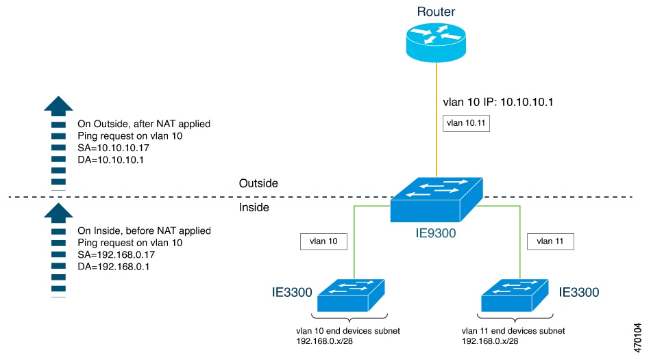
For large numbers of nodes, you can quickly enable translations for all devices in a subnet. In the scenario shown in the following figure, addresses from Inside Network 1 can be translated to outside addresses in the 10.1.1.0/28 subnet, and addresses from Inside Network 2 can be translated to outside addresses in the 10.1.1.16/28 subnet. All addresses in each subnet can be translated with one command. The benefit of using subnet-based translations saves in Layer L2 NAT rules. The switch has limits on the number of Layer 2 NAT rules. A rule with a subnet allows for multiple end devices to be translated with a single rule.

Figure 2. Inside-Outside Address Translation
Diagram of inside-outside address translation

The following figure shows a Cisco Catalyst IE9300 Rugged Series Switch at the aggregation layer forwarding Ethernet packets based on Layer 2 MAC Addresses. In this example, the router is the Layer 3 gateway for all subnets and VLANs.

The L2NAT instance definitions use the network command to define a translated row for multiple devices in the same subnet. In this the case, it’s a /28 subnet with last byte in the IP address starting with 16 and ending with 31. The gateway for the VLAN is the router with last byte of the IP address ending with .1. An outside host translation is provided for the router. The network command in the Layer 2NAT definition translates a subnet’s worth of host with a single command, saving on Layer 2 NAT translation records.

The Gi1/0/25 uplink interface has Layer 2NAT translation instances for vlan10 and vlan 11 subnets. Interfaces can support multiple Layer 2 NAT instance definitions.

The downstream Cisco Catalyst IE3300 Rugged Series Switches are examples of access layer switches which do not perform L2NAT and rely on the upstream aggregation layer switch to do it.

Figure 3. NAT on the Cisco Catalyst IE9300 Rugged Series Switch
Diagram of NAT on the Cisco Catalyst IE9300 Rugged Series Switch

The following example shows the NAT configuration for the preceding diagram:


!
l2nat instance Subnet10-NAT
 instance-id 1
 permit all
 fixup all
 outside from host 10.10.10.1 to 192.168.0.1
 inside from network 192.168.0.0 to 10.10.10.16 mask 255.255.255.240
!
l2nat instance Subnet11-NAT
 instance-id 1
 permit all
 fixup all
 outside from host 10.10.11.1 to 192.168.0.1
 inside from network 192.168.0.0 to 10.10.11.16 mask 255.255.255.240
!
interface GigabitEthernet1/0/25
 switchport mode trunk
 l2nat Subnet10-NAT 10
 l2nat Subnet11-NAT 11
!
Interface vlan 1
  ip address 10.10.1.2
 

Guidelines and Limitations

The following list provides guidelines and limitations for using Layer 2 NAT with Cisco Catalyst IE9300 Rugged Series Switches.


Note


For scale information, see the section NAT Performance and Scalability in this guide.


  • Layer 2 NAT is supported for Cisco Catalyst IE9300 Rugged Series Switches in Cisco IOS XE Dublin 17.10.1 and later releases.

  • Layer 2 NAT is supported for Cisco Catalyst IE9300 Rugged Series Switches on standalone or stacked switches.

  • Layer 2 NAT is disabled by default; it becomes enabled when you configure it. See Configure Layer 2 NAT in this guide.

  • Layer 2 NAT applies only to unicast traffic. Untranslated unicast traffic, multicast traffic, and IGMP traffic are permitted.

  • Layer 2 NAT is supported only on the uplink ports (25-28) and available in both Network Essentials and Network Advantage licenses.

  • Layer 2 NAT supports one-to-one mapping between external and internal IP addresses.

  • Layer 2 NAT can be applied to uplink interfaces in access or trunk mode.

  • Only IPv4 addresses for Layer 2 traffic can be translated.

  • Supported subnet masks on inside network translation are /24, /25, /26, /27, /28, and /32 only.

  • Outside translation rule supports only host translations.

  • ARP does not work transparently across Layer 2 NAT; however, the switch changes the IP addresses embedded in the payload of IP packets for the protocols to work. Embedded IP addresses are not translated.

  • Statistics for debugging include the following statistics: entries for each translation, translated total ingress and egress for each instance, and for each interface. Also included are ARP fixup stats and the number of translations entries allocated in hardware.

  • Layer 2 NAT does not support one-to-many and many-to-one IP address mapping.

  • Layer 2 NAT cannot save on public IP addresses because public-to-private is a 1:1 translation. It is not 1:N NAT.

  • If you configure a translation for a Layer 2 NAT host, do not configure it as a DHCP client.

  • When translating an inside address to an outside address using Layer 2 NAT, ensure that the translated IP address is not accessible in the global network.

  • The management interface is behind the Layer 2 NAT function. Therefore this interface should not be on the private network VLAN. If it is on the private network VLAN, assign an inside address and configure an inside translation.

  • Because Layer 2 NAT is designed to separate outside and inside addresses, we recommend that you do not configure addresses of the same subnet as both outside and inside addresses.

  • Cisco Catalyst IE9300 Rugged Series Switch uplinks that support NAT instance configurations are Gig1/0/25 to Gig1/0/28.

  • Layer 2 NAT is only for Layer 2 traffic; do not use it for packets undergoing routing

  • Layer 2 NAT does not translate packets destined for CPU and packets coming from CPU. Management traffic should be on a different VLAN from the private network VLAN.

  • Layer 2 NAT counters are not based on ports. When the same Layer 2 NAT instance is applied to multiple interfaces, the corresponding Layer 2 NAT counters will be displayed for all those interfaces.

NAT Performance and Scalability

Layer 2 NAT translation and forwarding are performed in the hardware at line rate. The number of Layer 2NAT rules that are supported depends on the number of hardware entries that can be supported in hardware.

Scale depends on the number of inside/outside combinations. The following list provides scale examples.

  • An instance with only inside rules can have a total of 128 translation rules.

  • Multiple instances with one inside rule can have a total of 128 such instances applied to 128 different VLANs.

  • Multiple instances with one inside rule and one outside rule can have a maximum of 64 instances.

  • A single instance with one outside rule can have a maximum of 100 inside rules. The number of inside rules that can be supported reduces with increase in the outside rules.


Note


We recommended that you use network translation rules to save on the number of rules.


Configure Layer 2 NAT

You must configure Layer 2 NAT instances that specify the address translations. Attach Layer 2 NAT instances to physical Ethernet interfaces, and configure which VLAN or VLANs the instances will be applied to. Layer 2 NAT instances can be configured from management interfaces (CLI/SNMP). You can view detailed statistics about the packets that are sent and received. See the section Verify the Configuration in this guide.

To configure Layer 2 NAT, follow these steps. Refer to the examples in Basic Inside-to-Outside Communications: Example and Duplicate IP Addresses Example in this guide for more details.

Procedure


Step 1

Enter global configuration mode:

configure terminal

Step 2

Create a new Layer 2 NAT instance:

l2nat instance instance_name After creating an instance, you use this same command to enter the submode for that instance.

Step 3

Translate an inside address to an outside address:

inside from [host | range | network] original ip to translated ip [mask] number | mask

You can translate a single host address, a range of host addresses, or all the addresses in a subnet. Translate the source address for outbound traffic and the destination address for inbound traffic.

Step 4

Translate an outside address to an inside address:

outside from [host | range | network ] original ip to translated ip [mask ] number | mask

You can translate a single host address, a range of host addresses, or the addresses in a subnet. Translate the destination address for outbound traffic and the source address for inbound traffic.

Step 5

Exit config-l2nat mode:

exit

Step 6

Access interface configuration mode for the specified interface (uplink ports only on the IE 3400):

interface interface-id

Step 7

Apply the specified Layer 2 NAT instance to a VLAN or VLAN range. If this parameter is missing, the Layer 2 NAT instance applies to the native VLAN.

l2nat instance_name [vlan | vlan_range ]

Step 8

Exit interface configuration mode:

end


Verify the Configuration

Procedure


Perform the following commands to verify the Layer 2 NAT configuration.

Command

Purpose

show l2nat instance

Displays the configuration details for a specified Layer 2 NAT instance.

show l2nat interface

Displays the configuration details for Layer 2 NAT instances on one or more interfaces.

show l2nat statistics

Displays the Layer 2 NAT statistics for all interfaces.

show l2nat statistics interface

Displays the Layer 2 NAT statistics for a specified interface.

debug l2nat

Enables showing real-time Layer 2 NAT configuration details when the configuration is applied.

show platform hardware fed switch 1 fwd-asic resource tcam table pbr record 0 format 0 -

Displays the hardware entries.

-show platform hardware fed switch active fwd-asic resource tcam utilization | in PBR

Displays the hardware resource utilization.

The following is an example of output of the show l2nat instance and the show l2nat statistics commands:
switch#show l2nat instance 
l2nat instance test
fixup  : all
outside from host    10.10.10.200 to 192.168.1.200
inside  from host    192.168.1.1 to 10.10.10.1
l2nat instance test2
fixup  : all
inside  from host    1.1.1.1 to 2.2.2.2
outside from host    2.2.2.200 to 1.1.1.200

Switch#show l2nat interface 
FOLLOWING INSTANCE(S) AND VLAN(s) ATTACHED TO ALL INTERFACES
==============================================================
l2nat Gi1/0/27 test 
==============================================================

Switch#show l2nat statistics 

STATS FOR INSTANCE: test (IN PACKETS)

TRANSLATED STATS (IN PACKETS)
=============================================================================
INTERFACE DIRECTION VLAN   TRANSLATED
Gi1/0/27     EGRESS    50    0         
Gi1/0/27     INGRESS   50    0         
-------------------------------------------------------------------------------

PROTOCOL FIXUP STATS (IN PACKETS)
=============================================================================
INTERFACE DIRECTION VLAN    ARP       
Gi1/0/27     REPLY    50    0      
Gi1/0/27     REQUEST   50    0
-------------------------------------------------------------------------------

PER TRANSLATION STATS (IN PACKETS)
=============================================================================
TYPE    DIRECTION SA/DA ORIGINAL IP     TRANSLATED IP   COUNT
OUTSIDE INGRESS   SA    10.10.10.200    192.168.1.200   0         
OUTSIDE EGRESS    DA    192.168.1.200   10.10.10.200    0         
INSIDE  EGRESS    SA    192.168.1.1     10.10.10.1      0         
INSIDE  INGRESS   DA    10.10.10.1      192.168.1.1     0         
-------------------------------------------------------------------------------
=============================================================================

TOTAL TRANSLATIONS ENTRIES IN HARDWARE: 4
TOTAL INSTANCES ATTACHED : 1
=============================================================================
GLOBAL NAT STATISTICS
=============================================================================
Total Number of TRANSLATED NAT  Packets   = 0
Total Number of ARP      FIX UP Packets   = 0
=============================================================================
ad

Basic Inside-to-Outside Communications: Example

In this example, A1 must communicate with a logic controller (LC) that is directly connected to the uplink port. A Layer 2 NAT instance is configured to provide an address for A1 on the outside network (10.1.1.1) and an address for the LC on the inside network (192.168.1.250).

Figure 4. Basic Inside-to-Outside Communications
Diagram of inside-to-outside network communications

Now this communication can occur:

  1. A1 sends an ARP request: SA: 192.168.1.1DA: 192.168.1.250.

  2. Cisco Switch A fixes up the ARP request:SA:10.1.1.1DA: 10.1.1.200.

  3. LC receives the request and learns the MAC Address of 10.1.1.1.

  4. LC sends a response:SA: 10.1.1.200DA: 10.1.1.1.

  5. Cisco Switch A fixes up the ARP response:SA: 192.168.1.250DA: 192.168.1.1.

  6. A1 learns the MAC address for 192.168.1.250, and communication starts.


Note


Basic Inside-to-Outside Communications: Configuration

This section contains the steps to configure inside-to-outside communications as described in the preceding section. You create the Layer 2 NAT instance, add two translation entries, and then apply the instance to the interface. ARP fixups are enabled by default.

Before you begin

Read and understand the content in the section Basic Inside-to-Outside Communications: Example.

Procedure


Step 1

Enter configuration mode.

Example:

switch# configure 

Step 2

Create a new Layer 2 NAT instance called A-LC.

Example:

switch(config)# l2nat instance  A-LC 

Step 3

Translate A1’s inside address to an outside address.

Example:

switch(config-l2nat)# inside from host 192.168.1.1 to 10.1.1.1 

Step 4

Translate A2’s inside address to an outside address.

Example:

switch(config-l2nat)# inside from host 192.168.1.2 to 10.1.1.2 

Step 5

Translate A3’s inside address to an outside address.

Example:

switch(config-l2nat)# inside from host 192.168.1.3 to 10.1.1.3 

Step 6

Translate the LC outside address to an inside address.

Example:

switch(config-l2nat)# outside from host 10.1.1.200 to 192.168.1.250 

Step 7

Exit config-l2nat mode.

Example:

switch(config-l2nat)# exit 

Step 8

Access interface configuration mode for the uplink port.

Example:

witch(config)# interface Gi1/1 

Step 9

Apply this Layer 2 NAT instance to the native VLAN on this interface.

Example:

switch(config-if)# l2nat A-LC 

Note


For tagged traffic on a trunk, add the VLAN number when attaching the instance to an interface as follows:

l2nat instance vlan

Step 10

Return to privileged EXEC mode.

Example:

switch# end 

Duplicate IP Addresses Example

In this scenario, two machine nodes are preconfigured with addresses in the 192.168.1.x space. Layer 2 NAT translates these addresses to unique addresses on separate subnets of the outside network. In addition, for machine-to-machine communications, the Node A machines need unique addresses on the Node B space and the Node B machines need unique addresses in the Node A space.

Figure 5. Duplicate IP Addresses
  • Switch C needs an address in the 192.168.1.x space. When packets come into Node A or Node B, the 10.1.1.254 address of Switch C is translated to 192.168.1.254. When packets leave Node A or Node B, the 192.168.1.254 address of Switch C is translated to 10.1.1.254.

  • Node A and Node B machines need unique addresses in the 10.1.1.x space. For quick configuration and ease of use, the 10.1.1.x space is divided into subnets: 10.1.1.0, 10.1.1.16, 10.1.1.32, and so on. Each subnet can then be used for a different node. In this example, 10.1.1.16 is used for Node A, and 10.1.1.32 is used for Node B.

  • Node A and Node B machines need unique addresses to exchange data. The available addresses are divided into subnets. For convenience, the 10.1.1.16 subnet addresses for the Node A machines are translated to 192.168.1.16 subnet addresses on Node B. The10.1.1.32 subnet addresses for the Node B machines are translated to 192.168.1.32 addresses on Node A.

  • Machines have unique addresses on each network:

Table 1. Translated IP Addresses

Node

Address in Node A

Address in Outside Network

Address in Node B

Switch A network address

192.168.1.0

10.1.1.16

192.168.1.16

A1

192.168.1.1

10.1.1.17

192.168.1.17

A2

192.168.1.2

10.1.1.18

192.168.1.18

A3

192.168.1.3

10.1.1.19

192.168.1.19

Cisco Switch B network address

192.168.1.32

10.1.1.32

192.168.1.0

B1

192.168.1.33

10.1.1.33

192.168.1.1

B2

192.168.1.34

10.1.1.34

192.168.1.2

B3

192.168.1.35

10.1.1.35

192.168.1.3

Switch C

192.168.1.254

10.1.1.254

192.168.1.254

Duplicate IP Addresses Configuration: Switch A

This section provides the steps for configuring Layer 2 NAT to translate the duplicated IP address of one machine node in an inside network to a unique address on a subnet of an outside network. This procedure is for Switch A in the section Duplicate IP Addresses Example.

Before you begin

Read and understand the content in the section Duplicate IP Addresses Example.

Procedure


Step 1

Enter global configuration mode.

Example:

switch# configure 

Step 2

Create a new Layer 2 NAT instance called A-Subnet.

Example:

switch(config)# l2nat instance  A-Subnet 

Step 3

Translate the Node A machines’ inside addresses to addresses in the 10.1.1.16 255.255.255.240 subnet.

Example:

switch(config-l2nat)# inside from network 192.168.1.0 to 10.1.1.16 mask 255.255.255.240 

Step 4

Translate the outside address of Switch C to an inside address.

Example:

switch(config-l2nat)# outside from host 10.1.1.254 to 192.168.1.254 

Step 5

Translate the Node B machines’ outside addresses to their inside addresses.

Example:

switch(config-l2nat)# outside from host 10.1.1.32 to 192.168.1.32
outside from host 10.1.1.33 to 192.168.1.33
outside from host 10.1.1.34 to 192.168.1.34
outside from host 10.1.1.35 to 192.168.1.35

Step 6

Exits config-l2nat mode.

Example:

switch(config-l2nat)# exit 

Step 7

Access interface configuration mode for the uplink port.

Example:

switch(config)# interface Gi1/1 

Step 8

Apply this Layer 2 NAT instance to the native VLAN on this interface.

Example:

switch(config-if)# l2nat A-Subnet 

Note


For tagged traffic on a trunk, add the VLAN number when attaching the instance to an interface as follows:

l2nat instance vlan

Step 9

Return to privileged EXEC mode.

Example:

switch# end 

What to do next

Configure Layer 2 NAT to translate the duplicated IP address of Switch B in the section Duplicate IP Addresses Example. See Duplicate IP Addresses Configuration: Switch B.

Duplicate IP Addresses Configuration: Switch B

This section provides the steps for configuring Layer 2 NAT to translate the duplicated IP address of one machine node in an inside network to a unique address on a subnet of an outside network. This procedure is for Switch B in the section Duplicate IP Addresses Example.

Before you begin

Read and understand the content in the section Duplicate IP Addresses Example.

Procedure


Step 1

Enter global configuration mode.

Example:

switch# configure 

Step 2

Create a new Layer 2 NAT instance called B-Subnet.

Example:

switch(config)# l2nat instance  B-Subnet 

Step 3

Translate the Node B machines’ inside addresses to addresses in the 10.1.1.32 255.255.255.240 subnet.

Example:

switch(config-l2nat)# inside from network 192.168.1.0 to 10.1.1.32 255.255.255.240 

Step 4

Translate the outside address of Switch C to an inside address.

Example:

switch(config-l2nat)# outside from host 10.1.1.254 to  

Step 5

Translate the Node A machines’ outside addresses to their inside addresses.

Example:

switch(config-l2nat)# outside from host 10.1.1.16 to 192.168.1.16
outside from host 10.1.1.17 to 192.168.1.17
outside from host 10.1.1.18 to 192.168.1.18
outside from host 10.1.1.19 to 192.168.1.19

Step 6

Exit config-l2nat mode.

Example:

switch(config-l2nat)# exit 

Step 7

Access interface configuration mode for the uplink port.

Example:

switch(config)# interface Gi1/1 

Step 8

Apply this Layer 2 NAT instance to the native VLAN on this interface.

Example:

switch(config-if)# l2nat name1 

Note


For tagged traffic on a trunk, add the VLAN number when attaching the instance to an interface as follows:

l2nat instance vlan

Step 9

Show the configuration details for the specified Layer 2 NAT instance.

Example:

switch# show l2nat instance name1 

Step 10

Show Layer 2 NAT statistics.

Example:

switch# show l2nat statistics 

Step 11

Return to privileged EXEC mode.

Example:

switch# end