Resilient Ethernet Protocol
Resilient Ethernet Protocol (REP) is a Cisco proprietary protocol that provides an alternative to Spanning Tree Protocol (STP) to control network loops, handle link failures, and improve convergence time. REP controls a group of ports that are connected in a segment, ensures that the segment does not create any bridging loops, and responds to link failures within the segment. REP provides a basis for constructing more complex networks and supports VLAN load balancing.
 Note |
REP is supported in Cisco IOS XE Cupertino 17.9.x and later releases for Cisco Catalyst IE9300 Rugged Series Switches with the Network Essentials license. |
REP segment is a chain of ports that are connected to each other and configured with a segment ID. Each segment consists of standard (nonedge) segment ports and two user-configured edge ports. A switch can have no more than two ports that belong to the same segment, and each segment port can have only one external neighbor. A segment can go through a shared medium, but on any link, only two ports can belong to the same segment. REP is supported only on Trunk ports.
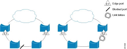
The following figure shows an example of a segment consisting of six ports spread across four switches. Ports E1 and E2 are configured as edge ports. When all ports are operational (as in the segment on the left), a single port is blocked, shown by the diagonal line. This blocked port is also known as the Alternate port (ALT port). When there is a failure in the network, the blocked port returns to the forwarding state to minimize network disruption.

The segment shown in the preceding figure is an open segment; there is no connectivity between the two edge ports. The REP segment cannot cause a bridging loop, and you can safely connect the segment edges to any network. All hosts connected to switches inside the segment have two possible connections to the rest of the network through the edge ports, but only one connection is accessible at any time. If a failure occurs on any segment or on any port on a REP segment, REP unblocks the ALT port to ensure that connectivity is available through the other gateway.
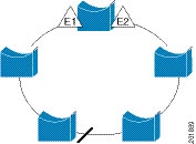
The segment in the following figure is a closed segment, also known as Ring Segment, with both edge ports located on the same router. With this configuration, you can create a redundant connection between any two routers in the segment.

REP segments have the following characteristics:
-
If all ports in a segment are operational, one port (referred to as the ALT port) is in the blocked state for each VLAN. If VLAN load balancing is configured, two ALT ports in the segment control the blocked state of VLANs.
-
If a port is not operational, and causes a link failure, all ports forward traffic on all VLANs to ensure connectivity.
-
In case of a link failure, alternate ports are unblocked as quickly as possible. When the failed link is restored, a logically blocked port per VLAN is selected with minimal disruption to the network.
You can construct almost any type of network that is based on REP segments.
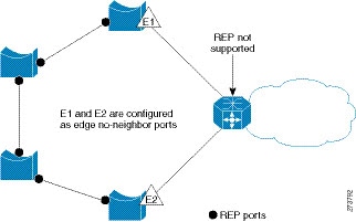
In access ring topologies, the neighboring switch might not support REP as shown in the following figure. In this case, you can configure the non-REP facing ports (E1 and E2) as edge no-neighbor ports. The edge no-neighbor port can be configured to send an STP topology change notice (TCN) towards the aggregation switch.

REP has these limitations:
-
You must configure each segment port; an incorrect configuration can cause forwarding loops in the networks.
-
REP can manage only a single failed port within the segment; multiple port failures within the REP segment cause loss of network connectivity.
-
You should configure REP only in networks with redundancy. Configuring REP in a network without redundancy causes loss of connectivity.
Link Integrity
REP does not use an end-to-end polling function between edge ports to verify link integrity. It implements local link failure detection. The REP Link Status Layer (LSL) detects its REP-aware neighbor and establishes connectivity within the segment. All the VLANs are blocked on an interface until the neighbor is detected. After the neighbor is identified, REP determines which neighbor port should become the alternate port and which ports should forward traffic.
Each port in a segment has a unique port ID. The port ID format is similar to that used by the spanning tree algorithm: a port number (unique on the bridge) associated to a MAC address (unique in the network). When a segment port is coming up, its LSL starts sending packets that include the segment ID and the port ID. The port is declared as operational after it performs a three-way handshake with a neighbor in the same segment.
A segment port does not become operational if:
-
No neighbor has the same segment ID.
-
More than one neighbor has the same segment ID.
-
A neighbor does not acknowledge a local port as a peer.
Each port creates an adjacency with its immediate neighbor. After the neighbor adjacencies are created, the ports negotiate with each other to determine the blocked port for the segment, which will function as the alternate port. All the other ports become unblocked. By default, REP packets are sent to a bridge protocol data unit-class MAC address. The packets can also be sent to a Cisco multicast address, which is used only to send blocked port advertisement (BPA) messages when there is a failure in the segment. The packets are dropped by the devices not running REP.
Fast Convergence
REP runs on a physical link basis and not on a per-VLAN basis. Only one hello message is required for all the VLANs, and this reduces the load on the protocol. We recommend that you create VLANs consistently on all the switches in a given segment and configure the same allowed VLANs on the REP trunk ports. To avoid the delay introduced by relaying messages in software, REP also allows some packets to be flooded to a regular multicast address. These messages operate at the hardware flood layer (HFL) and are flooded to the entire network, not just the REP segment. Switches that do not belong to the segment treat them as data traffic. You can control flooding of these messages by configuring an administrative VLAN for the entire domain or for a particular segment.
VLAN Load Balancing
One edge port in the REP segment acts as the primary edge port; and another as the secondary edge port. It is the primary edge port that always participates in VLAN load balancing in the segment. REP VLAN balancing is achieved by blocking some VLANs at a configured alternate port and all the other VLANs at the primary edge port. When you configure VLAN load balancing, you can specify the alternate port in one of three ways:
-
By entering the port ID of the interface. To identify the port ID of a port in the segment, enter the show interface rep detail interface configuration command for the port.
-
By entering the preferred keyword to select the port that you previously configured as the preferred alternate port with the rep segment segment-id preferred interface configuration command.
-
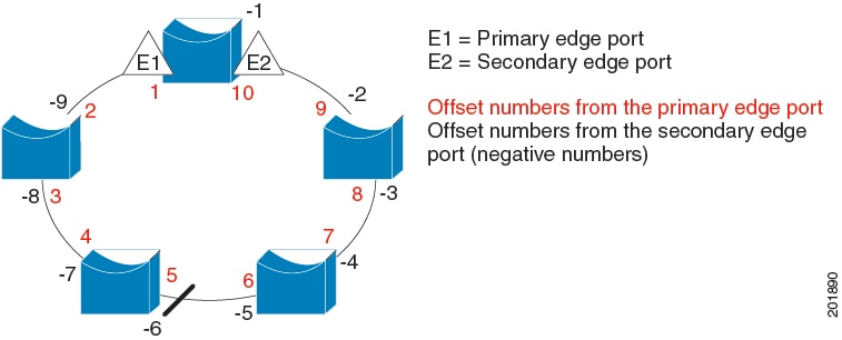
By entering the neighbor offset number of a port in the segment, which identifies the downstream neighbor port of an edge port. The neighbor offset number range is –256 to +256; a value of 0 is invalid. The primary edge port has an offset number of 1; positive numbers above 1 identify downstream neighbors of the primary edge port. Negative numbers indicate the secondary edge port (offset number -1) and its downstream neighbors.

Note
Configure offset numbers on the primary edge port by identifying a port’s downstream position from the primary (or secondary) edge port. Never enter an offset value of 1 because that is the offset number of the primary edge port.
The following figure shows neighbor offset numbers for a segment, where E1 is the primary edge port and E2 is the secondary edge port. The red numbers inside the ring are numbers offset from the primary edge port; the black numbers outside of the ring show the offset numbers from the secondary edge port. Note that you can identify all the ports (except the primary edge port) by either a positive offset number (downstream position from the primary edge port) or a negative offset number (downstream position from the secondary edge port). If E2 became the primary edge port, its offset number would then be 1 and E1 would be -1.
Figure 4. Neighbor Offset Numbers in a Segment 
When the REP segment is complete, all the VLANs are blocked. When you configure VLAN load balancing, you must also configure triggers in one of two ways:
-
Manually trigger VLAN load balancing at any time by entering the rep preempt segment segment-id privileged EXEC command on the switch that has the primary edge port.
-
Configure a preempt delay time by entering the rep preempt delay seconds interface configuration command. After a link failure and recovery, VLAN load balancing begins after the configured preemption time period elapses. Note that the delay timer restarts if another port fails before the time has elapsed.
 Note |
When VLAN load balancing is configured, it does not start working until triggered by either manual intervention or a link failure and recovery. |
When VLAN load balancing is triggered, the primary edge port sends out a message to alert all the interfaces in the segment about the preemption. When the secondary port receives the message, the message is sent to the network to notify the alternate port to block the set of VLANs specified in the message and to notify the primary edge port to block the remaining VLANs.
You can also configure a particular port in the segment to block all the VLANs. Only the primary edge port initiates VLAN load balancing, which is not possible if the segment is not terminated by an edge port on each end. The primary edge port determines the local VLAN load-balancing configuration.
Reconfigure the primary edge port to reconfigure load balancing. When you change the load-balancing configuration, the primary edge port waits for the rep preempt segment command or for the configured preempt delay period after a port failure and recovery, before executing the new configuration. If you change an edge port to a regular segment port, the existing VLAN load-balancing status does not change. Configuring a new edge port might cause a new topology configuration.
Spanning Tree Interaction
REP does not interact with STP, but it can coexist. A port that belongs to a segment is removed from spanning tree control and STP BPDUs are not accepted or sent from segment ports. Therefore, STP cannot run on a segment.
To migrate from an STP ring configuration to REP segment configuration, begin by configuring a single port in the ring as part of the segment and continue by configuring contiguous ports to minimize the number of segments. Each segment always contains a blocked port, so multiple segments means multiple blocked ports and a potential loss of connectivity. When the segment has been configured in both directions up to the location of the edge ports, you then configure the edge ports.
Resilient Ethernet Protocol (REP) Negotiated
 Note |
REP Negotiated works only on uplink ports. |
REP and Spanning Tree Protocol (STP) are two different loop avoidance protocols. REP has certain advantages over STP in terms of convergence time. REP can be configured to run in a ring topology in such a way that it can provide the redundant path in case of a single link failure in the ring.
Cisco switches are STP enabled by default. If a switch that is STP enabled is inserted in an already running REP ring (for addition of a new node or replacement of existing node) the following conditions apply:
-
The new switch will cause a break in the REP ring.
-
The new switch will not be able to communicate over the ring until it is configured to be part of the REP ring.
The REP Negotiated feature tries to solve these issues by negotiating the REP status with the peers. The following table identifies when REP Negotiation events will trigger and the action to take. There are two events: both peers are negotiating, and neither peer is negotiating.
|
SELF REP Negotiated |
PEERS REP Negotiated |
Event Triggered |
Action |
|---|---|---|---|
|
True |
True |
REPN |
Configure REP |
|
True |
False |
REPNN |
Configure STP |
|
False |
X |
REPNN |
Remain in STP |
This feature depends on 3 different protocols to get the required data and decide the correct configuration. The different protocols involved, and their purpose is given below:
-
STP : By default, STP is enabled on all the ports on the Cisco Switch.
-
REP : The customer network is configured to form a REP ring to provide better convergence time and redundancy.
-
Cisco Discovery Protocol (CDP) : The feature depends on user defined TLVs sent through CDP messages to negotiate the correct (STP or REP) configuration for the interface.
REP Ports
REP segments consist of Failed, Open, or Alternate ports:
-
A port configured as a regular segment port starts as a failed port.
-
After the neighbor adjacencies are determined, the port transitions to alternate port state, blocking all the VLANs on the interface. Blocked-port negotiations occur, and when the segment settles, one blocked port remains in the alternate role and all the other ports become open ports.
-
When a failure occurs in a link, all the ports move to the Failed state. When the Alternate port receives the failure notification, it changes to the Open state, forwarding all the VLANs.
A regular segment port converted to an edge port, or an edge port converted to a regular segment port, does not always result in a topology change. If you convert an edge port into a regular segment port, VLAN load balancing is not implemented unless it has been configured. For VLAN load balancing, you must configure two edge ports in the segment.
A segment port that is reconfigured as a spanning tree port restarts according to the spanning tree configuration. By default, this is a designated blocking port. If PortFast is configured or if STP is disabled, the port goes into the forwarding state.


 Feedback