Managing a Stack of Switches
Switches can either function on their own, or they can be connected into a stack of switches. By default, a device is always stackable, but has no stack port. All ports on the switches are network ports by default. You can look at a switch without any stack port as the active unit in a stack of only itself. You can also look at a switch without any stack port as a standalone switch. To stack two or more devices, reconfigure the desired network ports as stack ports in the switches and connect the switches with the resulting stack ports in a ring or chain topology.
The switches (units) in a stack are connected through stack ports. These switches are then collectively managed as a single logical switch. In some cases, stack ports can become members in Link Aggregation Groups (LAGs) increasing the bandwidth of the stack port.
The stack is based on a model of a single active/standby and multiple members. A stack provides the following benefits:
-
Network capacity can be expanded or contracted dynamically. By adding a unit, the administrator can dynamically increase the number of ports in the stack while maintaining a single point of management. Similarly, units can be removed to decrease network capacity.
-
The stacked system supports redundancy in the following ways:
-
The standby unit becomes the active of the stack if the original active fails.
-
The stack system supports two types of topologies: chain and ring. In ring topology, if one of the stack ports fails, the stack continues to function in chain topology.
-
A process known as Fast Stack Link Failover is supported on the ports in a ring stack to reduce the duration of data packet loss when one of the stack ports link fails. Until the stack recovers to the new chain topology, a stack unit loops back the packets that are supposed to be sent through its failed stacking port, and transmits the looped back packets through its remaining stacking port to the destinations. During Fast Stack Link failover, the active/standby units remain active and functioning.
-
Types of Units in Stack
A stack consists of a maximum of eight units. A unit in a stack is one of the following types:
-
Active—The active unit’s ID must be either 1 or 2. The stack is managed through the active unit that manages itself, the stand by unit and the member units.
-
Stand by—If the active unit fails, the stand by unit assumes the active role(switchover). The stand by unit’s ID must be either 1 or 2.
-
Member—These units are managed by the active unit.
In order for a group of units to function as a stack, there must be an active-enabled unit. When the active-enabled unit fails, the stack continues to function as long as there is a stand by unit (the main unit that assumes the active role).If the stand by unit fails, in addition to the active unit, and the only functioning units are the member units. These also stop functioning after one minute. This means for example, that if after 1 minute, you plug in a cable to one of the member units that was running without an active, the link will not come up.
Backward Compatibility of Number of Units in Stack
The stackable switches support anywhere from four units to eight units. This varies based on the switch model. Upgrading from and earlier software release can be done without changing the configuration files. When a firmware version, which does not support the hybrid stack modes is loaded to the stack and the stack is rebooted, the stack reverts to Native Stack mode. When a device in Hybrid stack mode is loaded with a firmware version that does not support Hybrid stack mode, its system mode reverts to the default system mode. If a stack’s unit IDs were manually-configured, those units whose ID is greater than 4 are switched to auto numbering.
Stack Topology
The units in a stack can be connected in one of the following types of topologies:
-
Chain Topology—Each unit is connected to the neighboring unit, but there is no cable connection between the first and last unit.
-
Ring Topology—Each unit is connected to the neighboring unit. The last unit is connected to the first unit. The following shows a ring topology of an eight-unit stack:
A ring topology is more reliable than a chain topology. The failure of one link in a ring does not affect the function of the stack, whereas the failure of one link in a chain connection might cause the stack to be split.
Topology Discovery
A stack is established by a process called topology discovery. This process is triggered by a change in the up/down status of a stack port. The following are examples of events that trigger this process:
-
Changing the stack topology from a ring to a chain
-
Merging two stacks into a single stack
-
Splitting the stack
-
Inserting other member units to the stack, for instance because the units previously disconnected from the stack due to a failure. This can happen in a chain topology if a unit in the middle of the stack fails.
During topology discovery, each unit in a stack exchanges packets, which contain topology information. After the topology discovery process is completed, each unit contains the stack mapping information of all units in the stack.
Unit ID Assignment
After topology discovery is completed, each unit in a stack is assigned a unique unit ID. The unit ID is set in the System Mode and Stack Management page in one of the following ways:
-
Automatically (Auto) —The Unit ID is assigned by the topology discovery process. This is the default setting.
-
Manually—The unit ID is manually set to an integer from 1-8.
If you assign the same unit ID to two separate units, only one of them can join the stack with that unit ID. If auto numbering has been selected, the duplicate unit is assigned a new unit number. If auto numbering was not selected, the duplicate unit is shut down. The following shows a case where two units were manually assigned the same unit ID. Unit 1 does not join the stack and is shut down. It did not win the active selection process between the active-enabled units (1 or 2).

Active Selection Process
The active unit is selected from the active-enabled units (1 or 2). The factors in selecting the active unit are taken into account in the following priority:
-
Force Active—If Force Active is activated on a unit, it is selected.
-
System Up Time—The active-enabled units exchange up-time, which is measured in segments of 10 minutes. The unit with the higher number of segments is selected. If both units have the same number of time segments,and the unit ID of one of the units was set manually while the other unit’s unit ID was set automatically, the unit with the manually-defined unit ID is selected; otherwise the unit with the lowest unit ID is selected. If both units IDs are the same, the unit with the lowest MAC address is chosen.

Note
The up time of the stand by unit is retained when it is selected as active in the switch failover process.
-
Unit ID—If both units have the same number of time segments, the unit with the lowest unit ID is selected.
-
MAC Address—If both units IDs are the same, the unit with the lowest MAC address is chosen.
 Note |
For a stack to operate, it must have an active unit. An active unit is defined as the main unit that assumes the active role. The stack must contain a unit 1 and/or unit 2 after the active selection process. Otherwise, the stack and all its units are partially shut down, not as a complete power-off, but with traffic-passing capabilities halted |
Stack Changes
This section describes various events that can cause a change to the stack. A stack topology changes when one of the following occurs:
-
One or more units are connecting and/or disconnecting to and from the stack.
-
Any of its stack ports has a link up or down.
-
The stack changes between ring and chain formation.
When units are added or removed to and from a stack, it triggers topology changes, master election process, and/or unit ID assignment.
Connecting a New Unit
When a unit is inserted into the stack, a stack topology change is triggered. The unit ID is assigned (in case of auto numbering), and the unit is configured by the active unit.
One of the following cases can occur when connecting a new unit to an existing stack:
-
No duplicate unit IDs exist.
-
Units with user-defined IDs retain their unit ID.
-
Units with automatically-assigned IDs retain their unit ID.
-
Factory default units receive unit IDs automatically, beginning from the lowest available ID.
-
-
One or more duplicate unit IDs exist. Auto numbering resolves conflicts and assigns unit IDs. In case of manual numbering, only one unit retains its unit ID and the other(s) are shutdown.
-
The number of units in the stack exceeds the maximum number of units allowed. The new units that joined the stack are shut down, and a SYSLOG message is generated and appears on the master unit
The following shows an example of auto numbering when an active-enabled unit joins the stack. There are two units with unit ID = 1. The active selection process selects the best unit to be the active unit. The best unit is the unit with the higher uptime in segments of 10 minutes. The other unit is made the backup
Auto-numbered Active-enabled Unit
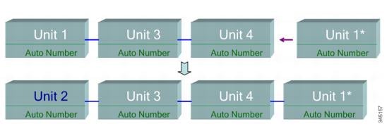
The following shows an example of auto numbering when a new unit joins thes tack. The existing units retain their ID. The new unit receives the lowest available ID.
Auto Number Unit

The following shows what happens when a user-assigned, active-enabled unit with Unit ID 1 joins a stack that already has an active unit with user-assigned unit ID1. The newer Unit 1 does not join the stack and is shutdown.
User-assigned Active-enabled Unit

Unit Failure in Stack
If the active unit fails, then the standby unit will take over the primary role and continues to operate the stack normally.
For the standby switch to be able to take the place of the active switch, both units remain on reserve at all times. When on reserve mode, the active switch and its standby switches are synchronized with a static configuration (contained in both the Startup and Running configuration files). The standby switch configuration file remains on the previous active switch.
Dynamic process-state information, such as the STP state table, dynamically-learned MAC addresses, dynamically-learned Smartport types, MAC Multicast tables, LACP, and GVRP are not synchronized. When an active switch is being configured, it synchronizes with the standby unit immediately. Synchronization is performed as soon as a command is executed. This is transparent.
When an active switch is being configured, it synchronizes the backup immediately. Synchronization is performed as soon as a command is executed. This is transparent.
If a unit is inserted into a running stack, and is selected as a standby unit, the active switch synchronizes it so that it has an up-to date configuration, and then generates a SYNC COMPLETE SYSLOG message. This is a unique SYSLOG message that appears only when standby is converging with the active unit, and looks like this: %DSYNCH-I-SYNCH_SUCCEEDED: Synchronization with unit 2 is finished successfully.
Active / Standby Switchover
When a active switch fails on the stack, a switchover occurs. The standby unit becomes the active, and all of its processes and protocol stacks are initialized to take responsibility for the entire stack. As a result, there is temporarily no traffic forwarding in this unit, but member units remain active.
 Note |
When STP is used and the ports are in link up, the STP port’s state is temporarily Blocking, and it cannot forward traffic or learn MAC addresses. This is to prevent spanning tree loops between active units. |
Member Unit Handling
While the standby unit becomes the active switch, the member units remain active and continue to forward packets based on the configuration from the original active switch. This minimizes data traffic interruption in units. After the standby unit has completed the transition to the active state, it initializes the member units one at a time by performing the following operations:
-
Clear and reset the configuration of the member unit to default (to prevent an incorrect configuration from the new active unit). As a result, there is no traffic forwarding on the member unit.
-
Apply related user configurations to the member unit.
-
Exchange dynamic information such as port STP state, dynamic MAC addresses, and link up/down status between the new active and member unit. Packet forwarding on the member unit resumes after the state of its ports are set to forwarding by the active switch according to STP.

Note
Packet flooding to unknown Unicast MAC addresses occurs until the MAC addresses are learned or relearned.
Reconnecting the Original Active Unit after Failover
After failover, if the original active switch is connected again, the active selection process is performed. If the original active switch (unit 1) is reselected to be the active unit, the current active switch (unit 2, which was the original backup unit) is rebooted and becomes the backup once again.
 Note |
During active unit failover, the uptime of the standby unit is retained. |
Software Auto Synchronization in a Stack
All units in the stack must run the same software version (firmware and boot code). Each unit in a stack automatically downloads firmware and boot code from the active unit if the firmware and/or boot code that the unit and the active are running is different. The unit automatically reboots itself to run the new version.
Stack Ports
All ports on the device are network (uplink) ports by default. To connect units, you must change the types of the ports to be used to connect the devices as stack ports. These ports are used to transfer data and protocol packets among the units
Stack Port Link Aggregation
When two neighboring units are connected, the stack ports connecting them are automatically assigned to a stack LAG. This feature enables increasing the stack bandwidth of the stack port beyond that of a single port. There can be up to two stack LAGs per unit.
The stack LAG can be composed of between two and up to the maximum number of stack ports depending on the unit type.
Stack Port States
Stack ports can be in one of the following states:
-
Down—Port operational status is down or stack port operational status is up, but traffic cannot pass on the port.
-
Active—Stack port was added to a stack LAG whose stack port operational status is up and traffic can pass on the port and it is a member of a stack LAG.
-
Standby—Stack port operational status is up and bidirectional traffic can pass on the port, but the port cannot be added to a stack LAG, and the port does not transmit traffic. Possible reasons for a port being in standby are:
-
Stack ports with different speeds are used to connect a single neighbor.
-
Backwards Compatibility
The following modes have been expanded in the current software version of the device. Care must be taken when using these features in previous software versions:
-
Stack Port LAG—If a unit whose software supports stack ports in LAGs is connected to a unit whose software does not support stack ports in LAGs, the stack port connecting the units is not made a member of the stack LAG. The units are connected through the stack ports, and the active stack unit copies its software to the other unit. The software copied depends on the unit which becomes the active unit.
-
Queues Mode—This mode can be changed from 4 QoS queues to 8 QoS queues. There is no issue when upgrading from previous software versions that did not support 8 queues, since the 4-queue mode is the default queues mode in the current software version. However, when changing the queues mode to 8 queues, the configuration must be examined and adjusted to meet the desired QoS objectives with the new queues mode. Changing the queues mode takes effect after rebooting the system. Queue-related configuration that conflicts with the new queues mode is rejected.
-
Stacking Mode—The Stacking mode has been expanded to include hybrid stacking modes. There is no problem in upgrading from previous software versions, since the device will boot with the existing stacking mode (Native Stacking mode). If you want to downgrade software from a device that was configured in a hybrid stacking mode to a software version that does not support hybrid stacking, configure the device to Native Stacking mode first.
Physical Constraints for Stack LAGs
-
A stack LAG must contain ports of the same speed.
-
When attempting to connect a unit to a stack whose topology is not a ring/chain (for example, trying to connect a unit to more than two neighboring units - star topology), only two stack LAGs can be active, the remainder of the stack ports are set to standby mode (inactive).
Auto Selection of Port Speed
The stacking cable type is discovered automatically when the cable is connected to the port (auto-discovery is the default setting). The system automatically identifies the stack cable type and selects the highest speed supported by the cable and the port.
A SYSLOG message (informational level) is displayed when the cable type is not recognized.


 Feedback