Cisco Compute Hyperconverged with Nutanix for Citrix Virtual Apps and Desktops on AHV
Available Languages
Bias-Free Language
The documentation set for this product strives to use bias-free language. For the purposes of this documentation set, bias-free is defined as language that does not imply discrimination based on age, disability, gender, racial identity, ethnic identity, sexual orientation, socioeconomic status, and intersectionality. Exceptions may be present in the documentation due to language that is hardcoded in the user interfaces of the product software, language used based on RFP documentation, or language that is used by a referenced third-party product. Learn more about how Cisco is using Inclusive Language.
- US/Canada 800-553-2447
- Worldwide Support Phone Numbers
- All Tools
 Feedback
About the Cisco Validated Design Program
The Cisco Validated Design (CVD) program consists of systems and solutions designed, tested, and documented to facilitate faster, more reliable, and more predictable customer deployments. For more information, go to: http://www.cisco.com/go/designzone.
Application modernization is the foundation for digital transformation, enabling organizations to integrate advanced technologies. The key technologies include AI, IoT, cloud computing, and data analytics. Once integrated, these technologies enable businesses to take advantage of digital innovations and identify growth opportunities. These applications are diverse, distributed across geographies and deployed across data centers ,edge and remote sites. For instance, new AI workloads, demand modern infrastructure to make inferences in branch offices, retail locations, or the network edge. The key challenge for IT Administrators is how to quickly deploy and manage infrastructure at scale, whether with many servers at a core data center or with many dispersed locations.
Hyperconverged Infrastructure (HCI) solves many of today’s challenges because it offers built-in data redundancy and a smooth path to scaling up computing and storage resources as your needs grow.
The Cisco Compute Hyperconverged (CCHC) with Nutanix solution helps you overcome the challenge of deploying on a global scale with an integrated workflow. The solution uses Cisco Intersight® to deploy and manage physical infrastructure, and Nutanix Prism Central to manage your hyperconverged environment. Cisco and Nutanix engineers have tightly integrated our tools through APIs, establishing a joint cloud-operating model.
Whether it is at the core, edge or remote site, Cisco HCI with Nutanix provides you with a best in-class solution, enabling zero-touch accelerated deployment through automated workflows, simplified operations with an enhanced solution-support model combined with proactive, automated resiliency, secure cloud-based management and deployment through Cisco Intersight and enhanced flexibility with choice of compute and network infrastructure
This Cisco Validated Design and Deployment Guide provides prescriptive guidance for the design, setup, and configuration to deploy Cisco Compute Hyperconverged with Nutanix in Intersight Standalone mode allowing nodes to be connected to a pair of Top-of-Rack (ToR) switches and servers are centrally managed using Cisco Intersight®.
For more information on Cisco Compute for Hyperconverged with Nutanix, go to: https://www.cisco.com/go/hci
This chapter contains the following:
● Audience
The intended audience for this document includes sales engineers, field consultants, professional services, IT managers, partner engineering staff, and customers deploying Cisco Compute Hyperconverged Solution with Nutanix. External references are provided wherever applicable, but readers are expected to be familiar with Cisco Compute, Nutanix, plus infrastructure concepts, network switching and connectivity, and the security policies of the customer installation.
This document describes the design, configuration, and deployment steps for Citrix Virtual Apps and Desktops Virtual Desktop Infrastructure (VDI) on Cisco Compute Hyperconverged with Nutanix in Intersight Standalone Mode (ISM).
The Cisco Compute Hyperconverged with Nutanix family of appliances delivers pre-configured UCS servers ready to be deployed as nodes to form Nutanix clusters in various configurations. Each server appliance contains three software layers: Cisco UCS server firmware, hypervisor (Nutanix AHV), and hyperconverged storage software (Nutanix AOS).
Physically, nodes are deployed into a cluster, with a cluster consisting of four Cisco Compute Hyperconverged All-Flash Servers capable of supporting 600 users. Nutanix clusters can be scaled out to the maximum cluster server limit documented by Nutanix. The environment can be scaled into multiple clusters. The minimum depends on the management mode. These servers can be interconnected and managed in two different ways:
UCS Managed mode: The nodes are connected to a pair of Cisco UCS® 6400 Series or Cisco UCS 6500 Series fabric interconnects and managed as a single system using UCS Manager. The minimum number of nodes in such a cluster is three. These clusters can support both general-purpose deployments and mission-critical high-performance environments.
Intersight Standalone mode: The nodes are connected to a pair of Top-of-Rack (ToR) switches, and servers are centrally managed using Cisco Intersight®, while Nutanix Prism Central manages the hyperconverged environment..
The present solution elaborates on the design and deployment details for deploying Cisco C-Series nodes in DC-no-FI environments for Nutanix configured in Intersight Standalone Mode (ISM).
This chapter contains the following:
● Cisco Unified Computing System
● Cisco Compute Hyperconverged HCIAF240C M7 All-NVMe/All-Flash Servers
The components deployed in this solution are configured using best practices from both Cisco and Nutanix to deliver an enterprise-class VDI solution deployed on Cisco Compute Hyperconverged Rack Servers. The following sections summarize the key features and capabilities available in these components.
Cisco Unified Computing System
Cisco Unified Computing System (Cisco UCS) is a next-generation data center platform that integrates computing, networking, storage access, and virtualization resources into a cohesive system designed to reduce total cost of ownership and increase business agility. The system integrates a low-latency, lossless 10-100 Gigabit Ethernet unified network fabric with enterprise-class, x86-architecture servers. The system is an integrated, scalable, multi-chassis platform with a unified management domain for managing all resources.
Cisco Unified Computing System consists of the following subsystems:
● Compute—The compute piece of the system incorporates servers based on the Second-Generation Intel® Xeon® Scalable processors. Servers are available in blade and rack form factor, managed by Cisco UCS Manager.
● Network—The integrated network fabric in the system provides a low-latency, lossless, 10/25/40/100 Gbps Ether-net fabric. Networks for LAN, SAN and management access are consolidated within the fabric. The unified fabric uses the innovative Single Connect technology to lowers costs by reducing the number of network adapters, switches, and cables. This in turn lowers the power and cooling needs of the system.
● Virtualization—The system unleashes virtualization's full potential by enhancing its scalability, performance, and operational control. Cisco security, policy enforcement, and diagnostic features are now extended into virtual environments to support evolving business needs.
Cisco Unified Computing System is revolutionizing how servers are managed in the datacenter. The following are the unique differentiators of Cisco Unified Computing System and Cisco UCS Manager:
● Embedded Management—In Cisco UCS, the servers are managed by the embedded firmware in the Fabric Inter-connects, eliminating the need for external physical or virtual devices to manage the servers.
● Unified Fabric—In Cisco UCS, from blade server chassis or rack servers to FI, a single Ethernet cable is used for LAN, SAN, and management traffic. This converged I/O results in reduced cables, SFPs, and adapters, reducing the overall solution's capital and operational expenses.
● Auto Discovery—By simply inserting the blade server in the chassis or connecting the rack server to the fabric interconnect, discovery and inventory of compute resources occurs automatically without any management intervention. Combining unified fabric and auto-discovery enables the wire-once architecture of Cisco UCS, where the compute capability of Cisco UCS can be extended easily while keeping the existing external connectivity to LAN, SAN, and management networks.
Cisco UCS Manager (UCSM) provides unified, integrated management for all software and hardware components in Cisco UCS. Using Cisco Single Connect technology, it manages, controls, and administers multiple chassis for thousands of virtual machines. Administrators use the software to manage the entire Cisco Unified Computing System as a single logical entity through an intuitive graphical user interface (GUI), a command-line interface (CLI), or a through a robust application programming interface (API).
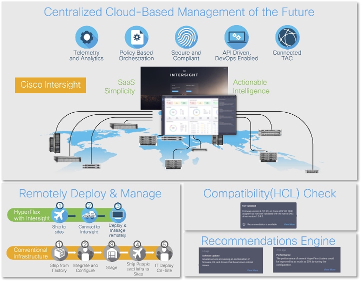
Cisco Intersight is a lifecycle management platform for your infrastructure, regardless of location. In your enterprise data center, at the edge, in remote and branch offices, at retail and industrial sites—all these locations present unique management challenges and typically require separate tools. Cisco Intersight Software as a Service (SaaS) unifies and simplifies your experience of the Cisco Unified Computing System and Cisco HyperFlex systems. See Figure 1.
Cisco Compute Hyperconverged HCIAF240C M7 All-NVMe/All-Flash Servers
The Cisco Compute Hyperconverged HCIAF240C M7 All-NVMe/All-Flash Servers extends the capabilities of Cisco’s Compute Hyperconverged portfolio in a 2U form factor with the addition of the 4th Gen Intel® Xeon® Scalable Processors (codenamed Sapphire Rapids), 16 DIMM slots per CPU for DDR5-4800 DIMMs with DIMM capacity points up to 256GB.
The All-NVMe/all-Flash Server supports 2x 4th Gen Intel® Xeon® Scalable Processors (codenamed Sapphire Rapids) with up to 60 cores per processor. It has memory up to 8TB with 32 x 256GB DDR5-4800 DIMMs in a 2-socket configuration. There are two servers to choose from:
● HCIAF240C-M7SN with up to 24 front facing SFF NVMe SSDs (drives are direct-attach to PCIe Gen4 x2)
● HCIAF240C-M7SX with up to 24 front facing SFF SAS/SATA SSDs
For more details, go to: HCIAF240C M7 All-NVMe/All-Flash Server specification sheet.

This chapter contains the following:
Table 1 lists the required physical components and hardware.
Table 1. Cisco Compute Hyperconverged (CCHC) with Nutanix in Intersight standalone mode (ISM) Components
| Component |
Hardware |
| Network Switches |
Two (2) Cisco UCS 6454 Nexus switches |
| Servers |
Four (4) Cisco C240 M7 All NVMe servers |
Table 2 lists the software components and the versions required for a single cluster of the Citrix Virtual Apps and Desktops (CVAD) Virtual Desktop Infrastructure (VDI) on Cisco Compute Hyperconverged with Nutanix in Intersight Standalone Mode (ISM), as tested, and validated in this document.
Table 2. Software Components and Hardware
| Component |
Hardware |
| Foundation Central |
1.6 |
| pc.2024.1.0.1 |
|
| AOS and AHV bundled |
nutanix_installer_package-release-fraser-6.8.0.1 |
| Nutanix VirtIO |
1.2.3 |
| Cisco UCS Firmware |
Cisco UCS C-Series bundles, revision 4.3(3.240043) |
| Nutanix AHV Citrix Plug-in |
2.7.7 |
| Citrix Virtual Apps and Desktops |
2203 LTSR |
| Citrix Provisioning Services |
2203 LTSR |
Cisco Compute Hyperconverged (CCHC) with Nutanix cluster built using Cisco HCIAF240C M7 Series rack-mount servers. The two Cisco Nexus switches connect to every Cisco Compute Hyperconverged server. Upstream network connections, referred to as “northbound” network connections are made from the Nexus switches to the customer datacenter network at the time of installation.
The Day0 deployment is managed through Cisco Intersight and Nutanix Foundation Central and is enabled through Prism Central.

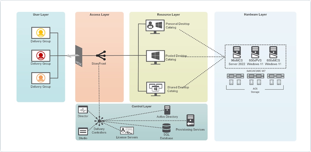
Figure 4 illustrates the logical architecture of the validated solution, which is designed to run desktop and RDS server VMs supporting up to 600 users on a single Cisco Compute Hyperconverged (CCHC) 4-node cluster with Nutanix, with physical redundancy for the rack servers and a separate cluster to host core services and management components.
Note: Separating management components and desktops is a best practice for the large environments.
Design Considerations for Desktop Virtualization
There are many reasons to consider a virtual desktop solution, such as an ever-growing and diverse base of user devices, complexity in managing of traditional desktops, security, and even Bring Your Own Device (BYOD) to work programs. The first step in designing a virtual desktop solution is understanding the user community and the tasks required to execute their role successfully. The Citrix VDI Handbook offers detailed information on user classification and the types of virtual desktops.
The following user classifications by the workload impact overall density and the VDI model:
● Knowledge Workers - 2-10 office productivity apps with light multimedia use.
● Task Workers - 1-2 office productivity apps or kiosks.
● Power Users – Advanced applications, data processing, or application development.
● Graphic-Intensive Users – High-end graphics capabilities, 3D rendering, CAD, and other GPU-intensive tasks.
After the user classifications have been identified and the business requirements for each user classification have been defined, it becomes essential to evaluate the types of virtual desktops that are needed based on user requirements. Below is the Citrix set of VDI models for each user:
● Hosted Apps: Delivers application interfaces to users, simplifying the management of key applications.
● Shared Desktop: Hosts multiple users on a single server-based OS, offering a cost-effective solution, but users have limited system control.
● Pooled Desktop: Provides temporary desktop OS instances to users, reducing the need for multi-user compatible applications.
● Persistent Desktop: Offers a customizable, dedicated desktop OS for each user, ideal for those needing persistent settings.
● GPU Desktop: Provides dedicated GPU resources for enhanced graphical performance.
● vGPU: Allows multiple VMs to share a single physical GPU for better graphics processing.
● Remote PC Access: Secure remote access to a user’s physical office PC.
● Web and SaaS Application Access: Offers secure, flexible access to web/SaaS apps with enhanced security and governance.
Understanding Applications and Data
When the desktop user groups and sub-groups have been identified, the next task is to catalog group application and data requirements. This can be one of the most time-consuming processes in the VDI planning exercise, but it is essential for the VDI project’s success. Performance will be negatively affected if the applications and data are not identified and co-located.
The inclusion of cloud applications, such as SalesForce.com, will likely complicate the process of analyzing an organization's variety of applications and data pairs. This application and data analysis is beyond the scope of this Cisco Validated Design but should not be omitted from the planning process. Various third-party tools are available to assist organizations with this crucial exercise.
Sizing
The following key project and solution sizing questions should be considered:
● Has a VDI pilot plan been created based on the business analysis of the desktop groups, applications, and data?
● Is there infrastructure and budget in place to run the pilot program?
● Are the required skill sets to execute the VDI project available? Can we hire or contract for them?
● Do we have end-user experience performance metrics identified for each desktop sub-group?
● How will we measure success or failure?
● What is the future implication of success or failure?
Below is a short, non-exhaustive list of sizing questions that should be addressed for each user sub-group:
● What is the Single-session OS version?
● How many virtual desktops will be deployed in the pilot? In production?
● How much memory per target desktop group desktop?
● Are there any rich media, Flash, or graphics-intensive workloads?
● Are there any applications installed? What application delivery methods will be used, Installed, Streamed, Layered, Hosted, or Local?
● What is the Multi-session OS version?
● What is the virtual desktop deployment method?
● What is the hypervisor for the solution?
● What is the storage configuration in the existing environment?
● Are there sufficient IOPS available for the write-intensive VDI workload?
● Will there be storage dedicated and tuned for VDI service?
● Is there a voice component to the desktop?
● Is there a 3rd party graphics component?
● Is anti-virus a part of the image?
● Is user profile management (for example, non-roaming profile-based) part of the solution?
● What are the fault tolerance, failover, and disaster recovery plans?
● Are there additional desktop sub-group-specific questions?
Install and Configure Nutanix cluster on Cisco Compute Hyperconverged Servers in Standalone Mode
This chapter contains the following:
● Install Nutanix on Cisco Compute Hyperconverged Servers in Intersight Standalone Mode
● Configure Cisco Nexus Switches
This chapter provides an introduction to the solution deployment for Nutanix on Cisco Compute Hyperconverged Servers in Intersight Standalone Mode (ISM). The Intersight Standalone Mode requires the Cisco Compute Hyperconverged Servers to be directly connected to an ethernet switches and the servers are claimed through Cisco Intersight.
For the complete step-by-step procedures for implementing and managing the deployment of the Nutanix cluster in the ISM mode, refer to the Cisco Deployment guide: Cisco Compute Hyperconverged with Nutanix in Intersight Standalone Mode Design and Deployment Guide.
Before beginning the installation of Nutanix Cluster on Cisco Compute Hyperconverged servers in Intersight Standalone Mode, you should ensure they have deployed Nutanix Prism Central and enabled Nutanix Foundation Central through the Nutanix marketplace available through Prism Central. Foundation Central can create clusters from factory-imaged nodes and reimage existing nodes registered with Foundation Central from Prism Central. This provides benefits such as creating and deploying several clusters on remote sites, such as ROBO, without requiring onsite visits
At a high level, to continue with the deployment of Nutanix on Cisco Compute Hyperconverged servers in Intersight standalone mode (ISM), ensure the following:
● Prism Central is deployed on a Nutanix Cluster
● Foundation Central 1.6 or later is enabled on Prism Central
● A local webserver is available hosting Nutanix AOS image
Note: Prism Central 2022.9 or later to support Windows 11 on AHV.
Note: In this solution, using the Cisco Intersight Advantage License Tier enables the following:
Configuration of Server Profiles for Nutanix on Cisco Compute Hyperconverged Rack Servers
Integration of Cisco Intersight with Foundation Central for Day 0 to Day N operations.
Install Nutanix on Cisco Compute Hyperconverged Servers in Intersight Standalone Mode
Figure 5 shows the high-level configuration of Cisco Compute Hyperconverged Servers in Intersight Standalone Mode (ISM) for Nutanix.
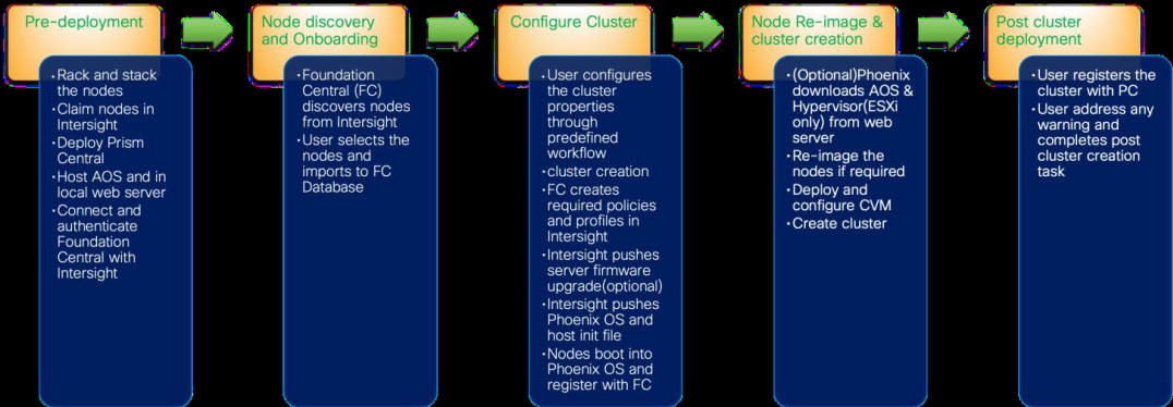
The following sections detail the physical connectivity configuration of the Nutanix cluster on Cisco Compute Hyperconverged servers in standalone mode.
Note: This document is intended to allow the reader to configure the Citrix Virtual Apps and Desktops customer environment as a stand-alone solution
This section provides information on cabling the physical equipment in this Cisco Validated Design environment.
Note: This document assumes that out-of-band management ports are plugged into an existing management infrastructure at the deployment site. These interfaces will be used in various configuration steps.
Note: Follow the cabling directions in this section. Failure to do so will cause problems with your deployment.
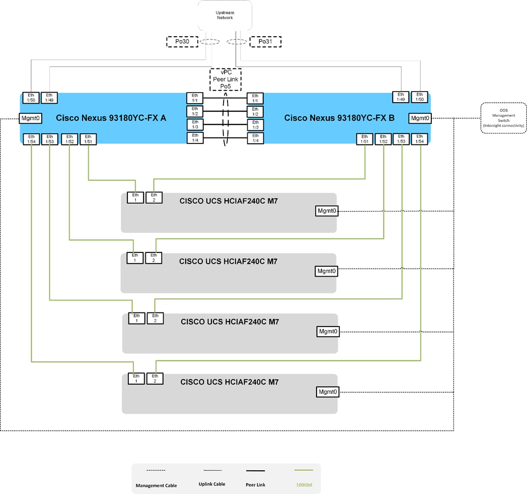
Figure 6 details the cable connections used in the validation lab for Cisco Compute Hyperconverged with Nutanix ISM topology based on the Cisco Nexus 9000 Series data center switches. 100Gb links connect the Cisco Compute Hyperconverged servers to the Cisco Nexus Switches. Additional 1Gb management connections will be needed for an out-of-band network switch that sits apart from the CCHC infrastructure. Each Cisco Nexus switch is connected to the out-of-band network switch. Layer 3 network connectivity is required between the Out-of-Band (OOB) and In-Band (IB) Management Subnets.
Configure Cisco Nexus Switches
Before beginning the installation, configure the following ports, settings, and policies in the Cisco Nexus 93180YC-FX interfaces.
The solution described in this document provides details for configuring a fully redundant configuration. Configuration guidelines refer to which redundant component is configured with each step, whether A or B. For example, Cisco Nexus A and Cisco Nexus B identify the pair of configured Cisco Nexus switches.
The VLAN configuration recommended for the environment includes six VLANs as listed in Table 3. The ports were configured in the trunk mode to support multiple VLANs presented to the servers,
Note: MTU 9216 is not required but recommended in case jumbo frames are ever used in the future
| VLAN Name |
VLAN ID |
VLAN Purpose |
Subnet Name |
VLAN ID |
| Default |
1 |
Native VLAN |
Default |
1 |
| InBand-Mgmt_70 |
70 |
In-Band management interfaces |
VLAN-70 |
70 |
| Infra-Mgmt_71 |
71 |
Infrastructure Virtual Machines |
VLAN-71 |
71 |
| VDI_72 |
72 |
RDSH, VDI Persistent and Non-Persistent 1 |
VLAN-72 |
72 |
| OOB |
132 |
Out-Of-Band connectivity |
VLAN-132 |
|
1VDA workloads were deployed and tested individually, one at a time.
| Tech tip |
| It is recommended to use VLAN segmentation to accommodate various VDA workloads in a hybrid deployment. |
Procedure 1. Configure Cisco Nexus A
Step 1. Log in as “admin” user into the Cisco Nexus Switch A.
Step 2. Use the device CLI to configure the hostname to make it easy to identify the device, enable services used in your environment and disable unused services.
Step 3. Configure the local login and password:
interface Ethernet1/51
description C240M7 Nutanix A
switchport mode trunk
switchport trunk allowed vlan 1-132
spanning-tree port type edge trunk
mtu 9216
no shutdown
interface Ethernet1/52
description C240M7 Nutanix A
switchport mode trunk
switchport trunk allowed vlan 1-132
spanning-tree port type edge trunk
mtu 9216
no shutdown
interface Ethernet1/53
description C240M7 Nutanix A
switchport mode trunk
switchport trunk allowed vlan 1-132
spanning-tree port type edge trunk
mtu 9216
no shutdown
interface Ethernet1/54
description C240M7 Nutanix A
switchport mode trunk
switchport trunk allowed vlan 1-132
spanning-tree port type edge trunk
mtu 9216
no shutdown
copy running-config startup-config
Procedure 2. Configure Cisco Nexus B
Step 1. Log in as “admin” user into the Cisco Nexus Switch B.
Step 2. Use the device CLI to configure the hostname to make it easy to identify the device, enable services used in your environment and disable unused services.
Step 3. Configure the local login and password:
interface Ethernet1/51
description C240M7 Nutanix B
switchport mode trunk
switchport trunk allowed vlan 1-132
spanning-tree port type edge trunk
mtu 9216
no shutdown
interface Ethernet1/52
description C240M7 Nutanix B
switchport mode trunk
switchport trunk allowed vlan 1-132
spanning-tree port type edge trunk
mtu 9216
no shutdown
interface Ethernet1/53
description C240M7 Nutanix B
switchport mode trunk
switchport trunk allowed vlan 1-132
spanning-tree port type edge trunk
mtu 9216
no shutdown
interface Ethernet1/54
description C240M7 Nutanix B
switchport mode trunk
switchport trunk allowed vlan 1-132
spanning-tree port type edge trunk
mtu 9216
no shutdown
copy running-config startup-config
This procedure describes the post-cluster creation steps.
Procedure 1. Create a VM network subnet
Step 1. Log into the Cluster VIP with admin - Nutanix/4u and change the password.
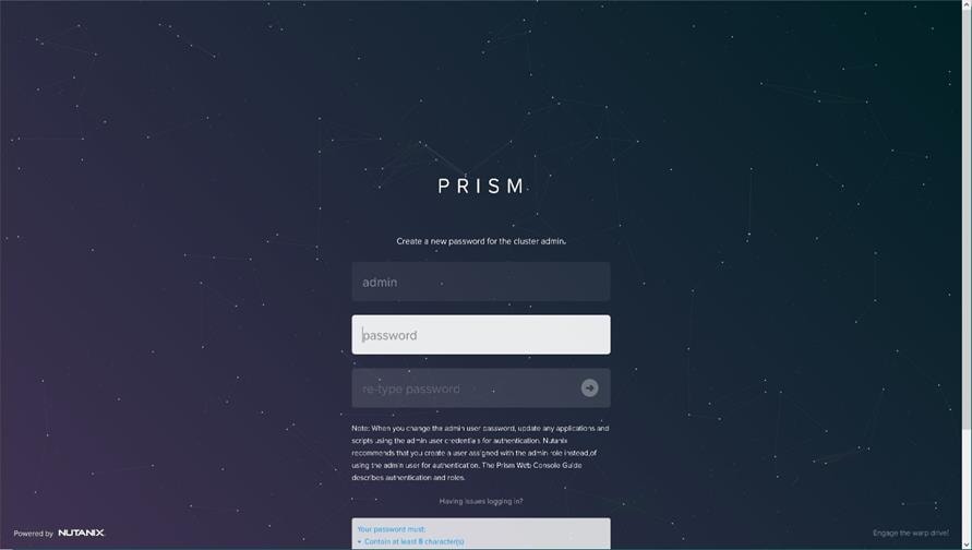
Step 2. Go to Cluster details, enter the iSCSI data services IP, and enable Retain Deleted VMs for 1 day. Click Save.
Configure Subnets
To create additional subnets used by virtual desktops follow the steps below. The subnets from the Table 4 were created for this validated design.
Procedure 1. Create a VM network subnet
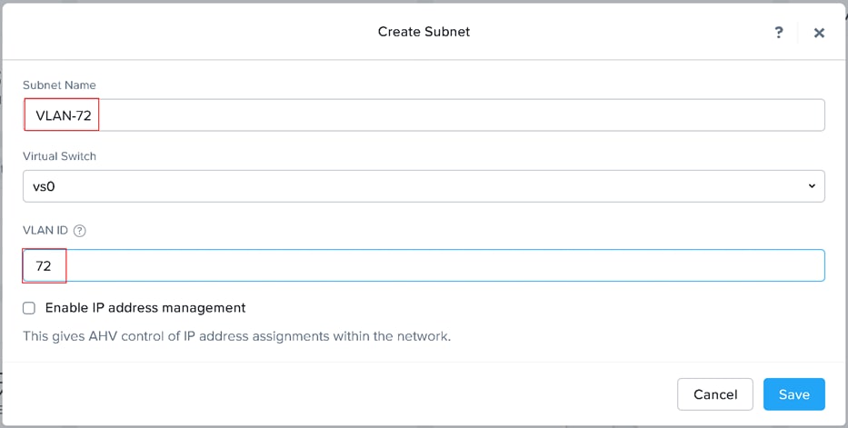
Step 1. Go to the VM tab and click Network Config link.

Step 2. Click +Create Subnet.

Step 3. Enter Subnet Name and VLAN ID for your subnet. Click Save. Repeat for any additional VLANs you are introducing to virtual desktops.
Configure Storage Container
To create a Storage Container to host virtual desktops, follow the steps below. A single container was created for single-session and multi-session desktops.
Procedure 1. Create Storage container for virtual desktops
Step 1. Go to the Storage tab and click + Storage Container.

Step 2. Enter container name, select Compression, and then click Save.

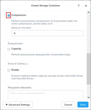
| Nutanix recommends enabling compression for Virtual Apps or Virtual Desktops as a general best practice; only enable the Elastic Deduplication Engine for full clones. Erasure coding isn't a suitable data reduction technology for desktop virtualization. Note: Full clones in the table above are persistent machines including MCS full clone persistent machines. Citrix MCS are nonpersistent machines. |
Install and Configure Citrix Virtual Apps and Desktops
This chapter contains the following:
● Build the Virtual Machines and Environment for Workload Testing
● Install Citrix Virtual Apps and Desktops Delivery Controller, Citrix Licensing, and StoreFront
● Install and Configure Citrix Provisioning Server
Citrix recommends using Secure HTTP (HTTPS) and a digital certificate to protect communications. Citrix recommends using a digital certificate issued by a certificate authority (CA) according to your organization's security policy. In our testing, the implementation of CA was not carried out.
Build the Virtual Machines and Environment for Workload Testing
Create the necessary DHCP scopes for the environment and set the Scope Options.

Software Infrastructure Configuration
This section explains how to configure this solution's software infrastructure components.
Install and configure the infrastructure virtual machines by following the process listed in Table 4.
Table 4. Test Infrastructure Virtual Machine Configuration
| Configuration |
Microsoft Active Directory DCs Virtual Machine |
Citrix Virtual Apps and Desktops Controllers Virtual Machines |
| Operating system |
Microsoft Windows Server 2019 |
Microsoft Windows Server 2022 |
| Virtual CPU amount |
4 |
6 |
| Memory amount |
8 GB |
24 GB |
| Network |
Infra-Mgmt_71 |
Infra-Mgmt-71 |
| Disk-1 (OS) size |
40 GB |
96 GB |
| Disk-2 size |
|
|
| Configuration |
Microsoft SQL Server Virtual Machine |
Citrix Provisioning Servers Virtual Machines |
| Operating system |
Microsoft Windows Server 2019 |
Microsoft Windows Server 2022 |
| Virtual CPU amount |
6 |
6 |
| Memory amount |
24GB |
96 GB |
| Network |
Infra-Mgmt_71 |
VLAN_72 |
| Disk-1 (OS) size |
40 GB |
40 GB |
| Disk-2 size |
100 GB SQL Databases\Logs |
200 GB Disk Store |
| Configuration |
Citrix StoreFront Controller Virtual Machine |
| Operating system |
Microsoft Windows Server 2022 |
| Virtual CPU amount |
4 |
| Memory amount |
8 GB |
| Network |
Infra-Mgmt-71 |
| Disk-1 (OS) size |
96 GB |
| Disk-2 size |
|
Create the Golden Images
This section guides creating the golden images for the environment.
Major steps involved in preparing the golden images: installing and optimizing the operating system, installing the application software, and installing the Virtual Delivery Agents (VDAs).
Note: For this CVD, the images contain the basics needed to run the Login VSI workload.
The single-session OS and multi-session OS master target virtual machines were configured as detailed in Table 5.
Table 5. Single-session OS and Multi-session OS Virtual Machines Configurations
| Configuration |
Single-session OS Virtual Machine |
Mutli-session OS Virtual Machine |
| Operating system |
Microsoft Windows 11 64-bit 21H2 (19044.2006) |
Microsoft Windows Server 2022 21H2 (20348.2227) |
| Virtual CPU amount |
2 |
4 |
| Memory amount |
4 GB |
24 GB |
| Network |
VDI_72 |
VDI_72 |
| vDisk size |
64 GB |
96 GB |
| Additional software used for testing |
Microsoft Office 2021 Office Update applied |
Microsoft Office 2021 Office Update applied |
| Additional Configuration |
Configure DHCP Add to domain Activate Office CVAD Agent Install FSLogix 2210 hotfix 1 |
Configure DHCP Add to domain Activate Office CVAD Agent Install FSLogix 2210 hotfix 1 |
Procedure 1. Install Windows 11 Operating System
Using the following procedure, you can create a virtual machine with the vTPM configuration enabled.
Note: To create a virtual machine with vTPM enabled using Prism Central, the version PC.2022.9 or later is required. The Prism Central PC.2024.1.0.1 was deployed on the cluster. For additional details, refer to the Nutanix Tech note: Windows 11 on Nutanix AHV.
Step 1. Log in to Prism Central as an administrator.
Step 2. Select Infrastructure in the Application Switcher.
Step 3. Go to Compute & Storage > VMs and click Create VM.
Step 4. The Create VM wizard appears. Continue with wizard making appropriate selections for vCPU(s), Memory, Disks, Networks.
Note: Create two CD-ROMs to support VirtIO installation alongside Windows 11 OS.
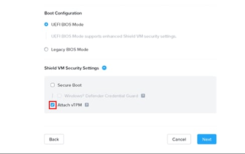
Step 5. At the Shield VM Security Settings, click the Attach vTPM checkbox.
Step 6. Click Next at the subsequent VM setting tabs and then click Save
Step 7. Mount ISOs with VirtIO drivers and Windows 11 to CDROMs.
Step 8. Power on VM and follow the installation wizard.
Step 9. Provide VirtIO drivers from CDROM.
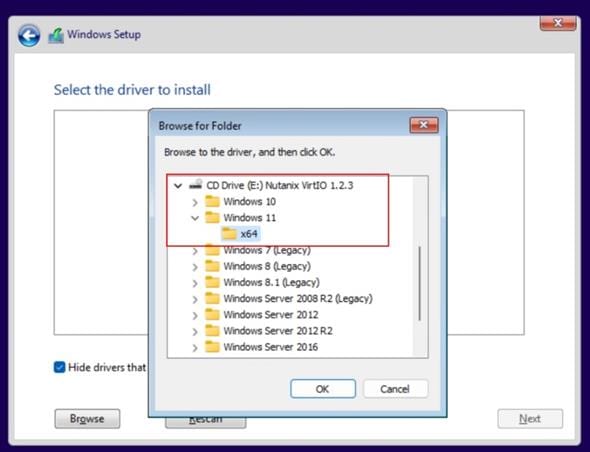
Step 10. Select drivers to be installed and click Next.
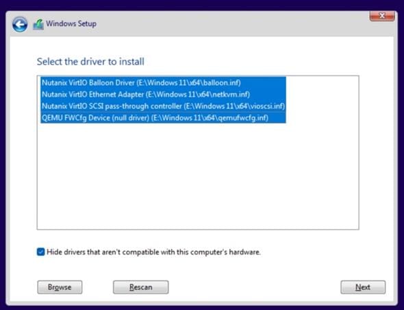
Step 11. Continue with OS installation until completed
Step 12. Remove the second CD-ROM after installation.
Procedure 2. Install Windows Server 2022 Operating System
Step 1. Log in to Prism Central as an administrator.
Step 2. Select Infrastructure in the Application Switcher.
Step 3. Go to Compute & Storage > VMs and click Create VM.
Step 4. The Create VM wizard appears. Continue with wizard making appropriate selections for vCPU(s), Memory, Disks, Networks.
Note: Create two CD-ROMs to support VirtIO installation alongside Windows Server 2022 OS.
Step 5. Click Next at the subsequent VM setting tabs and then click Save
Step 6. Mount ISOs with VirtIO drivers and Windows Server 2022 to CDROMs.
Step 7. Power on VM and follow the installation wizard.
Step 8. Provide VirtIO drivers from CDROM.
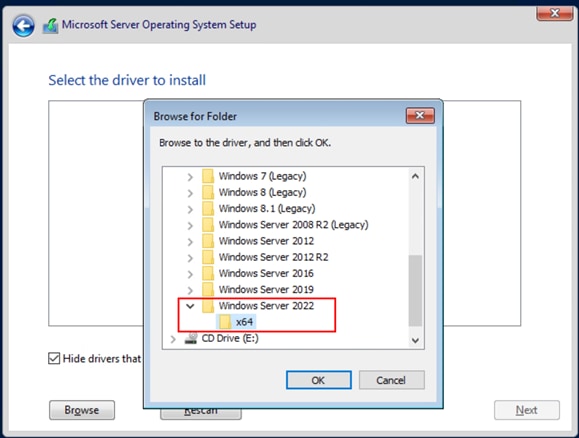
Step 9. Select drivers to be installed and click Next.
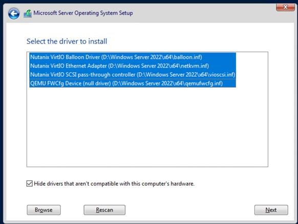
Step 10. Continue with OS installation until completed
Step 11. Remove the second CD-ROM after installation.
After OS installation is completed, install Microsoft Office and apply security updates.
The final step is to optimize the Windows OS. The Citrix Optimizer Tool includes customizable templates to enable or disable Windows system services and features using Citrix recommendations and best practices across multiple systems. Since most Windows system services are enabled by default, the optimization tool can easily disable unnecessary services and features to improve performance.
Note: In this CVD, the Citrix Optimizer Tool - v3.1.0.3 was used. Base images were optimized with the Default template for Windows 11 version 21H2, 22H2 (2009), or Windows Server 2022 version 21H2 (2009) from Citrix. Additionally, Windows Defender was disabled on the Windows 11 PVS golden image.
Install Virtual Delivery Agents (VDAs)
Virtual Delivery Agents (VDAs) are installed on the server and workstation operating systems, enabling connections for desktops and apps. This procedure was used to install VDAs for both Single-session and Multi-session OS.
Procedure 1. Install Citrix Virtual Apps and Desktops Virtual Desktop Agents
Virtual Delivery Agents (VDAs) are installed on the server and workstation operating systems, enabling connections for desktops and apps. This procedure was used to install VDAs for both Single-session and Multi-session OS.
When you install the Virtual Delivery Agent, Citrix User Profile Management is silently installed on master images by default.
Note: Using profile management as a profile solution is optional but Microsoft FSLogix was used for this CVD and is described later.
Step 1. Launch the Citrix Virtual Apps and Desktops installer from the Citrix_Virtual_Apps_and_Desktops_7_2203_4000 ISO.
Step 2. Click Start in the Welcome Screen.
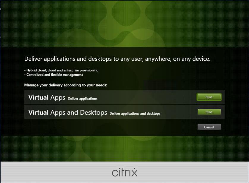
Step 3. To install the VDA for the Hosted Virtual Desktops (VDI), select Virtual Delivery Agent for Windows Single-session OS.
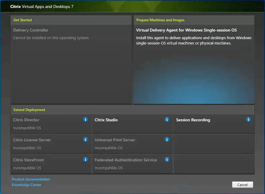
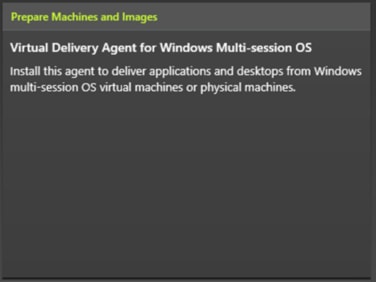
Note: Select Virtual Delivery Agent for Windows Multi-session OS when building an image for Microsoft Windows Server 2022.
Step 4. Select Create a master MCS Image.
Step 5. Click Next.
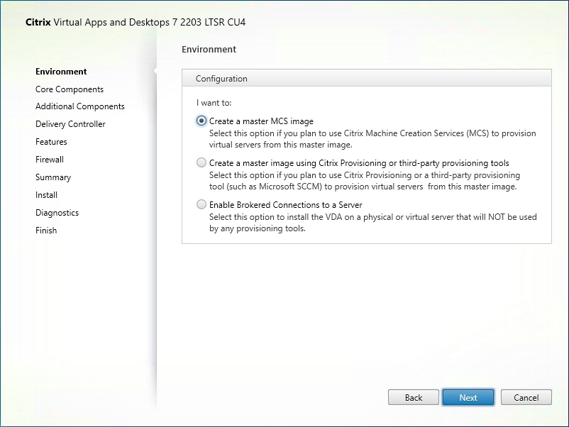
Note: Select Create a master image using Citrix Provisioning or third-party provisioning tools when building an image to be delivered with Citrix Provisioning tools.

Step 6. Optional: do not select Citrix Workspace App.
Step 7. Click Next.
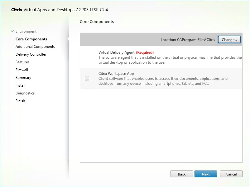
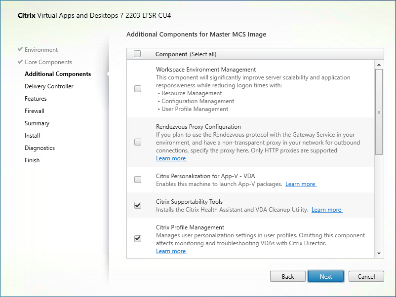
Step 8. Select the additional components required for your image. In this design, only default components were installed on the image.
Step 9. Click Next.
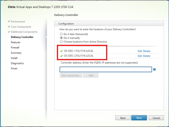
Step 10. Configure Delivery Controllers at this time by letting MCS do it automatically.
Step 11. Click Next.
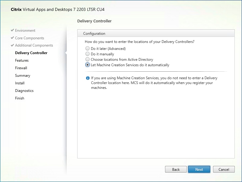
Note: Manually configure Delivery Controllers at this time when building an image to be delivered with Citrix Provisioning tools.
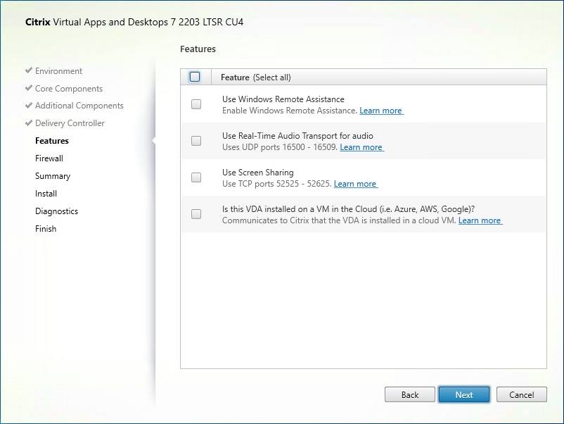
Step 12. Optional: select additional features.
Step 13. Click Next.
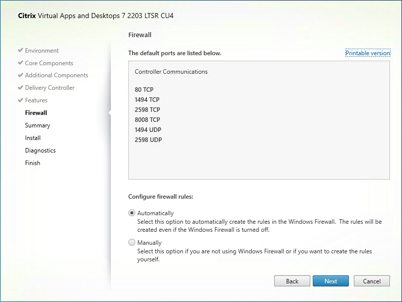
Step 14. Select the firewall rules to be configured Automatically.
Step 15. Click Next.
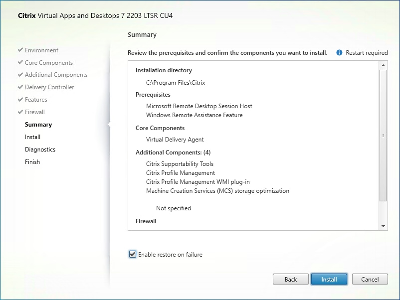
Step 16. Verify the Summary and click Install.
Step 17. Optional: configure Citrix Call Home participation.
Step 18. Click Next.
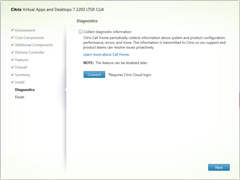
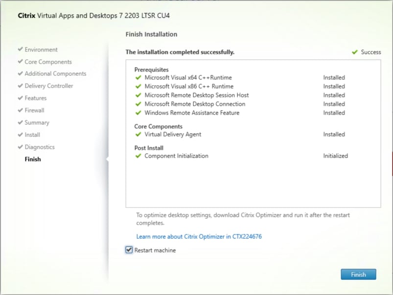
Step 19. Select Restart Machine.
Step 20. Click Finish and the machine will reboot automatically.
Procedure 2. Install the Citrix Provisioning Server Target Device Software
The Master Target Device refers to the target device from which a hard disk image is built and stored on a vDisk. Provisioning Services then streams the contents of the vDisk created to other target devices. This procedure installs the PVS Target Device software used to build the VDI golden images.
Step 1. Launch the PVS installer from the Citrix_Provisioning_2203_CU4 ISO.
Step 2. Click Target Device Installation.
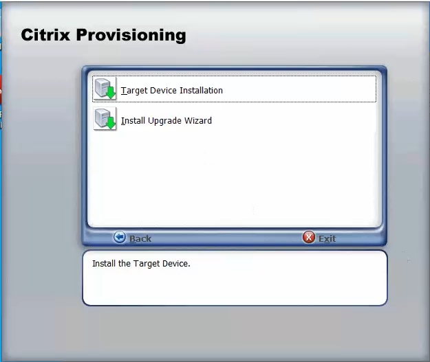
The installation wizard will check to resolve dependencies and then begin the PVS target device installation process.
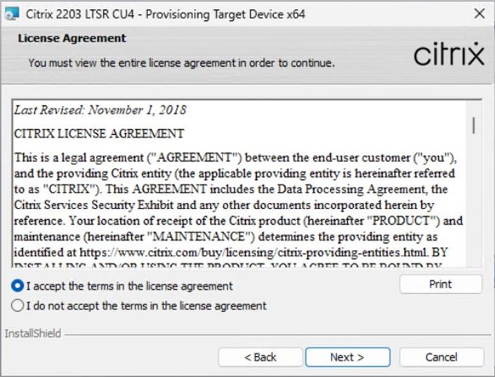
Step 3. Click Next.
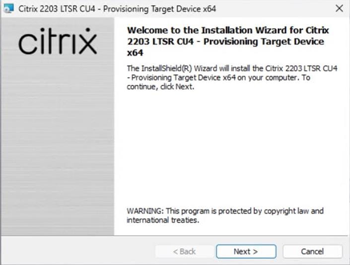
Step 4. Indicate your acceptance of the license by selecting the I have read, understand, and accept the terms of the license agreement.
Step 5. Click Next.
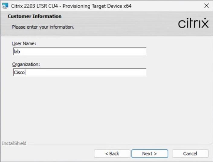
Step 6. Optionally: provide the Customer information.
Step 7. Click Next.
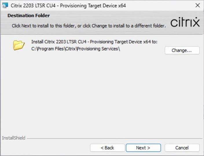
Step 8. Accept the default installation path.
Step 9. Click Next.
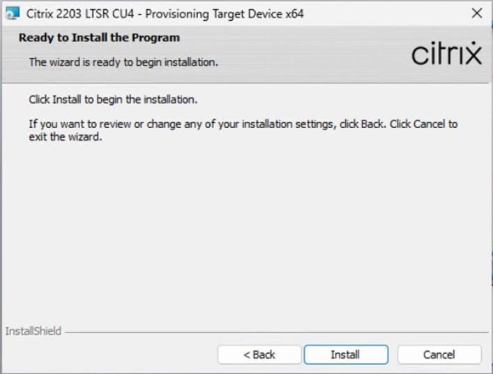
Step 10. Click Install.
Step 11. Deselect the checkbox to launch the Imaging Wizard and click Finish.
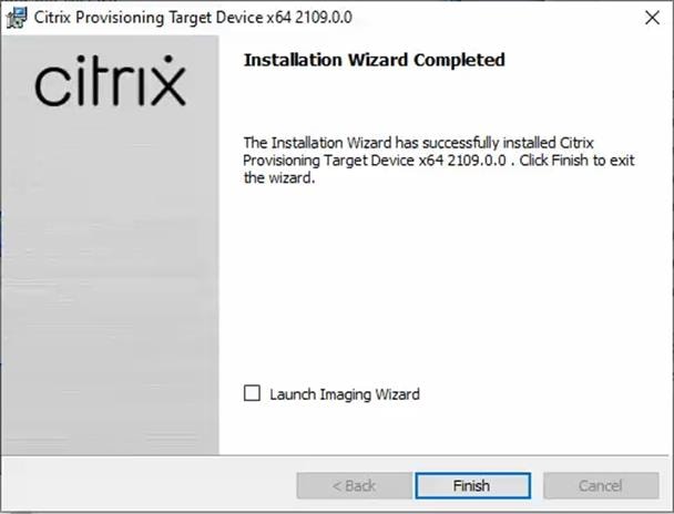
Step 12. Click Yes to reboot the machine.
Procedure 3. Create Citrix Provisioning Server vDisks
The Citrix Provisioning Server must be installed and configured before a base vDisk can be created. The PVS Imaging Wizard automatically creates the base vDisk image from the master target device.
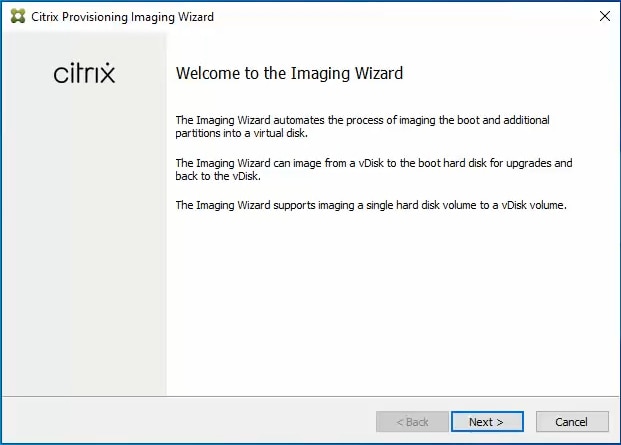
Step 1. Log in to PVS target virtual machine and start PVS Imaging Wizard.
Step 2. PVS Imaging Wizard's Welcome page appears. Click Next.
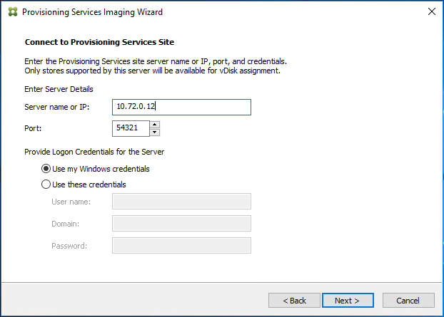
Step 3. The Connect to Farm page appears. Enter the name or IP address of a Provisioning Server within the farm to connect to and the port to use to make that connection.
Step 4. Use the Windows credentials (default) or enter different credentials.
Step 5. Click Next.
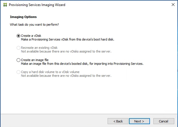
Step 6. Select Create a vDisk.
Step 7. Click Next.
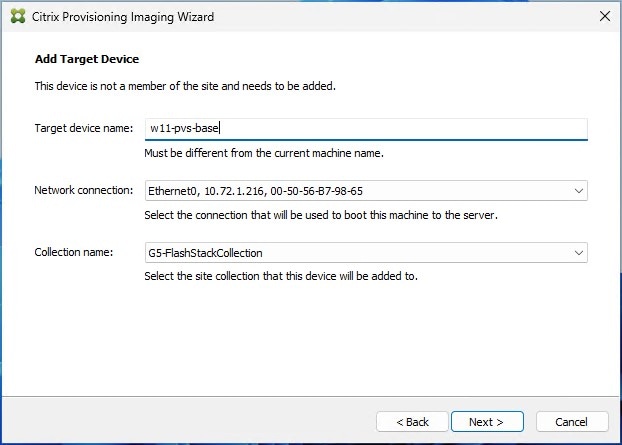
The Add Target Device page appears.
Step 8. Select the Target Device Name, the MAC address associated with one of the NICs that was selected when the target device software was installed on the master target device, and the Collection to which you are adding the device.
Step 9. Click Next.
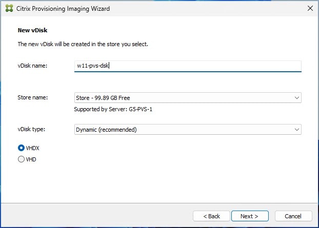
Step 10. The New vDisk dialog displays. Enter the name of the vDisk.
Step 11. Select the Store where the vDisk will reside. Select the vDisk type, either Fixed or Dynamic, from the drop-down list.
Note: This CVD used Dynamic rather than Fixed vDisks.
Step 12. Click Next.
Step 13. In the Microsoft Volume Licensing page, select the volume license option to use for target devices. For this CVD, volume licensing is not used, so the None button is selected.
Step 14. Click Next.

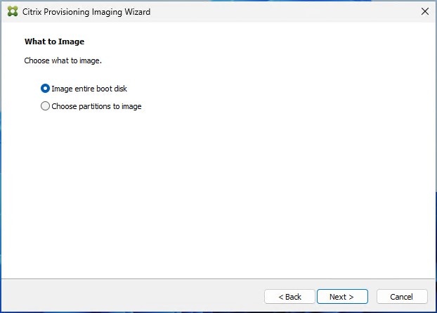
Step 15. Select Image entire boot disk on the Configure Image Volumes page.
Step 16. Click Next.
Step 17. Select Optimize for hard disk again for Provisioning Services before imaging on the Optimize Hard Disk for Provisioning Services.
Step 18. Click Next.

Step 19. Click Create on the Summary page.
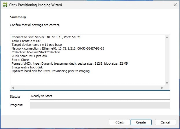
Step 20. Review the configuration and click Continue.
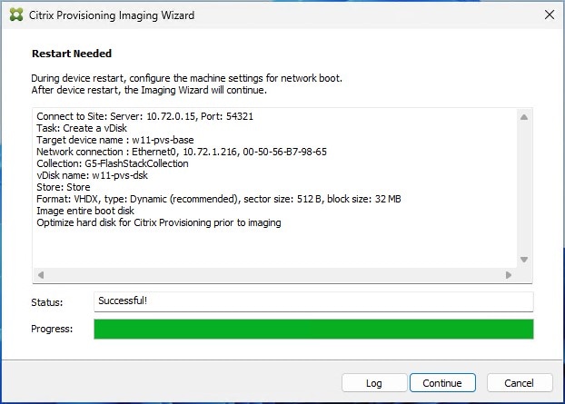
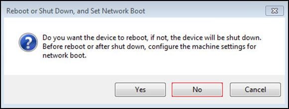
Step 21. When prompted, click No to shut down the machine.
Step 22. To enable a VM to boot over the network using Acropolis CLI (aCLI). Log in as nutanix user to any CVM in the cluster using SSH.
Step 23. Obtain the MAC address of the virtual interface of PVS master virtual machine:
nutanix@cvm$ acli vm.nic_list pvs-master-vm
Step 24. Update the boot device setting so that the VM boots over the network:
nutanix@cvm$ acli vm.update_boot_device pvs-master-vm mac_addr=mac_addr
Step 25. After restarting the virtual machine, log in to the master target. The PVS imaging process begins, copying the contents of the C: drive to the PVS vDisk located on the server.
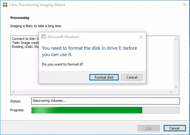
Step 26. If prompted to format the disk, disregard the message, and allow the Provisioning Imaging Wizard to finish.
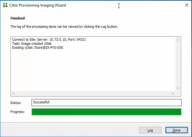
Step 27. A message is displayed when the conversion is complete, click Done.
Step 28. Shutdown the virtual machine used as the master target.
Step 29. Connect to the PVS server and validate that the vDisk image is available in the Store.
Step 30. Right-click the newly created vDisk and select Properties.
Step 31. On the vDisk Properties dialog, Microsoft Volume Licensing tab select the appropriate mode for your deployment.
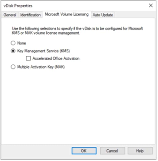
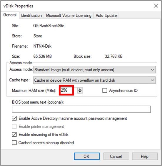
Step 32. On the vDisk Properties dialog, change Access mode to Standard Image (multi-device, read-only access).
Step 33. Set the Cache Type to Cache in device RAM with overflow on hard disk.
Step 34. Set Maximum RAM size (MBs): 256.
Step 35. Click OK.
| Tech tip |
| Citrix recommends at least 256 MB of RAM for a Desktop OS and 1 GB for Server OS if RAM cache is being used. Nutanix prefers not to use the RAM cache. Set this value to 0, and only the local hard disk will be used to cache. |
Install and Configure FSLogix
In this CVD, FSLogix, a Microsoft tool, was used to manage user profiles.
A Windows user profile is a collection of folders, files, registry settings, and configuration settings that define the environment for a user who logs on with a particular user account. Depending on the administrative configuration, the user may customize these settings. Profile management in VDI environments is an integral part of the user experience.
FSLogix allows you to:
● Roam user data between remote computing session hosts
● Minimize sign-in times for virtual desktop environments
● Optimize file IO between host/client and remote profile store
● Provide a local profile experience, eliminating the need for roaming profiles
● Simplify the management of applications and 'Gold Images'
Additional documentation about the tool can be found here.
Procedure 1. FSLogix Apps Installation
Step 1. Download the FSLogix file here.
Step 2. Run FSLogixAppSetup.exe on the VDI master image (32-bit or 64-bit depending on your environment).
Step 3. Click OK to proceed with the default installation folder.
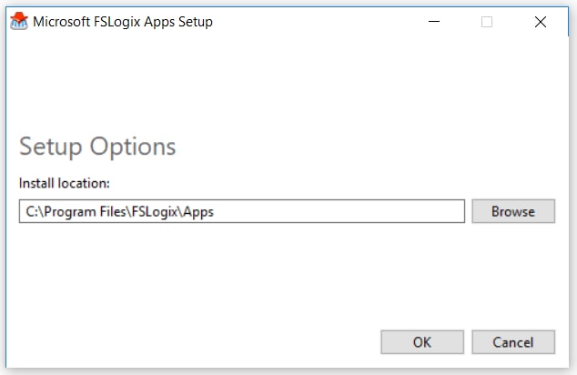
Step 4. Review and accept the license agreement.
Step 5. Click Install.
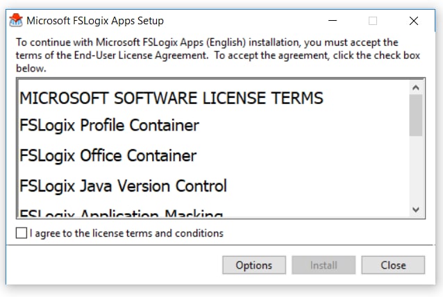
Step 6. Reboot.
Procedure 2. Configure Profile Container Group Policy
Step 1. Copy fslogix.admx to C:\Windows\PolicyDefinitions, and fslogix.adml to C:\Windows\PolicyDefinitions\en-US on Active Directory Domain Controllers.
Step 2. Create FSLogix GPO and apply to the desktops OU:
● Go to Computer Configuration > Administrative Templates > FSLogix > Profile Containers.
● Configure the following settings:
◦ Enabled – Enabled
◦ VHD location – Enabled, with the path set to \\<FileServer>\<Profiles Directory>
Note: Consider enabling and configuring FSLogix logging, limiting the size of the profiles, and excluding additional directories.
Install Citrix Virtual Apps and Desktops Delivery Controller, Citrix Licensing, and StoreFront
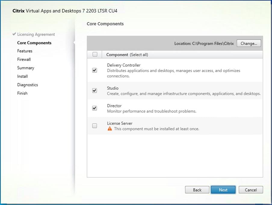
The process of installing the Citrix Virtual Apps and Desktops Delivery Controller also installs other key Citrix Virtual Apps and Desktops software components, including Studio, which creates and manages infrastructure components, and Director, which monitors performance and troubleshoots problems.
Note: Dedicated StoreFront and License servers should be implemented for large-scale deployments.
Procedure 1. Install Citrix License Server
Step 1. To begin the installation, connect to the first Citrix License server and launch the installer from the Citrix_Virtual_Apps_and_Desktops_7_2203_4000 ISO.
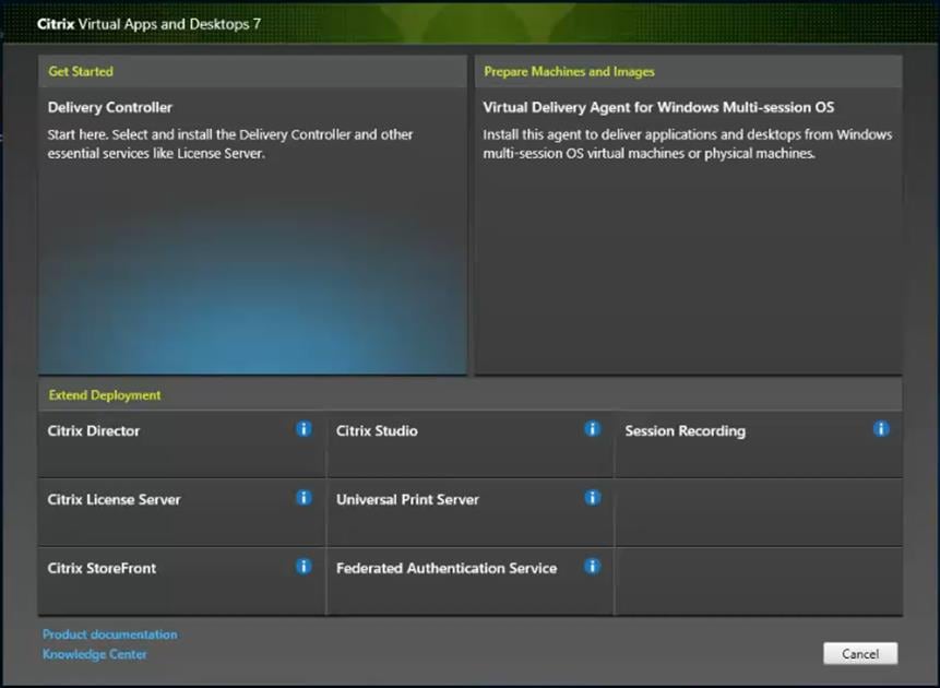
Step 2. Click Start.

Step 3. Click Extend Deployment – Citrix License Server.
Step 4. Read the Citrix License Agreement. If acceptable, indicate your acceptance of the license by selecting I have read, understand, and accept the terms of the license agreement.
Step 5. Click Next.

Step 6. Click Next.
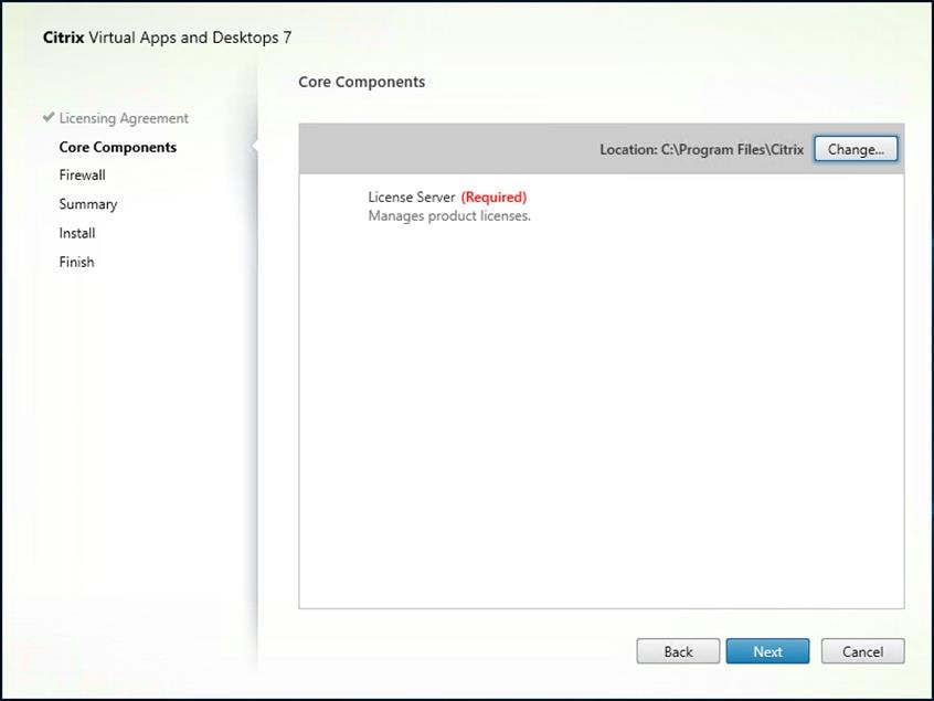
Step 7. Select the default ports and automatically configured firewall rules.
Step 8. Click Next.
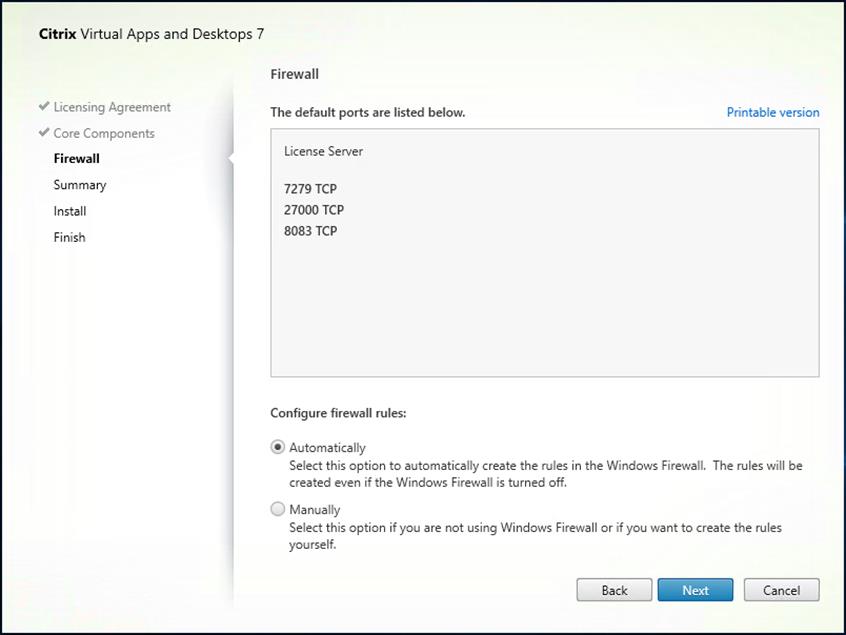
Step 9. Click Install.
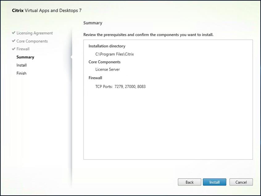
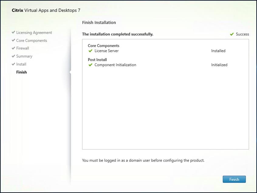
Step 10. Click Finish to complete the installation.
Procedure 2. Install Citrix Licenses
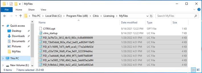
Step 1. Copy the license files to the default location (C:\Program Files (x86)\Citrix\Licensing\ MyFiles) on the license server.
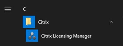
Step 2. Restart the server or Citrix licensing services so that the licenses are activated.
Step 3. Run the application Citrix License Administration Console.
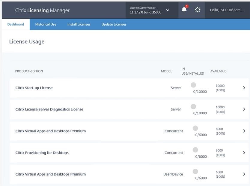
Step 4. Confirm that the license files have been read and enabled correctly.
Procedure 3. Install the Citrix Virtual Apps and Desktops
Step 1. To begin the installation, connect to the first Delivery Controller server and launch the installer from the Citrix_Virtual_Apps_and_Desktops_7_2203_4000 ISO.
Step 2. Click Start.

Step 3. The installation wizard presents a menu with three subsections. Click Get Started - Delivery Controller.
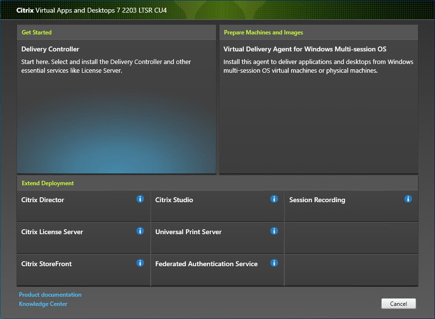
Step 4. Read the Citrix License Agreement. If acceptable, indicate your acceptance of the license by selecting I have read, understand, and accept the terms of the license agreement.
Step 5. Click Next.

Step 6. Select the components to be installed on the first Delivery Controller Server:
● Delivery Controller
● Studio
● Director
Step 7. Click Next.
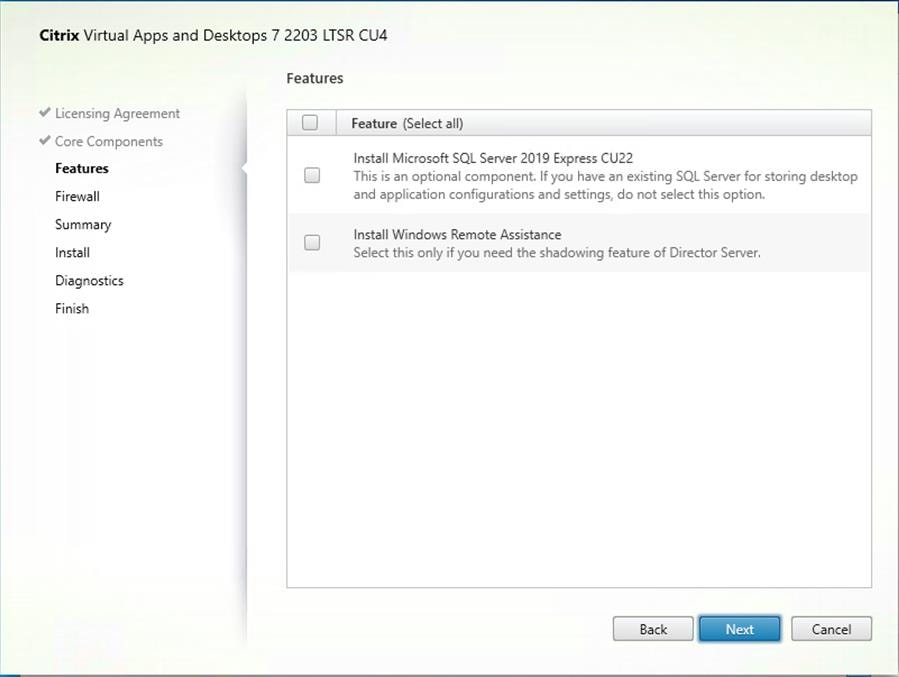
Step 8. Since a dedicated SQL Server will be used to Store the Database, leave “Install Microsoft SQL Server 2014 SP2 Express” unchecked.
Step 9. Click Next.
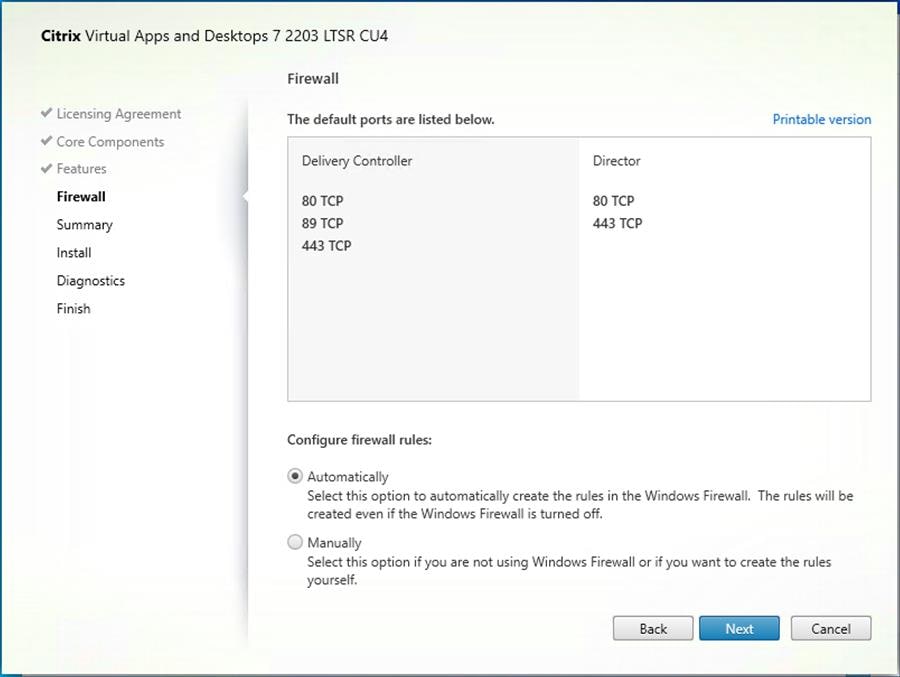
Step 10. Select the default ports and automatically configured firewall rules.
Step 11. Click Next.
Step 12. Click Install to begin the installation.

Note: Multiple reboots may be required to finish installation.
Step 13. Optional: Check Collect diagnostic information/Call Home participation.
Step 14. Click Next.
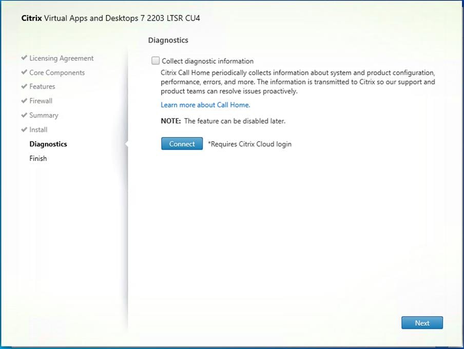
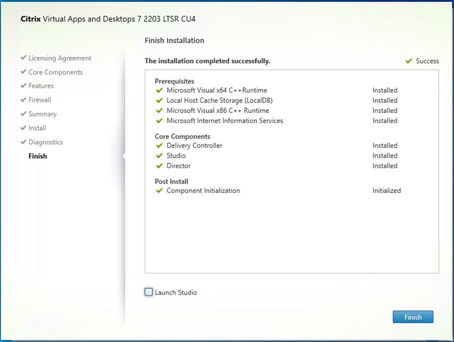
Step 15. Click Finish to complete the installation.
Step 16. Optional: Check Launch Studio to launch the Citrix Studio Console.
Procedure 4. Nutanix AHV Plug-in for Citrix Virtual Apps and Desktops
Nutanix AHV Plug-in for Citrix is designed to create and manage VDI VMs in a Nutanix Acropolis infrastructure environment. The plug-in is developed based on the Citrix defined plug-in framework and must be installed on a Delivery Controller or hosted Provisioning Server. Additional details on AHV Plug-in for Citrix can be found here.
Step 1. Download the latest version of the Nutanix AHV Plug-in for Citrix installer MSI (.msi) file NutanixAHV_Citrix_Plugin.msi from the Nutanix Support Portal.
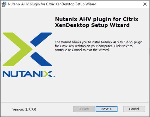
Step 2. Double-click the NutanixAHV_Citrix_Plugin.msi installer file to start the installation wizard. In the welcome window, click Next.
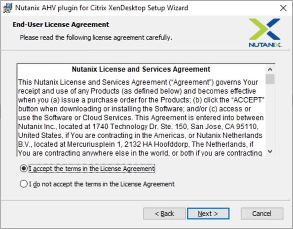
Step 3. The End-User License Agreement details the software license agreement. To proceed with the installation, read the entire agreement, select I accept the terms in the license agreement and click Next.
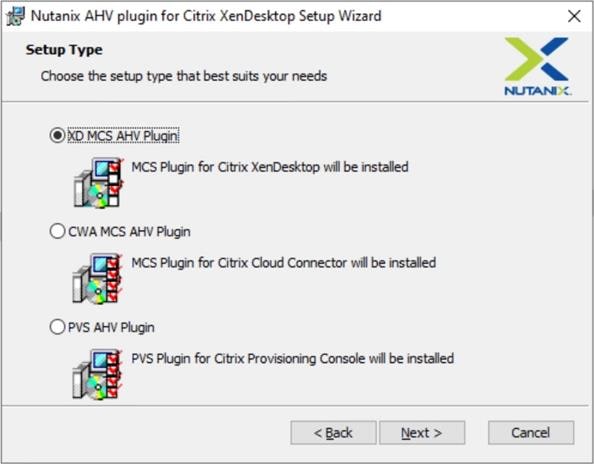
Step 4. Select the XD MCS AHV Plugin in the Setup Type dialog box and click Next.
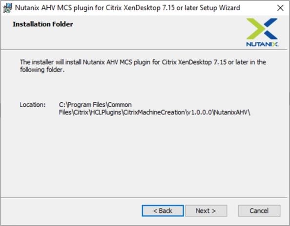
Step 5. Click Next to confirm installation folder location.
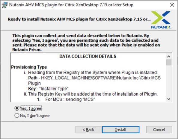
Step 6. Select Yes, I agree at the Data Collection dialog box of the installation wizard to allow collection and transmission. Click Install to start the plug-in installation.
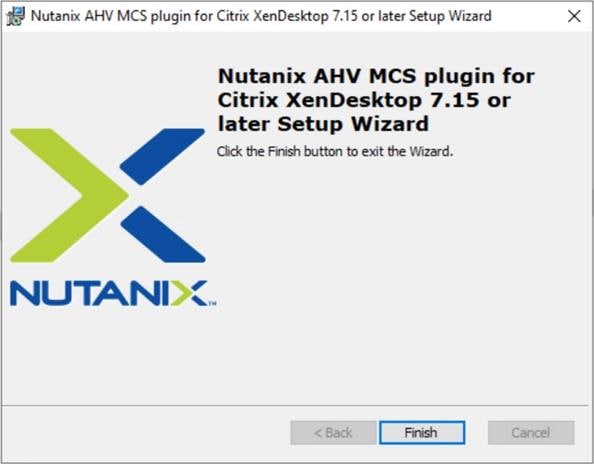
Step 7. Click Finish to complete Installation.
Citrix Studio is a management console that allows you to create and manage infrastructure and resources to deliver desktops and applications. It provides wizards to set up your environment, create workloads to host applications and desktops and assign applications and desktops to users.
Citrix Studio launches automatically after the Delivery Controller installation, or it can be launched manually if necessary. Studio is used to create a Site, which is the core of the Citrix Virtual Apps and Desktops environment consisting of the Delivery Controller and the Database.
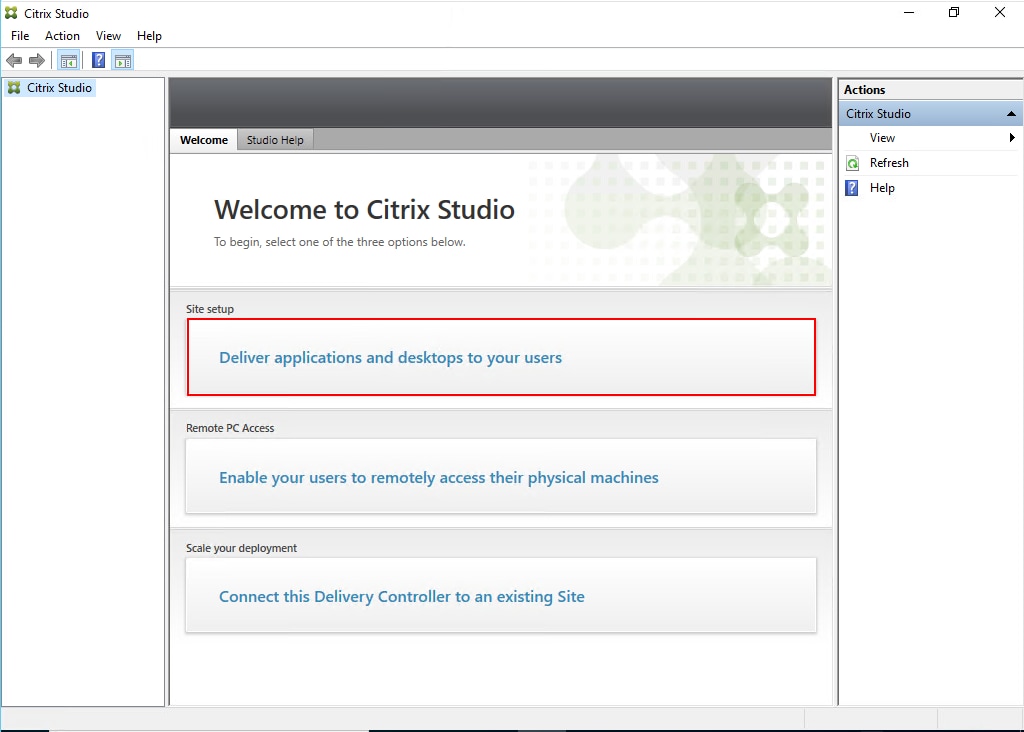
Step 1. From Citrix Studio, click Deliver applications and desktops to your users.
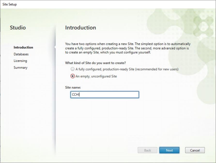
Step 2. Select the An empty, unconfigured Site radio button. Enter a site name and click Next.
.
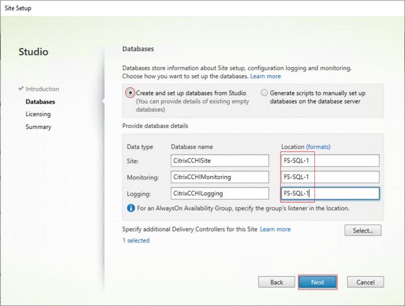
Step 3. Provide the Database Server Locations for each data type. Click Next.
Note: For an SQL AlwaysOn Availability Group, use the group’s listener DNS name.
Note: Additional controllers can be added later.
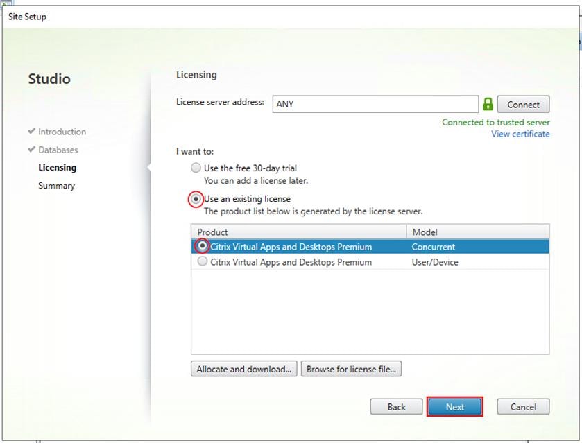
Step 4. Provide the FQDN of the license server.
Step 5. Click Connect to validate and retrieve any licenses from the server.
Note: If no licenses are available at this time, you can use the 30-day free trial or activate a license file.
Step 6. Select the appropriate product edition using the license radio button.
Step 7. Click Next.
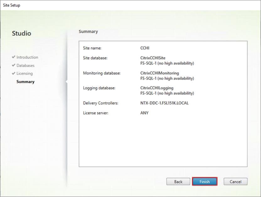
Step 8. Verify information on the Summary page. Click Finish.
.
Procedure 6. Configure the Citrix Virtual Apps and Desktops Site Hosting Connection
Step 1. Go to Configuration > Hosting in Studio, click Add Connection and Resources.
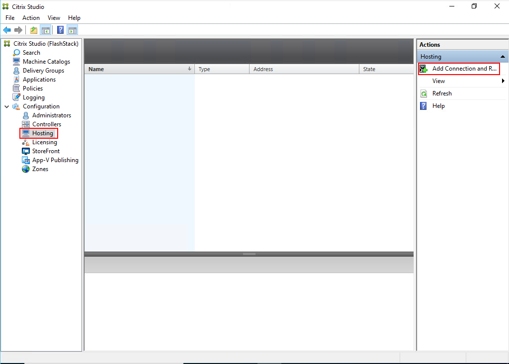
Step 2. On the Connection page:
● Select the Connection type of Nutanix AHV.
● Nutanix cluster virtual IP address (VIP).
● Enter the username.
● Provide the password for the admin account.
● Provide a connection name.
● Select the tool to create virtual machines: Machine Creation Services or Citrix Provisioning.
Step 3. Click Next.

Step 4. Select the Network to be used by this connection and click Next.
.
Step 5. Review the Add Connection and Recourses Summary and click Finish.
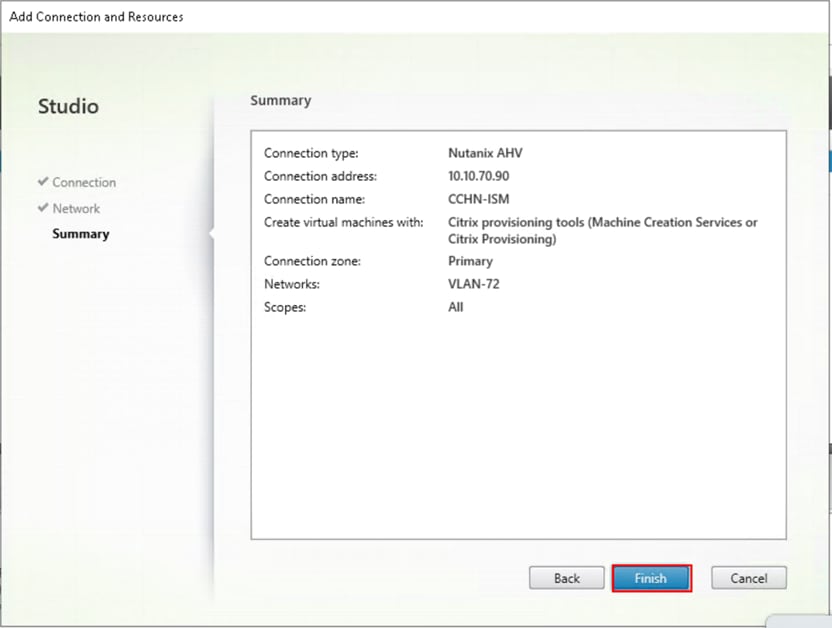
Procedure 7. Configure the Citrix Virtual Apps and Desktops Site Administrators
Step 1. Connect to the Citrix Virtual Apps and Desktops server and open the Citrix Studio Management console.
Step 2. From the Configuration menu, right-click Administrator and select Create Administrator from the drop-down list.
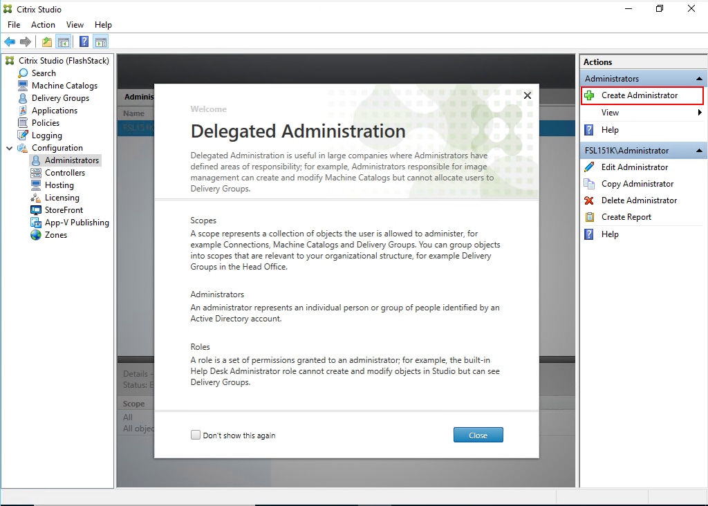
Step 3. Select or Create the appropriate scope and click Next.
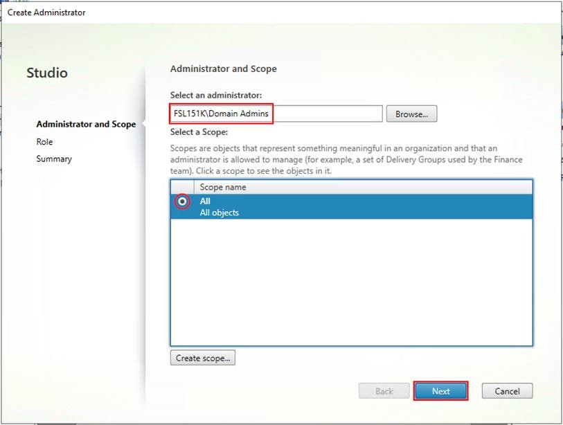
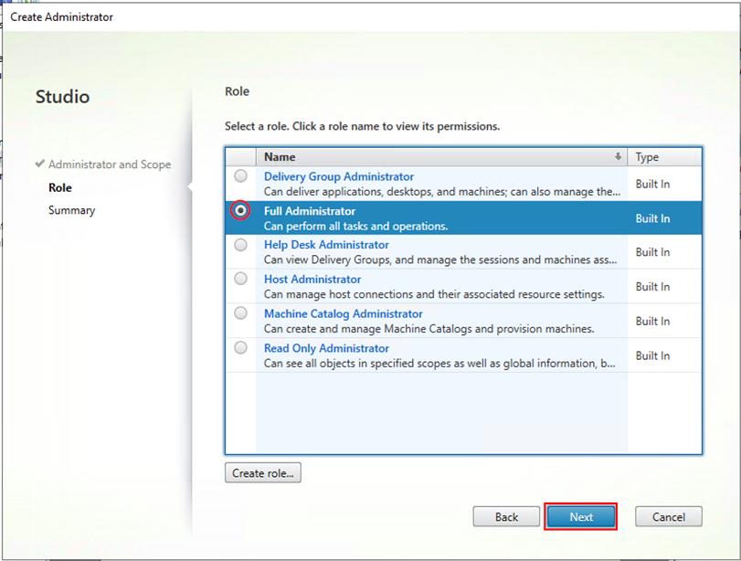
Step 4. Select an appropriate Role.
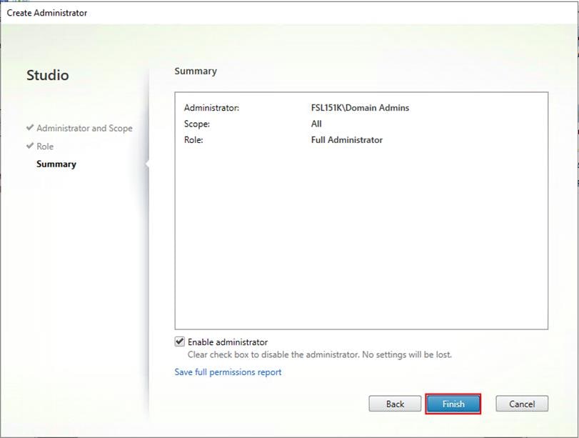
Step 5. Review the Summary, check Enable administrator and click Finish.
Procedure 8. Install the Citrix Virtual Apps and Desktops on the additional controller
Note: After the first controller is completely configured and the Site is operational, you can add additional controllers. In this CVD, we created two Delivery Controllers.
Step 1. To begin installing the second Delivery Controller, connect to the second server virtual machine and launch the installer from the Citrix_Virtual_Apps_and_Desktops_7_2203_4000 ISO.
Step 2. Click Start.
Step 3. Click Delivery Controller.
Step 4. Repeat the same steps used to install the first Delivery Controller; Install the Citrix Virtual Apps and Desktops, including the AHV Plugin for Citrix.
Step 5. Review the Summary configuration and click Finish.
Step 6. Open Citrix Studio.
Step 7. From Citrix Studio, click Connect this Delivery Controller to an existing Site. Follow the prompts to complete this procedure.
Procedure 9. Install and Configure StoreFront
Citrix StoreFront stores aggregate desktops and applications from Citrix Virtual Apps and Desktops sites, making resources readily available to users. In this CVD, we created two StoreFront servers on dedicated virtual machines.
Step 1. To begin the installation of the StoreFront, connect to the first StoreFront server and launch the installer from the Citrix_Virtual_Apps_and_Desktops_7_2203_4000 ISO.
Step 2. Click Start.

Step 3. Click Extend Deployment Citrix StoreFront.
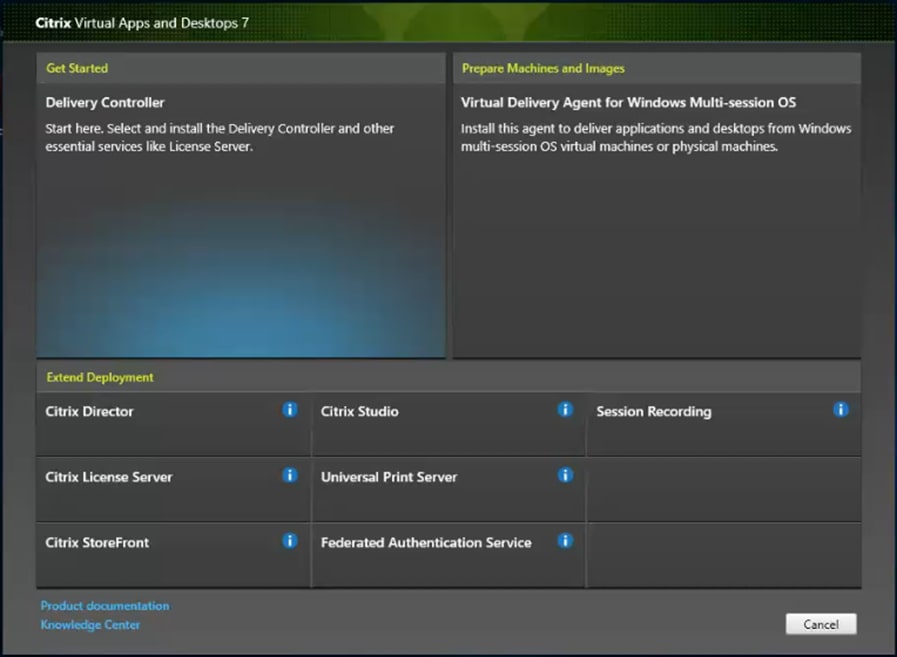
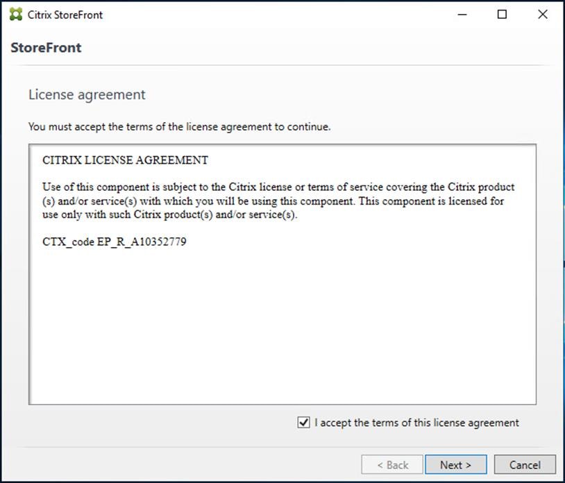
Step 4. Indicate your acceptance of the license by selecting I have read, understand, and accept the terms of the license agreement.
Step 5. Click Next.
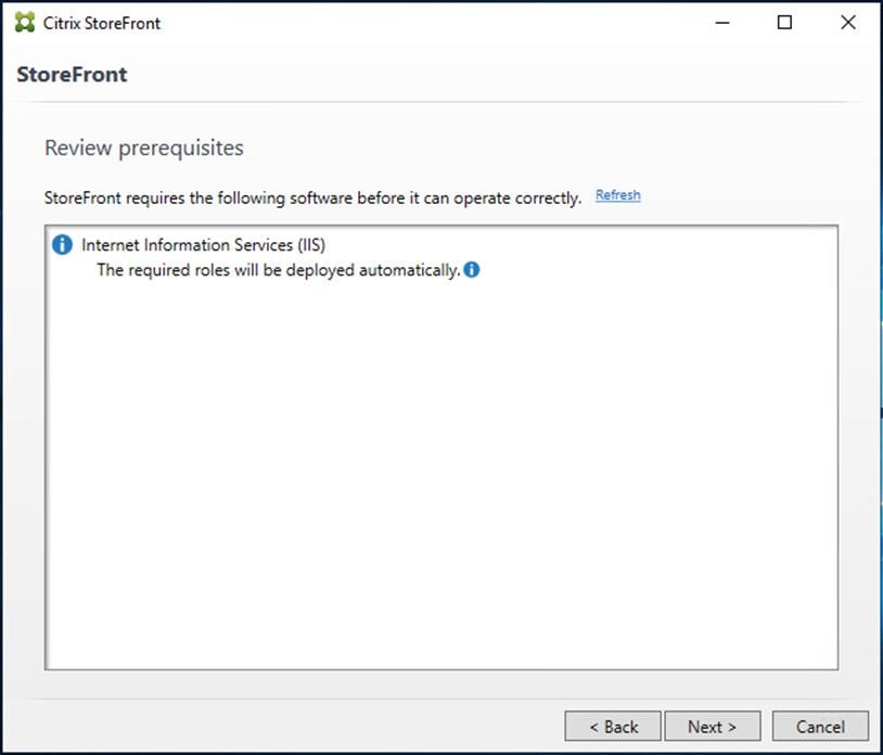
Step 6. On the Prerequisites page click Next.
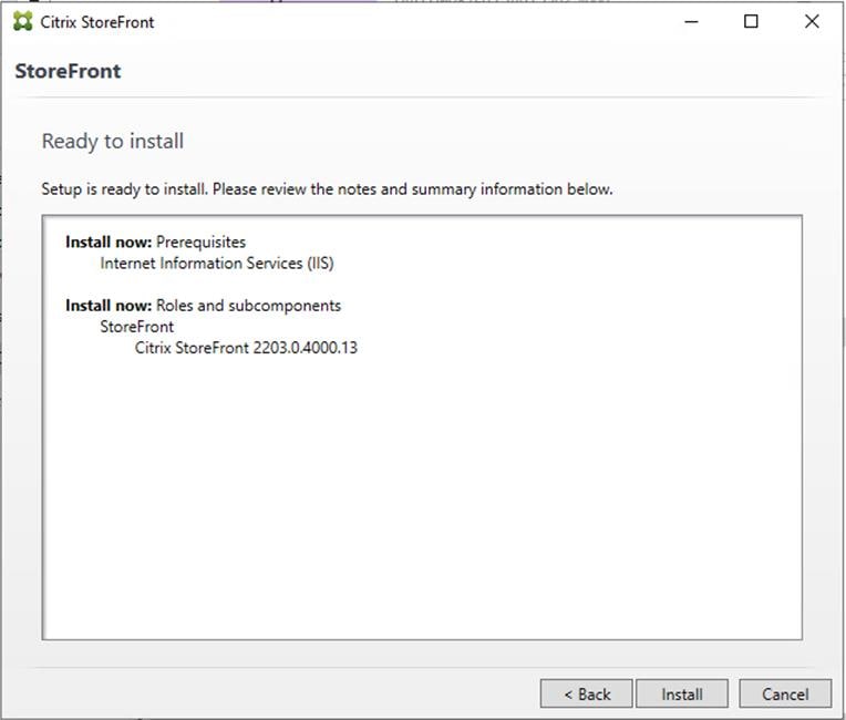
Step 7. Click Install.
Step 8. Click Finish.

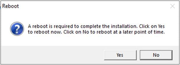
Step 9. Click Yes to reboot the server.
Step 10. Open the StoreFront Management Console.
Step 11. Click Create a new deployment.

Step 12. Specify a name for your Base URL.
Step 13. Click Next.

Step 14. For a multiple server deployment, use the load balancing environment in the Base URL box.
Step 15. Click Next.
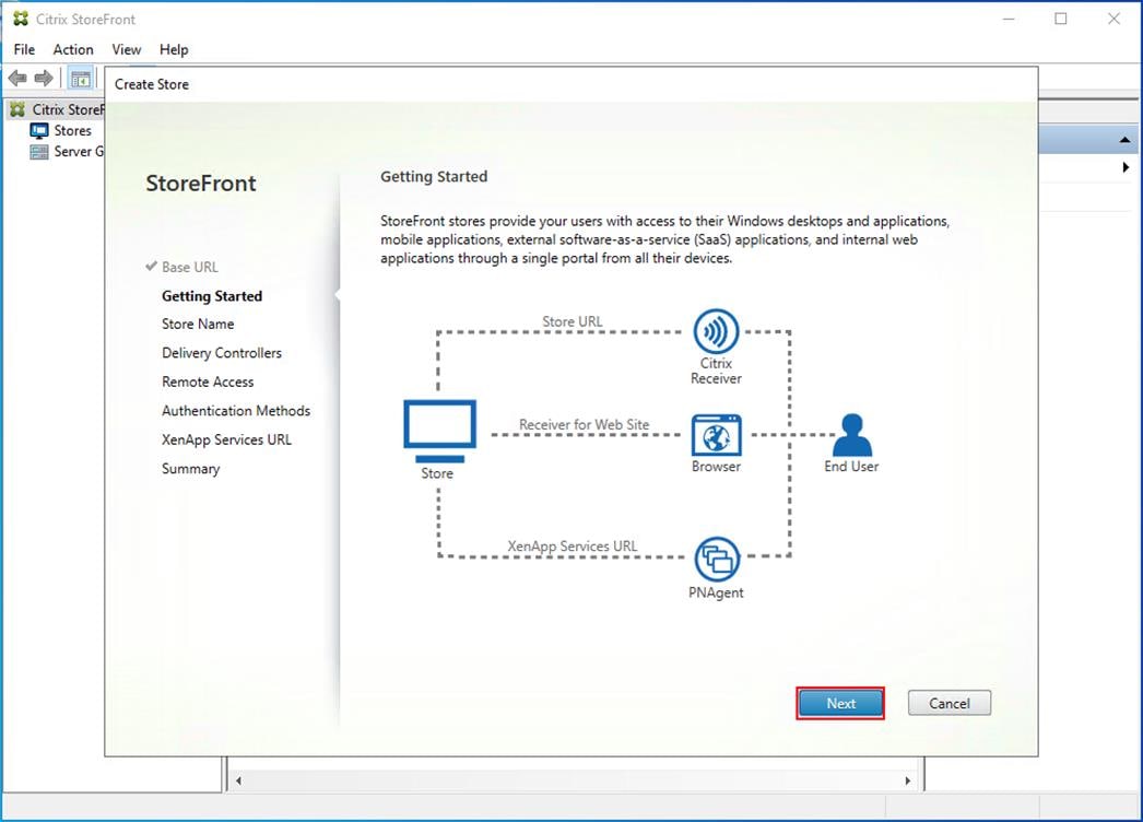
Step 16. Specify a name for your store.

Step 17. Click Add to specify Delivery controllers for your new Store.

Step 18. Add the required Delivery Controllers to the store.
Step 19. Click OK.
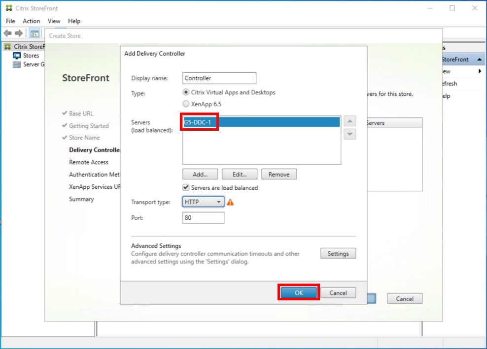
Step 20. Click Next.

Step 21. Specify how connecting users can access the resources, in this environment only local users on the internal network are able to access the store.
Step 22. Click Next.

Step 23. From the Authentication Methods page, select the methods your users will use to authenticate to the store. The following methods were configured in this deployment:
● Username and password: Users enter their credentials and are authenticated when they access their stores.
● Domain passthrough: Users authenticate to their domain-joined Windows computers and their credentials are used to log them on automatically when they access their stores.
Step 24. Click Next.
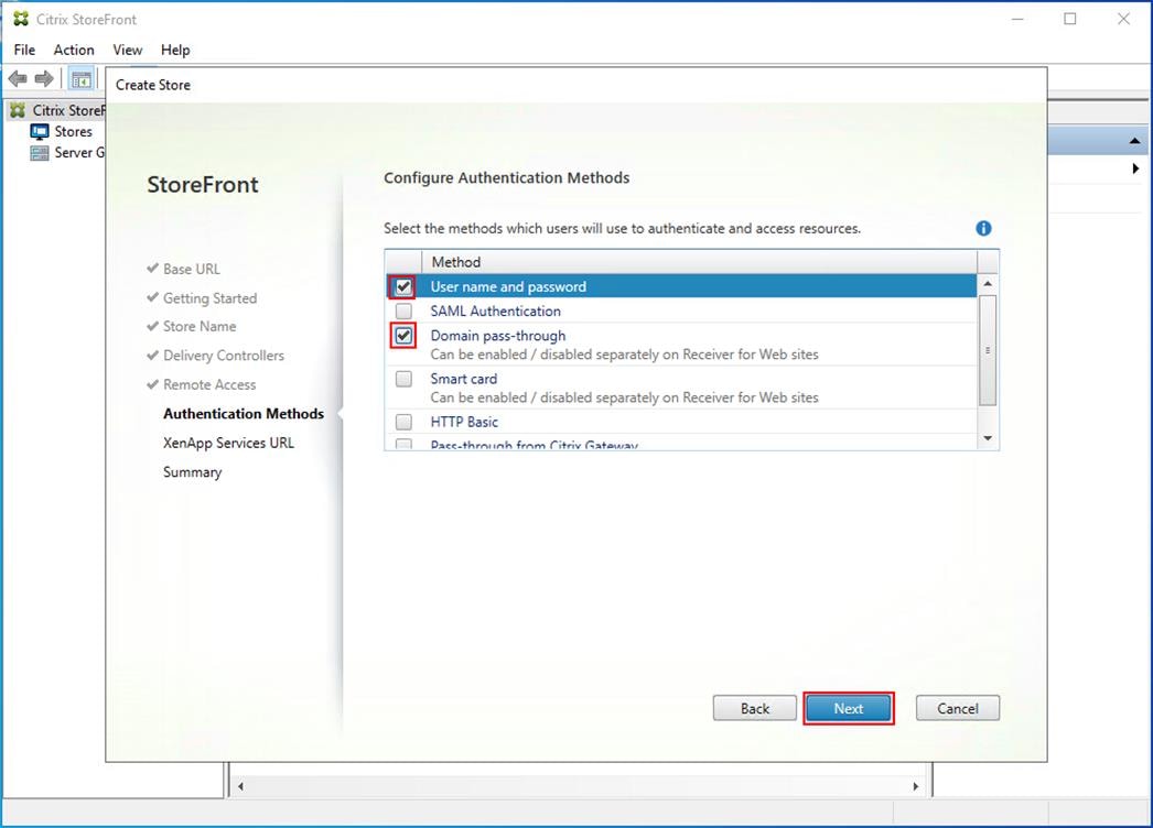
Step 25. Configure the XenApp Service URL for users who use PNAgent to access the applications and desktops.
Step 26. Click Create.

Step 27. After creating the store click Finish.

Procedure 10. Configure Additional StoreFront Servers
After the first StoreFront server is completely configured and the Store is operational, you can add additional servers.
Step 1. Install the second StoreFront using the same installation steps in Procedure 9 Install and Configure Storefront.
Step 2. Connect to the first StoreFront server.
Step 3. To add the second server and generate the authorization information that allows the additional StoreFront server to join the server group, select Add Server the Actions pane in the Server Group.
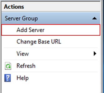
Step 4. Copy the authorization code.
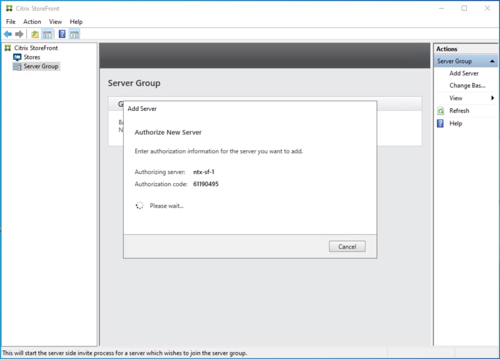
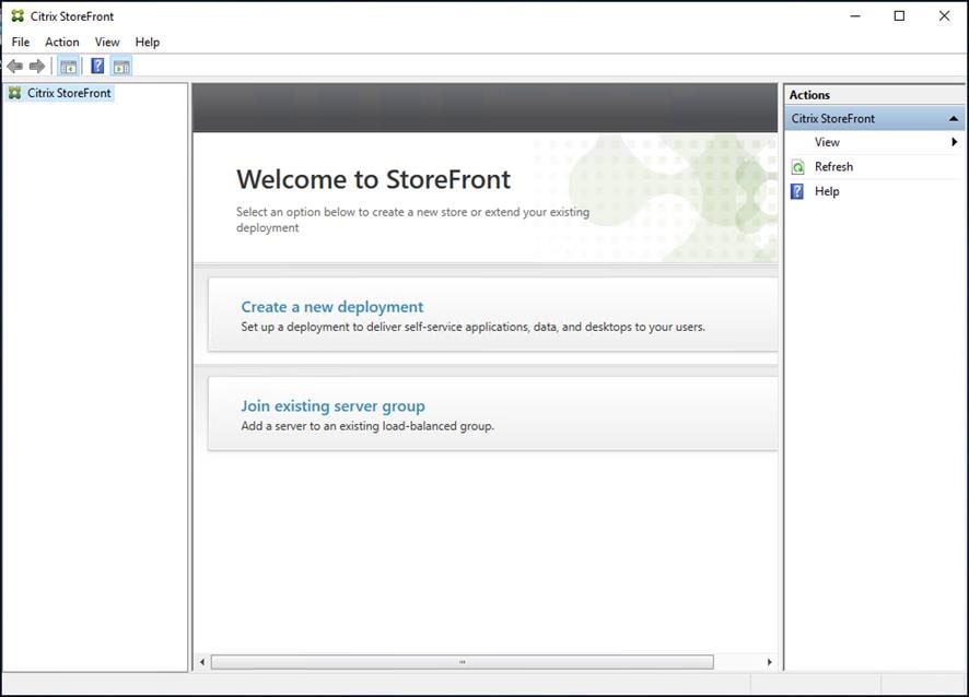
Step 5. From the StoreFront Console on the second server select Join existing server group.
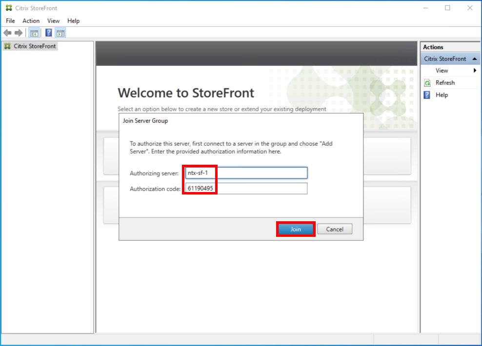
Step 6. In the Join Server Group dialog, enter the name of the first Storefront server and paste the Authorization code into the Join Server Group dialog.
Step 7. Click Join.
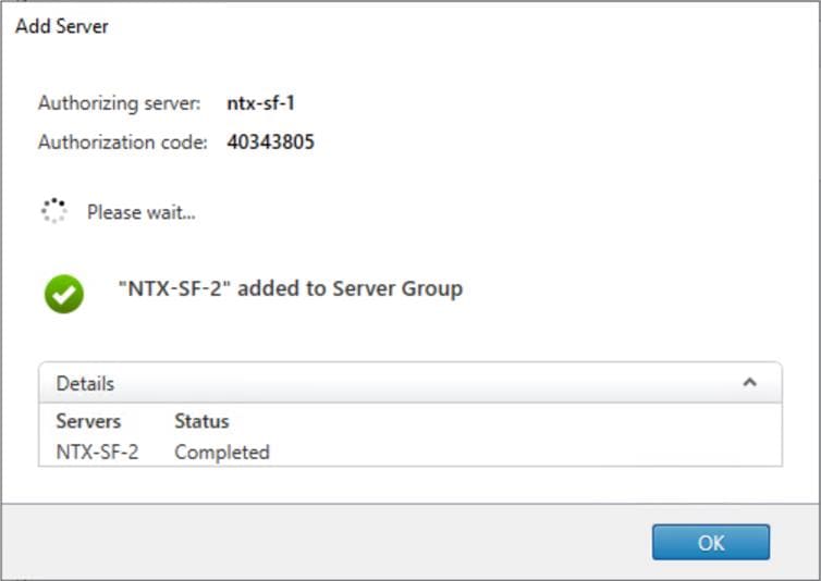
A message appears when the second server has joined successfully.
Step 8. Click OK.
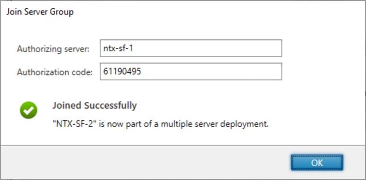
The second StoreFront is now in the Server Group.
Install and Configure Citrix Provisioning Server
In most implementations, there is a single vDisk providing the standard image for multiple target devices. Thousands of target devices can use a single vDisk shared across multiple Provisioning Services (PVS) servers in the same farm, simplifying virtual desktop management. This section describes the installation and configuration tasks required to create a PVS implementation.
The PVS server can have many stored vDisks, and each vDisk can be several gigabytes in size. Your streaming performance and manageability can be improved using high-performance storage solutions. PVS software and hardware requirements are available in the Provisioning Services 2203 LTSR document.
Procedure 1. Configure Prerequisites
Step 1. Set the following Scope Options on the DHCP server hosting the PVS target machines:

Step 2. Create a DNS host records with multiple PVS Servers IP for TFTP Load Balancing:

Note: Only one MS SQL database is associated with a farm. You can choose to install the Provisioning Services database software on an existing SQL database server, if that machine can communicate with all Provisioning Servers within the farm or create new.
Note: Microsoft SQL 2019 was installed separately for this CVD.
Procedure 2. Install and Configure Citrix Provisioning Service
Step 1. Connect to Citrix Provisioning server and launch Citrix Provisioning Services 2203 LTSR ISO and let AutoRun launch the installer.
Step 2. Click Console Installation.
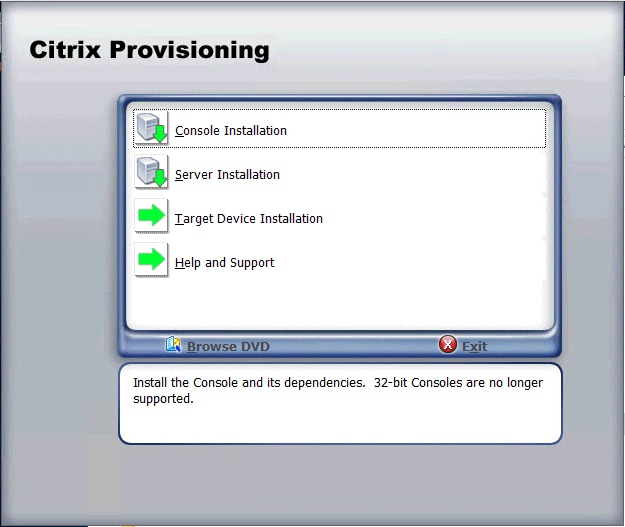
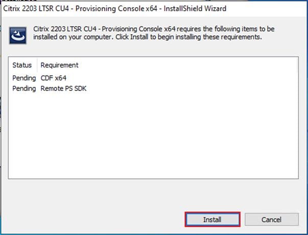
Step 3. Click Install to start the console installation.
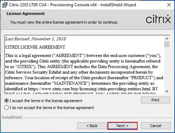
Step 4. Click Next.

Step 5. Read the Citrix License Agreement. If acceptable, select I accept the terms in the license agreement.
Step 6. Click Next.
Step 7. Optional: provide User Name and Organization.
Step 8. Click Next.
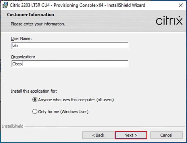
Step 9. Accept the default path.
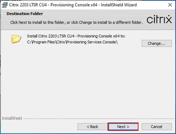
Step 10. Click Install.

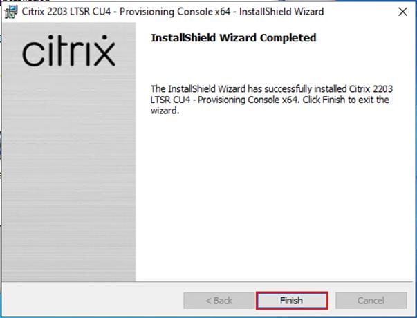
Step 11. Click Finish after successful installation.
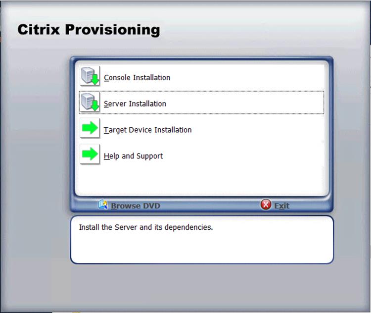
Step 12. From the main installation screen, select Server Installation.
Step 13. Click Install on the prerequisites dialog.

Step 14. When the installation wizard starts, click Next.
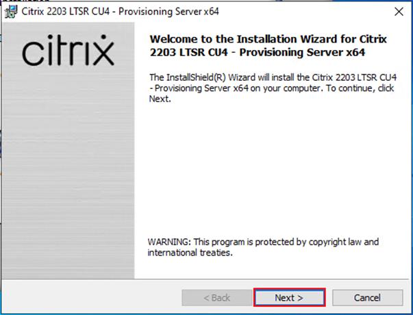
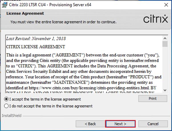
Step 15. Review the license agreement terms. If acceptable, select I accept the terms in the license agreement.
Step 16. Click Next.
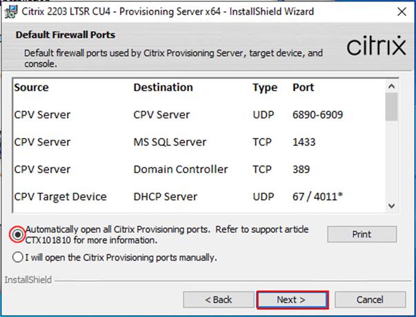
Step 17. Select Automatically open Citrix PVS Firewall Ports.
Step 18. Provide User Name and Organization information. Select who will see the application.
Step 19. Click Next.

Step 20. Accept the default installation location.
Step 21. Click Next.

Step 22. Click Install to begin the installation.
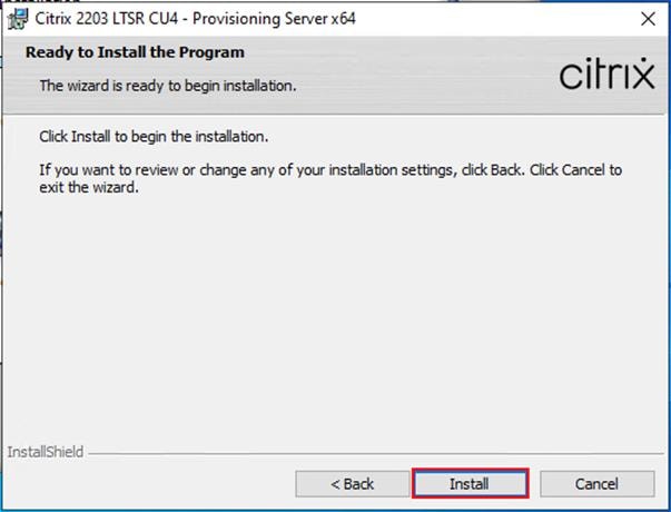
Step 23. Click Finish when the install is complete.

Procedure 3. Configure Citrix Provisioning
Note: If Citrix Provisioning services configuration wizard doesn’t start automatically, follow these steps:
Step 1. Start the PVS Configuration Wizard.

Step 2. Click Next.

Step 3. Since the PVS server is not the DHCP server for the environment, select The service that runs on another computer.
Step 4. Click Next.

Step 5. Since DHCP boot options are used for TFTP services, select The service that runs on another computer.
Step 6. Click Next.

Step 7. Since this is the first server in the farm, select Create farm.
Step 8. Click Next.

Step 9. Enter the FQDN of the SQL server.
Step 10. Click Next.

Step 11. Provide the Database, Farm, Site, and Collection name.
Step 12. Click Next.

Step 13. Provide the vDisk Store details.
Step 14. Click Next.

Note: For large-scale PVS environment, it is recommended to create the share using support for CIFS/SMB3 on an enterprise-ready File Server, such as Nutanix Files SMB shares.
Step 15. Provide the FQDN of the license server.
Step 16. Optional: provide a port number if changed on the license server.
Step 17. Click Next.

Step 18. If an Active Directory service account is not already setup for the PVS servers, create that account before clicking Next on this dialog.
Step 19. Select Specified user account.
Step 20. Complete the User name, Domain, Password, and Confirm password fields, using the PVS account information created earlier.
Step 21. Click Next.

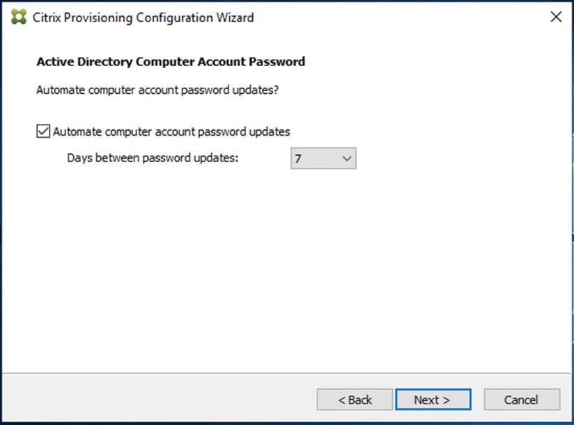
Step 22. Set the Days between password updates to 7.
Note: This will vary per environment. “7 days” for the configuration was appropriate for testing purposes.
Step 23. Click Next.

| Tech tip |
| This setting requires the Group Policy Object (GPO) where the target device is located for the policy Disable machine account password changes to be enabled. Refer to the Citrix documentation for more details. |
Step 24. Keep the defaults for the network cards.
Step 25. Click Next.

Step 26. Select Use the Provisioning Services TFTP service.
Step 27. Click Next.

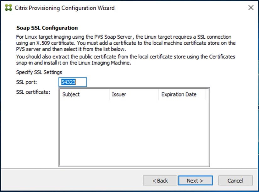
Step 28. If Soap Server is used, provide the details.
Step 29. Click Next.

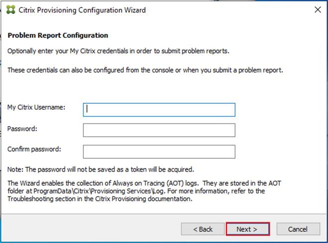
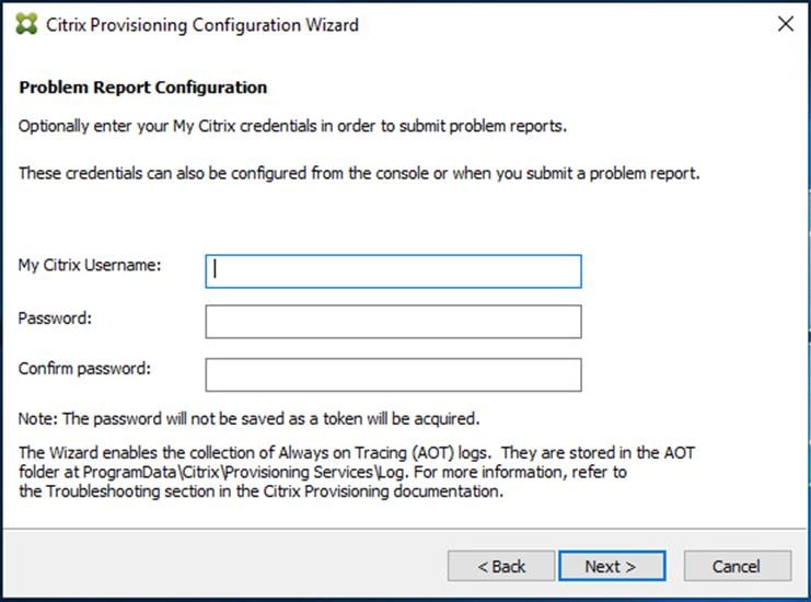
Step 30. If desired, fill in Problem Report Configuration.
Step 31. Click Next.
Step 32. Click Finish to start the installation.
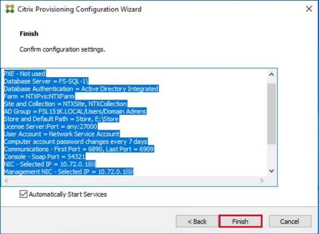
Step 33. When the installation is completed, click Done.

Procedure 4. Install Additional PVS Servers
Complete the installation steps on the additional PVS servers up to the configuration step, where it asks to Create or Join a farm. In this CVD, we repeated the procedure to add a total of two PVS servers.
Step 1. On the Farm Configuration dialog, select Join existing farm.
Step 2. Click Next.

Step 3. Provide the FQDN of the SQL Server and select appropriate authentication method
Step 4. Click Next.

Step 5. Accept the Farm Name.
Step 6. Click Next.

Step 7. Accept the Existing Site.
Step 8. Click Next.
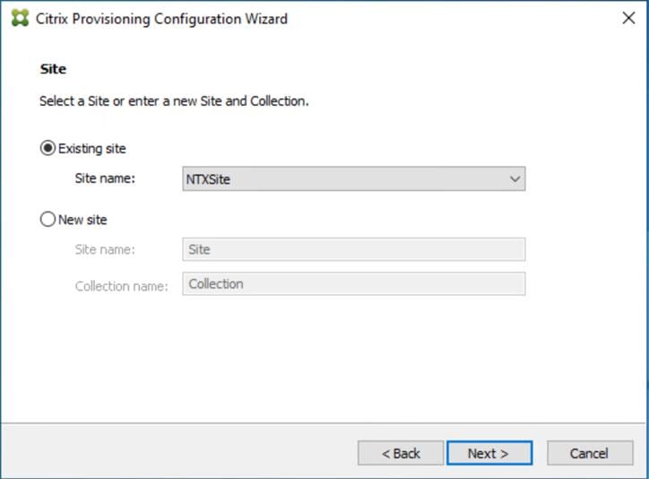
Step 9. Accept the existing vDisk store.
Step 10. Click Next.
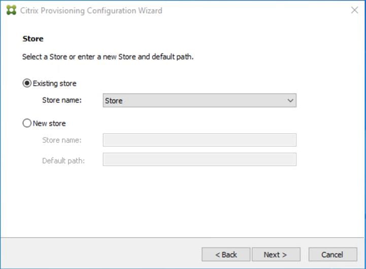
Step 11. Provide the FQDN of the license server.
Step 12. Optional: provide a port number if changed on the license server.
Step 13. Click Next.
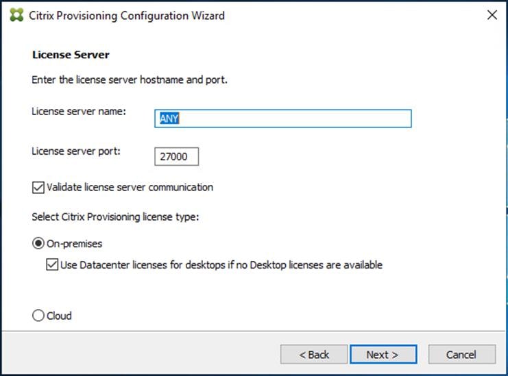
Step 14. Provide the PVS service account information.
Step 15. Click Next.

Step 16. Set the Days between password updates to 7.
Step 17. Click Next.
Step 18. Accept the network card settings.
Step 19. Click Next.

Step 20. Check the box for Use the Provisioning Services TFTP service.
Step 21. Click Next.

Step 22. Click Next.

Step 23. If Soap Server is used, provide details.
Step 24. Click Next.
Step 25. If desired, fill in Problem Report Configuration.
Step 26. Click Next.
Step 27. Click Finish to start the installation process.
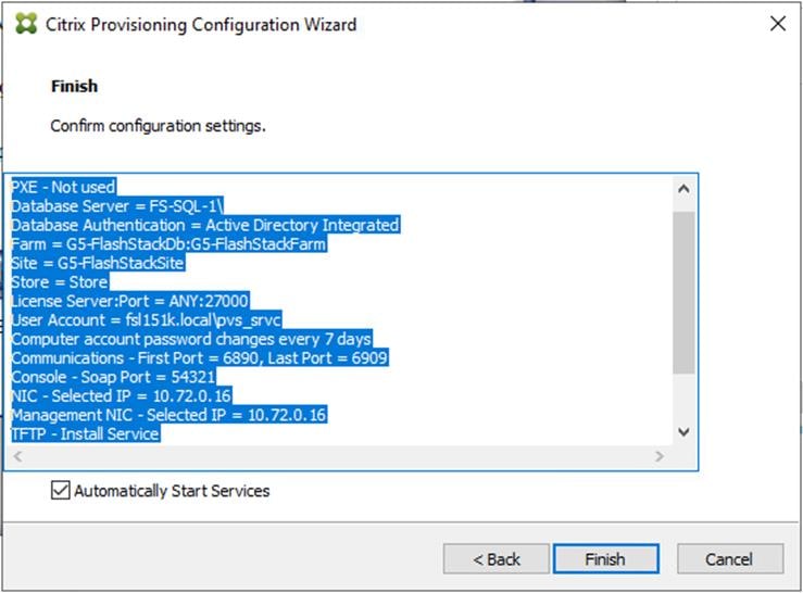
Step 28. Click Done when the installation finishes.
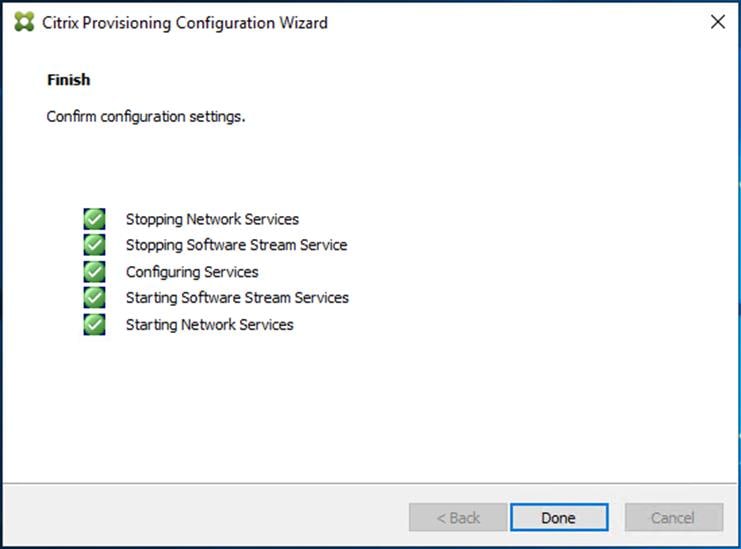
Note: Optionally, you can install the Provisioning Services console on the second PVS server following the procedure in the section Installing Provisioning Services.
Step 29. After installing the one additional PVS server, launch the Provisioning Services Console to verify that the PVS Servers and Stores are configured and that DHCP boot options are defined.
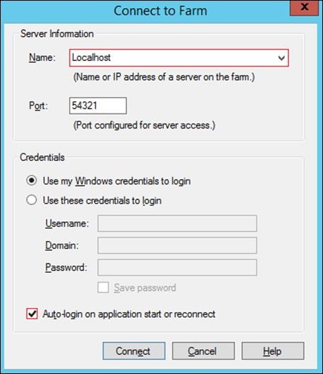
Step 30. Launch the Provisioning Services Console and select Connect to Farm.

Step 31. Enter localhost for the PVS1 server.
Step 32. Click Connect.
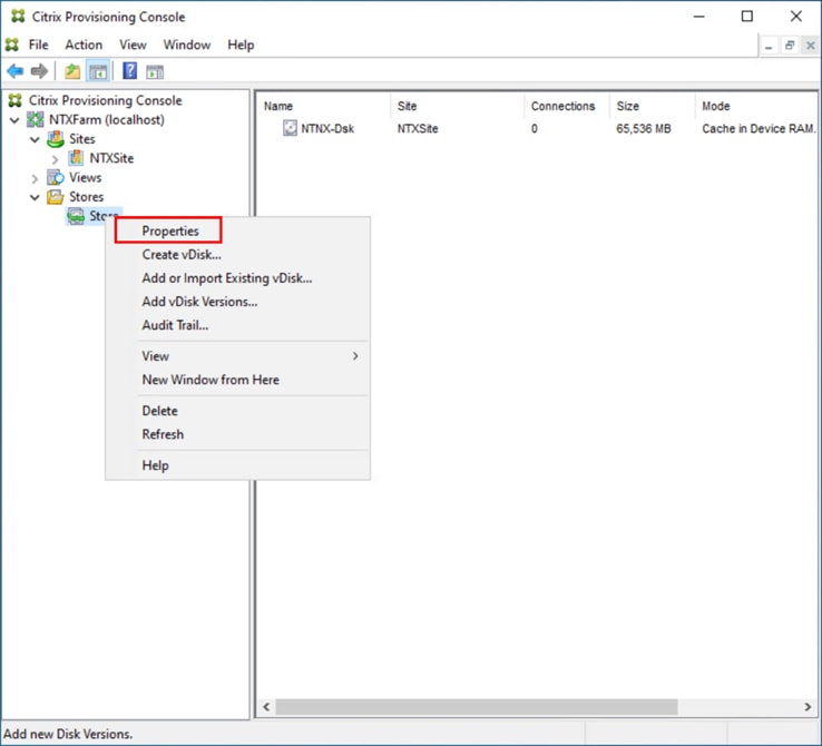
Step 33. Select Store Properties from the drop-down list.
Step 34. In the Store Properties dialog, add the Default store path to the list of Default write cache paths. Click OK.
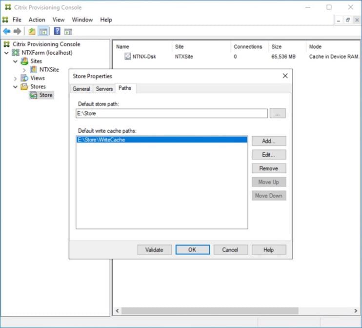
Step 35. Synchronize vDisk between the Local Stores of the Provisioning Service Servers using robocopy:
robocopy <sourcepath> <destinationpath> /xo vdiskname.*
Note: Using a central storage solution for vDisks in a Citrix PVS environments can offer several compelling advantages in ease of management, scalability, and performance compared to the Local PVS store. Using Nutanix Files for PVS vDisk storage can significantly enhance the efficiency and reliability of your provisioning services.
Step 36. Select Load Balancing from the vDisk drop-down list
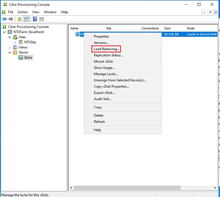
Step 37. Verify the vDisk is load balanced.
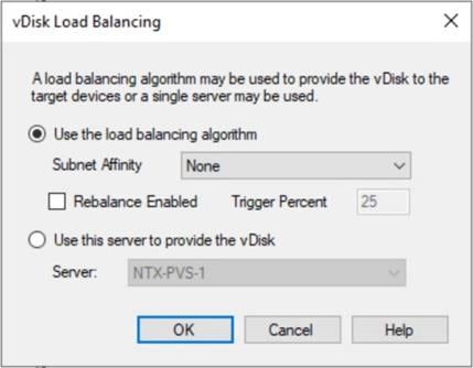
Procedure 5. Nutanix AHV Plug-in for Citrix Provisioning Services
Nutanix AHV Plug-in for Citrix is designed to create and manage VDI VMs in a Nutanix Acropolis infrastructure environment. The plug-in is developed based on the Citrix defined plug-in framework and must be installed on a Delivery Controller or Provisioning Server is hosted. Additional details on AHV Plug-in for Citrix can be found here.
Step 1. Download the latest version of the Nutanix AHV Plug-in for Citrix installer MSI (.msi) file NutanixAHV_Citrix_Plugin.msi from the Nutanix Support Portal.
Step 2. Double-click the NutanixAHV_Citrix_Plugin.msi installer file to start the installation wizard. At the welcome window, click Next.
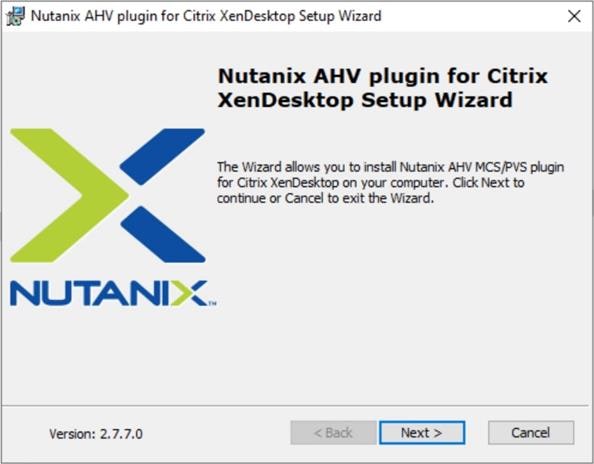
Step 3. The End-User License Agreement screen details the software license agreement. To proceed with the installation, read the entire agreement, select I accept the terms in the license agreement and click Next.
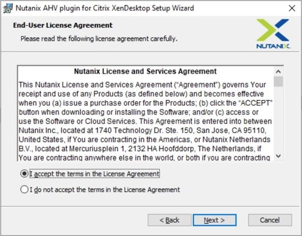
Step 4. Select the PVS AHV Plugin in the Setup Type dialog box and click Next.

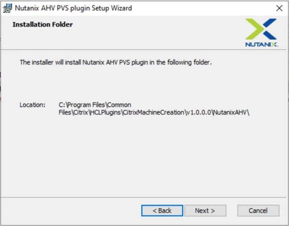
Step 5. Click Next to confirm installation folder location.
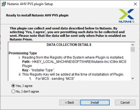
Step 6. Select Yes, I agree at the Data Collection dialog box of the installation wizard to allow collection and transmission. Click Install.
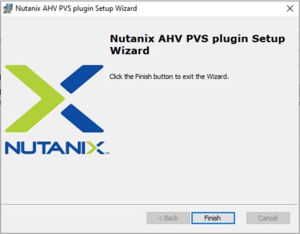
Step 7. Click Finish to complete the installation.
Provision Virtual Desktop Machines
This chapter contains the following:
● Citrix Provisioning Services
● Citrix Machine Creation Services
● Citrix Virtual Apps and Desktops Policies and Profile Management
This section provides the procedures for Citrix Provisioning Service.
Procedure 1. Citrix Provisioning Services Citrix Virtual Desktop Setup Wizard - Create PVS Streamed Virtual Desktop Machines
Step 1. Create Virtual Machine without disks or NICs (Nutanix does support a single CD-ROM if attached inside the snapshot template). Make sure to select only one core per CPU.
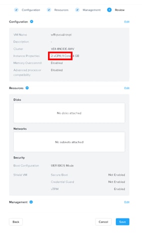
Step 2. After creating the VM (without disks or NICs), take a snapshot of the VM in the Prism Element web console.
Step 3. Start the Citrix Virtual Apps and Desktops Setup Wizard from the Provisioning Services Console.
Step 4. Right-click the Site.
Step 5. Select Citrix Virtual Desktop Setup Wizard… from the context menu.

Step 6. Click Next.

Step 7. Enter the address of the Citrix Virtual Desktop Controller that will be used for the wizard operations.
Step 8. Click Next.

Step 9. Select the Host Resources that will be used for the wizard operations.
Step 10. Click Next.

Step 11. Provide the Citrix Virtual Desktop Controller credentials.
Step 12. Click OK.

Step 13. Select the template created earlier.
Step 14. Click Next.

Step 15. Select the virtual disk (vDisk) that will be used to stream the provisioned virtual machines.
Step 16. Click Next.

Step 17. Select Create new catalog.
Step 18. Provide a catalog name.
Step 19. Click Next.

Step 20. Select Single-session OS for Machine catalog Operating System.
Step 21. Click Next.

Step 22. Select random for the User Experience.
Step 23. Click Next.

Step 24. On the Virtual machines dialog, specify the following:
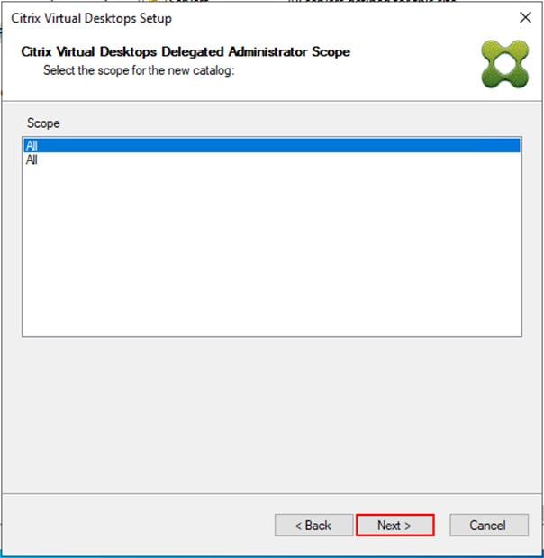
Step 25. On the Virtual machines dialog, specify the following:
● The number of virtual machines to create
Note: Create a single virtual machine at first to verify the procedure.
● 2 as Number of vCPUs for the virtual machine
● 4096 MB as the amount of memory for the virtual machine
● 10 GB as the Local write cache disk
Step 26. Click Next.
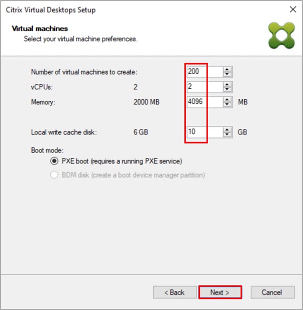
Step 27. Select AHV Container for desktop provisioning.
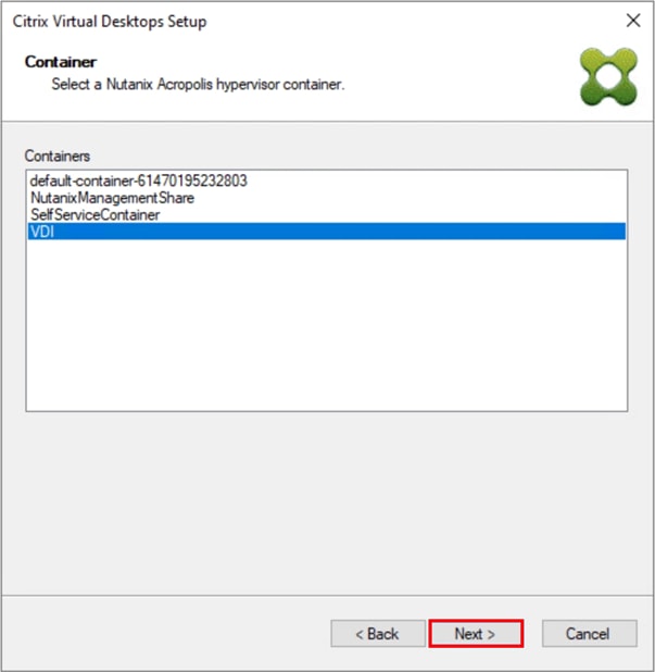
Step 28. Select Create new accounts.
Step 29. Click Next.
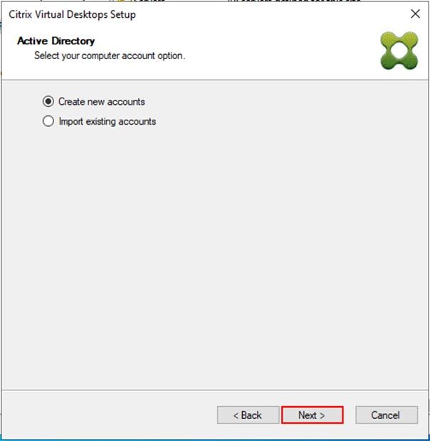
Step 30. Specify the Active Directory Accounts and Location. This is where the wizard should create computer accounts.
Step 31. Provide the Account naming scheme. An example name is shown below the naming scheme selection location in the text box.
Step 32. Click Next.

Step 33. Verify the information on the Summary screen.
Step 34. Click Finish to begin the virtual machine creation.
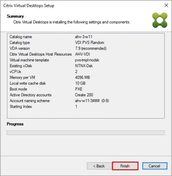
Step 35. When the wizard is done provisioning the virtual machines, click Done.
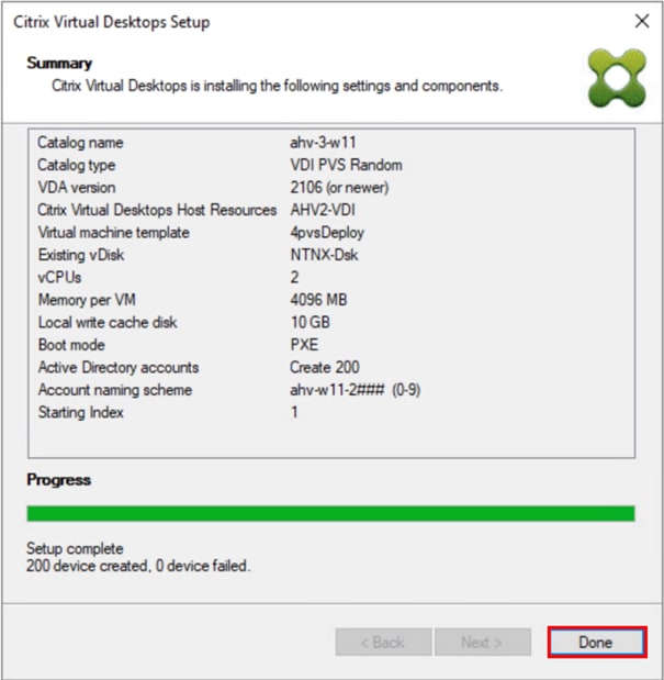
Step 36. When the wizard is done provisioning the virtual machines, verify the Machine Catalog on the Citrix Virtual Apps and Desktops Controller.
Citrix Machine Creation Services
This section provides the procedures to set up and configure Citrix Machine creation services.
Procedure 1. Machine Catalog Setup (Single-Session OS)
Step 1. Connect to a Citrix Virtual Apps and Desktops server and launch Citrix Studio.
Step 2. Select Create Machine Catalog from the Actions pane.
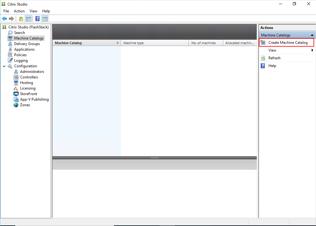
Step 3. Click Next.

Step 4. Select Single-session OS.
Step 5. Click Next.

Step 6. Select the appropriate machine management.
Step 7. Click Next.

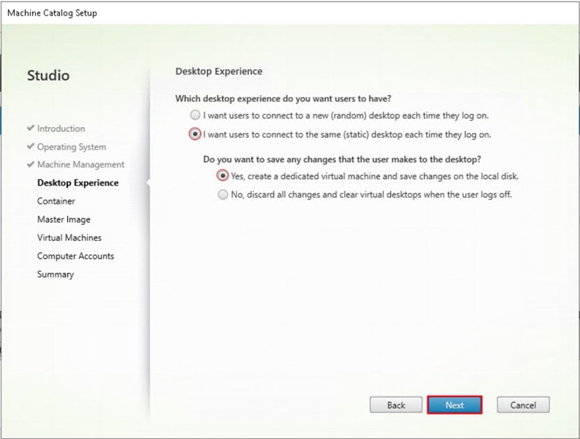
Step 8. Select (static and dedicated) for Desktop Experience.
Step 9. Click Next.
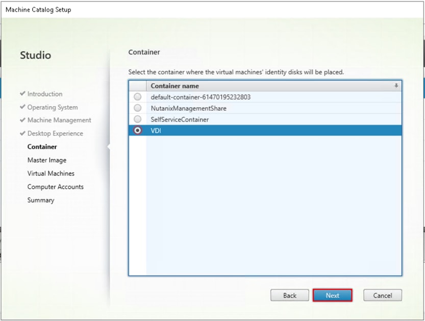
Step 10. Select the container for vDisk placement and click Next.
Step 11. Select a Virtual Machine to be used for Catalog Master Image.
Step 12. Click Next.

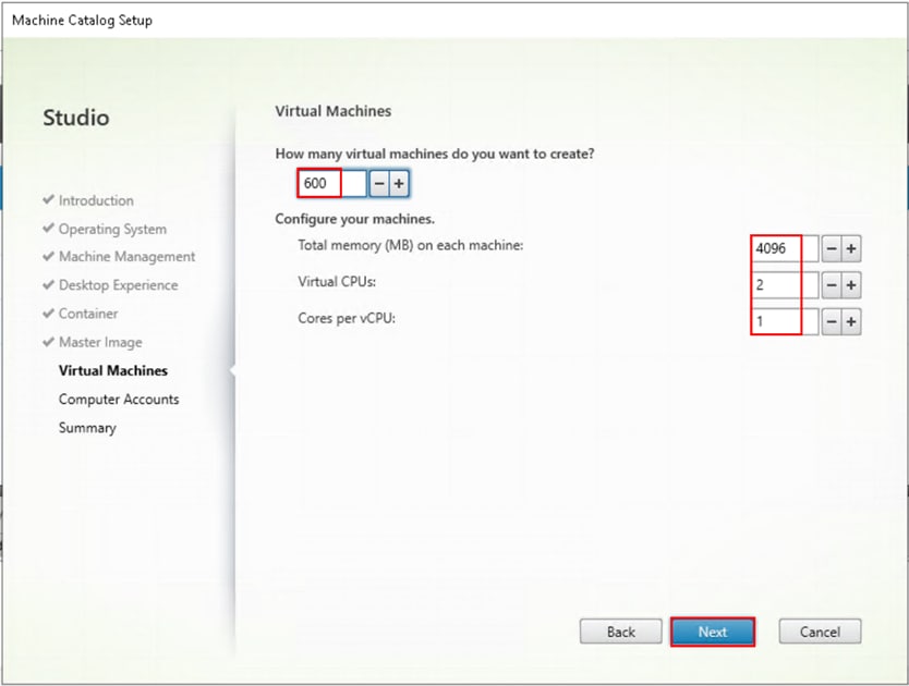
Step 13. Specify the number of desktops to create and machine configuration.
Step 14. Set amount of memory (MB) to be used by virtual desktops.
Step 15. Set vCPU and cores to be used by virtual desktops.
Step 16. Click Next.
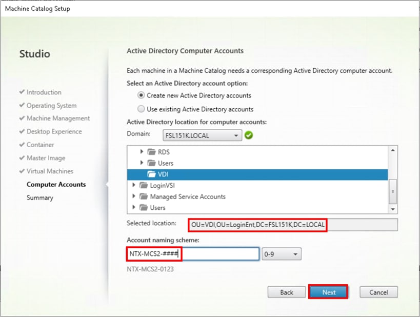
Step 17. Specify the AD account naming scheme and OU where accounts will be created.
Step 18. Click Next.
Step 19. On the Summary page specify Catalog name and click Finish to start the deployment.

Procedure 2. Machine Catalog Setup Machine (Multi-Session OS)
Step 1. Connect to a Citrix Virtual Apps and Desktops server and launch Citrix Studio.
Step 2. Select Create Machine Catalog from the Actions pane.

Step 3. Click Next.

Step 4. Select Multi-session OS.
Step 5. Click Next.

Step 6. Select the appropriate machine management.
Step 7. Click Next.

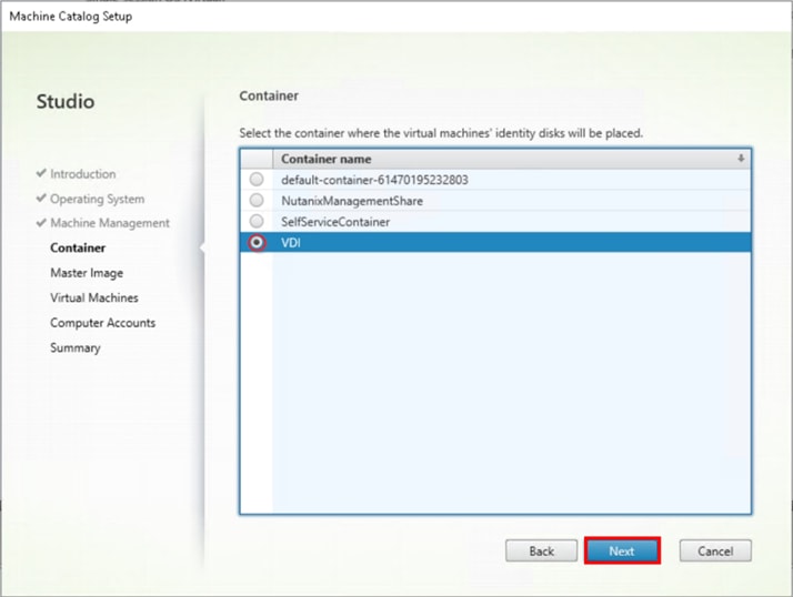
Step 8. Select Container for disk placement.
Step 9. Click Next.
Step 10. Select a Virtual Machine to be used for Catalog Master Image.
Step 11. Click Next.

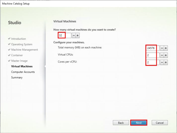
Step 12. Specify the number of desktops to create and machine configuration.
Step 13. Set the amount of memory (MB) to be used by virtual desktops.
Step 14. Select the number of vCPUs and cores.
Step 15. Click Next.
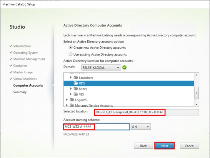
Step 16. Specify the AD account naming scheme and OU where accounts will be created.
Step 17. Click Next.
Step 18. On the Summary page specify Catalog name and click Finish to start the deployment.

Delivery Groups are collections of machines that control access to desktops and applications. With Delivery Groups, you can specify which users and groups can access which desktops and applications.
Procedure 1. Create Delivery Groups
This procedure details how to create a Delivery Group for persistent VDI desktops. When you have completed these steps, repeat the procedure for a Delivery Group for RDS desktops.
Step 1. Connect to a Citrix Virtual Apps and Desktops server and launch Citrix Studio.
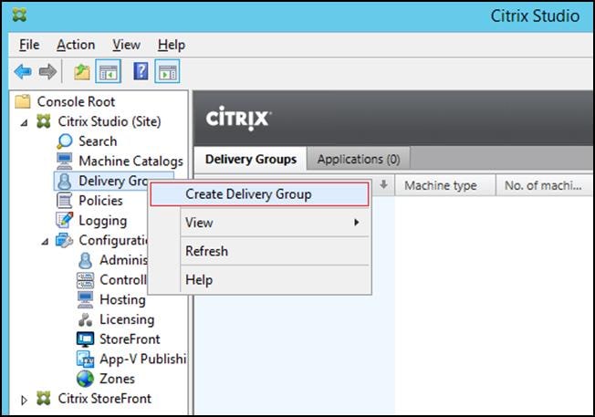
Step 2. Select Create Delivery Group from the drop-down list.
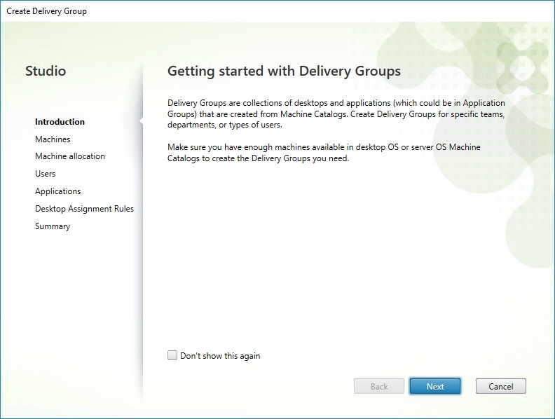
Step 3. Click Next.
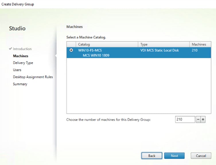
Step 4. Specify the Machine Catalog and increment the number of machines to add.
Step 5. Click Next.
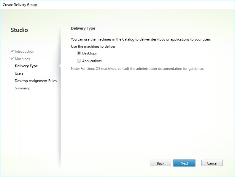
Step 6. Specify what the machines in the catalog will deliver: Desktops, Desktops and Applications, or Applications.
Step 7. Select Desktops.
Step 8. Click Next.
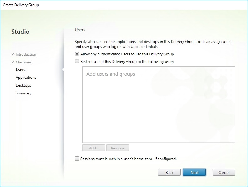
Step 9. You must add users to make the Delivery Group accessible. Select Allow any authenticated users to use this Delivery Group.
Note: User assignment can be updated any time after Delivery group creation by accessing Delivery group properties in Desktop Studio.
Step 10. Click Next.
Step 11. Click Next (no applications are used in this design).
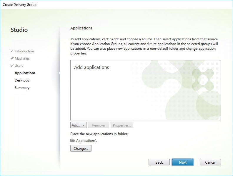
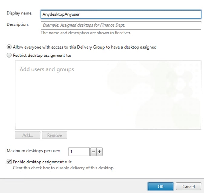
Step 12. Enable Users to access the desktops.
Step 13. Click Next.
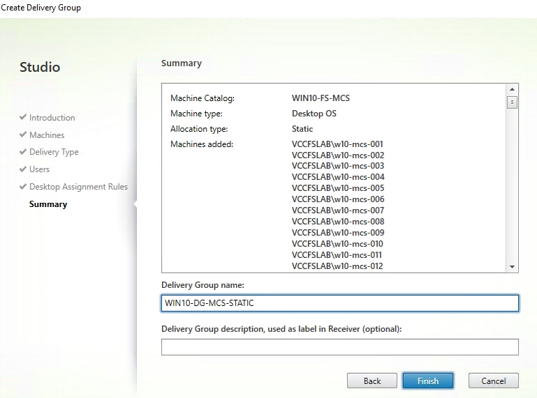
Step 14. On the Summary dialog, review the configuration. Enter a Delivery Group name and a Description (Optional).
Step 15. Click Finish.
Citrix Studio lists the created Delivery Groups as well as the type, number of machines created, sessions, and applications for each group in the Delivery Groups tab.
Step 16. From the drop-down list, select Turn on Maintenance Mode.
Citrix Virtual Apps and Desktops Policies and Profile Management
Policies and profiles allow the Citrix Virtual Apps and Desktops environment to be easily and efficiently customized.
Configure Citrix Virtual Apps and Desktops Policies
Citrix Virtual Apps and Desktops policies control user access and session environments, and are the most efficient method of controlling connection, security, and bandwidth settings. You can create policies for specific groups of users, devices, or connection types with each policy. Policies can contain multiple settings and are typically defined through Citrix Studio. The policy used in testing was generated from the Higher Server Scalability Template with the additional setting shown in Table7.
The Windows Group Policy Management Console can also be used if the network environment includes Microsoft Active Directory and permissions are set for managing Group Policy Objects.
Figure 8 shows the policies for Login VSI testing in this CVD.
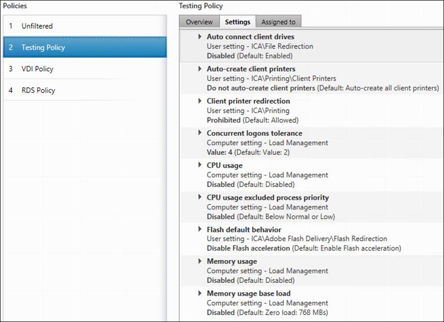
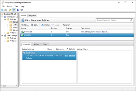
Table 6. Additional testing policy settings
| Setting |
Value |
| HX Adaptive Transport |
Off |
| Client Fixed Drives |
Prohibited |
| Client Optical Drives |
Prohibited |
| Client Network Drives |
Prohibited |
| Client Removable Drives |
Prohibited |
| Use Video Codec for compression |
Do not use video codec |
| View window contents while dragging |
Prohibited |
| Windows Media fallback prevention |
Play all content |
This chapter contains the following:
● Test Methodology and Success Criteria
Test Methodology and Success Criteria
All validation testing was conducted on-site within the Cisco labs in San Jose, California.
The testing results focused on the entire virtual desktop lifecycle by capturing metrics during desktop boot-up, user logon and virtual desktop acquisition (also referred to as ramp-up), user workload execution (also referred to as steady state), and user logoff for the RDSH/VDI Session under test.
Test metrics were gathered from the virtual desktop, storage, and load generation software to assess the overall success of an individual test cycle. Each test cycle was not considered passing unless all the planned test users completed the ramp-up and steady-state phases (described below) and unless all metrics were within the permissible thresholds as noted as success criteria.
Three successfully completed test cycles were conducted for each hardware configuration, and results were relatively consistent from one test to the next.
You can obtain additional information and a free test license from http://www.loginvsi.com
Pre-Test Setup for Single and Multi-Blade Testing
All virtual machines were shut down utilizing the Citrix Studio.
All Launchers for the test were shut down. They were then restarted in groups of 10 each minute until the required number of launchers were running with the Login Enterprise UI started and registered with Login Enterprise Virtual Appliance.
To simulate real-world environments, Cisco requires the log-on and start-work sequence, known as Ramp Up, to be completed in 48 minutes. For testing, we deem the test run successful with up to 1% session failure rate.
In addition, Cisco performs three consecutive load tests with knowledge worker workload for all single server and scale testing. This assures that our tests represent real-world scenarios. For each of the three consecutive runs on single server tests, the same process was followed.
To do so, follow these steps:
1. Time 0:00:00 Start Performance Logging on the following system:
a. Prism Element used in the test run.
2. All Infrastructure virtual machines used in test run (AD, SQL, brokers, image mgmt., and so on)
3. Time 0:00:10 Start Storage Partner Performance Logging on Storage System if used in the test.
4. Time 0:05: Boot Virtual Desktops/RDS Virtual Machines using Citrix Studio.
5. The boot rate should be around 10-12 virtual machines per minute per server.
6. Time 0:06 First machines boot.
7. Time 0:30 Single Server or Scale target number of desktop virtual machines booted on 1 or more blades.
8. No more than 30 minutes for boot up of all virtual desktops is allowed.
9. Time 0:35 Single Server or Scale target number of desktop virtual machines desktops registered in Citrix Studio.
10. Virtual machine settling time.
11. No more than 60 Minutes of rest time is allowed after the last desktop is registered on the Citrix Studio. Typically, a 30-45-minute rest period is sufficient.
12. Time 1:35 Start Login Enterprise Load Test, with Single Server or Scale target number of desktop virtual machines utilizing a sufficient number of Launchers (at 20-25 sessions/Launcher).
13. Time 2:23 Single Server or Scale target number of desktop virtual machines desktops launched (48 minute benchmark launch rate).
14. Time 2:25 All launched sessions must become active.
15. Time 2:40 Login Enterprise Load Test Ends (based on Auto Logoff 15 minutes period designated above).
16. Time 2:55 All active sessions logged off.
17. Time 2:57 All logging terminated; Test complete.
18. Time 3:15 Copy all log files off to archive; Set virtual desktops to maintenance mode through broker; Shutdown all Windows machines.
19. Time 3:30 Reboot all hypervisor hosts.
20. Time 3:45 Ready for the new test sequence.
Our pass criteria for this testing is as follows:
● Cisco will run tests at a session count level that effectively utilizes the blade capacity measured by CPU utilization, memory utilization, storage utilization, and network utilization. We will use Login Enterprise to launch Knowledge Worker workloads. The number of launched sessions must equal active sessions within two minutes of the last session launched in a test as observed on the Login Enterprise Web Management console.
The Citrix Studio will be monitored throughout the steady state to make sure of the following:
● All running sessions report In Use throughout the steady state
● No sessions move to unregistered, unavailable, or available state at any time during steady state
● Within 20 minutes of the end of the test, all sessions on all launchers must have logged out automatically.
● Cisco requires three consecutive runs with results within +/-1% variability to pass the Cisco Validated Design performance criteria.
We will publish Cisco Validated Designs with our recommended workload following the process above and will note that we did not reach a VSImax dynamic in our testing. Cisco Compute Hyperconverged with Nutanix in Intersight Standalone Mode and Citrix Virtual Apps and Desktops 2203 LTSR Test Results.
The purpose of this testing is to provide the data needed to validate CVAD Remote Desktop Sessions (RDS) and CVAD Virtual Desktop (VDI) PVS streamed and CVAD (VDI) MCS provisioned full-clones using CCH with Nutanix in ISM to virtualize Microsoft Windows 11 desktops and Microsoft Windows Server 2022 sessions on Cisco UCS HCIAF240C M7 Servers.
The information contained in this section provides data points that a customer may reference in designing their own implementations. These validation results are an example of what is possible under the specific environment conditions outlined here, and do not represent the full characterization of Cisco and Citrix products.
Four test sequences, each containing three consecutive test runs generating the same result, were performed to establish single blade performance and multi-blade, linear scalability.
Login VSI helps organizations proactively manage the performance, cost, and capacity of their virtual desktops and applications wherever they reside – traditional, hybrid, or in the cloud. The Login Enterprise platform is 100% agentless and can be used in all major VDI and DaaS environments, including Citrix, VMware, and Microsoft. With 360° proactive visibility, IT teams can plan and maintain successful digital workplaces with less cost, fewer disruptions, and lower risk. Founded in 2012, Login VSI is headquartered in Boston, Massachusetts, and Amsterdam, Netherlands. Visit www.loginvsi.com.
Login Enterprise, by Login VSI, is the industry-standard software used to simulate a human-centric workload used for the purpose of benchmarking the capacity and performance of a VDI solutions. The performance testing documented in this Reference Architecture utilized the Login Enterprise benchmarking tool (https://www.loginvsi.com/platform/). The virtual user technology of Login Enterprise simulates real-world users performing real-world tasks while measuring the time required for each interaction. Login Enterprise assesses desktop performance, application performance, and user experience to determine the overall responsiveness of the VDI solution. Using Login Enterprise for VDI capacity planning helps to determine the optimal hardware configuration to support the desired number of users and applications.
About the EUX Score
The Login Enterprise End-User Experience (EUX) Score is a unique measurement that provides an accurate and realistic evaluation of user experience in virtualized or physical desktop environments. The score is based on metrics that represent system resource utilization and application responsiveness. The results are then combined to produce an overall score between 1 and 10 that closely correlates with the real user experience. See the table below for general performance guidelines with respect to the EUX Score.
| Score |
Assessment |
| Greater than 8.5 |
Excellent |
| 7.5-8.5 |
Very Good |
| 6.5 – 7.5 |
Good |
| 5.5 – 6.5 |
Fair |
| Less than 5.5 |
Poor |
See the following article for more information: https://support.loginvsi.com/hc/en-us/articles/4408717958162-Login-Enterprise-EUX-Score-
About VSImax
The Login Enterprise VSImax is a performance metric used to measure the maximum user capacity or scalability of a virtualized desktop infrastructure (VDI) environment. The EUX Score is used to determine the VSImax, and it represents the maximum number of virtual users that can be supported by the infrastructure while still maintaining acceptable performance levels.
Login Enterprise Workloads
Login Enterprise Workloads are human-centric workloads designed to simulate a user interacting with predetermined applications in a human-paced way. The industry-standard workloads that come with Login Enterprise are Knowledge Worker and Task Worker. These workloads are based on the Microsoft Office suite and popular browsers used in the enterprise. Other workloads are available from Login VSI.
Knowledge worker
An enterprise knowledge worker is a medium to heavy duty productivity user that regularly uses a web browser, an email client, and specializes in a wide range of software to create spreadsheets, documents, and presentations. It is common for knowledge workers to have multiple applications and browsers open at once, regularly switching between these applications. The knowledge worker expects a responsive user experience and has little tolerance for variation in performance.
Task worker
An enterprise task worker is a light duty productivity user that regularly uses a static web browser to access internal sites, an email client and an application that is the basis for their task. Task workers stay focused on the task at hand and switch between apps on occasion. The task worker is tolerant of some workspace lag. Task workers often take the form of data processing workers, call center agents, tellers, and receptionists.
Test Setup, Configuration, and Load Recommendation
This chapter contains the following:
● Cisco UCS Test Configuration for Single Blade Scalability
● Cisco UCS Test Configuration for Full Scale Testing
We tested a single Cisco UCS HCIAF240C M7 server and four Cisco UCS HCIAF240C M7 servers in a four-node cluster to illustrate linear scalability for each workload use case studied.
Cisco UCS Test Configuration for Single Blade Scalability
This test case validates the Recommended Maximum Workload per host server using Citrix Virtual Apps and Desktops 2203 LTSR with 224 Multi-session and 200 Single-session OS sessions.
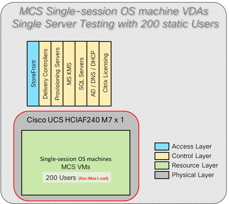
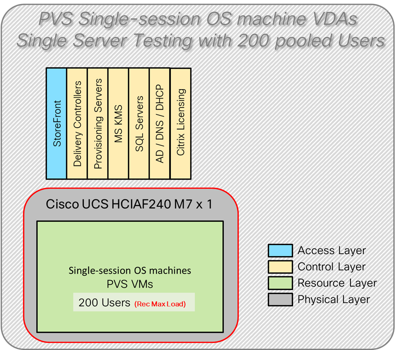
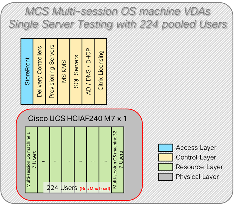
● 1 Cisco UCS HCIAF240C M7 All-NVMe/All-Flash Server with Intel(R) Xeon(R) Gold I6454S CPU 2.2GHz 32-core processors, 1TB 4800MHz RAM, 6 3.8TB 2.5 NVMe High Perf Medium Endurance for all cluster servers
● 2 Cisco Nexus 93180YC-FX Access Switches
Software component:
● Cisco UCS C-Series 4.3(3.240043)
● AOS 6.8.0.1
● AHV 20230302.100187 for host blades
● Prism Central 2024.1.0.1
● Nutanix AHV Plugin 2.7.7
● Citrix Virtual Apps and Desktops 2203 LTSR
● Microsoft SQL Server 2019
● Microsoft Windows 11 64 bit (22H2), 2vCPU, 4 GB RAM, 64 GB HDD (master)
● Microsoft Windows Server 2022 (21H2), 4vCPU, 24GB RAM, 90 GB vDisk (master)
● Microsoft Office 2021 64-bit
● FSLogix 2210 hotfix 3
● Login Enterprise 5.11.12 Knowledge Worker Workload
Cisco UCS Test Configuration for Full Scale Testing
These test cases validate eight blades in a cluster hosting three distinct workloads using Citrix Virtual Apps and Desktops 2203 LTSR with:
● 600 MCS Single-session OS sessions
● 600 PVS Single-session OS sessions
● 672 MSC Multi-session OS sessions
Note: Server N+1 fault tolerance is factored into this solution for the cluster/workload.
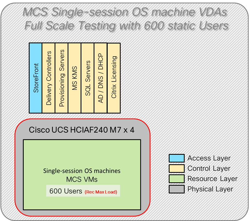
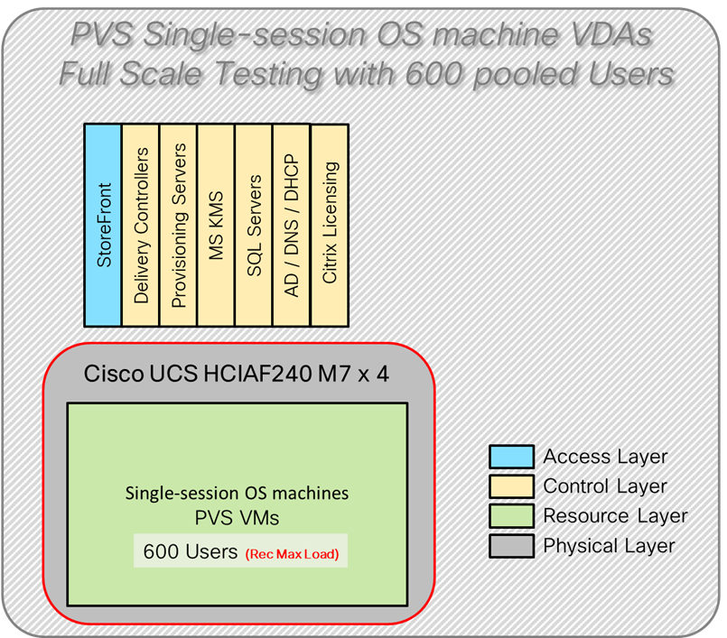
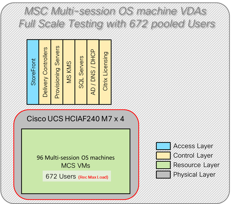
● 4 Cisco UCS HCIAF240C M7 All-NVMe/All-Flash Server with Intel(R) Xeon(R) Gold I6454S CPU 2.2GHz 32-core processors, 1TB 4800MHz RAM, 6 3.8TB 2.5 NVMe High Perf Medium Endurance for all cluster servers
● 2 Cisco Nexus9000 C93180YC-FX Access Switches
Software components
● Cisco UCS C-Series 4.3(3.240043)
● AOS 6.8.0.1
● AHV 20230302.100187 for host blades
● Prism Central 2024.1.0.1
● Nutanix AHV Plugin 2.7.7
● Citrix Virtual Apps and Desktops 2203 LTSR
● Microsoft SQL Server 2019
● Microsoft Windows 11 64 bit (22H2), 2vCPU, 4 GB RAM, 64 GB HDD (master)
● Microsoft Windows Server 2022 (21H2), 4vCPU, 24GB RAM, 90 GB vDisk (master)
● Microsoft Office 2021 64-bit
● FSLogix 2210 hotfix 3
● Login Enterprise 5.11.12 Knowledge Worker Workload
Test Results
This chapter contains the following:
● Single-Server Recommended Maximum Workload Testing
Single-Server Recommended Maximum Workload Testing
This section shows the key performance metrics that were captured on the Cisco UCS host blades during the single server testing to determine the Recommended Maximum Workload per host server. The single server testing comprised of following tests:
● 200 MCS Single-session OS sessions (Static)
● 200 PVS Single-session OS sessions (Random)
● 224 MCS Multi-session OS sessions (Random)
Single-Server Recommended Maximum Workload for MCS Single-session OS Static Sessions with 200 Users
The recommended maximum workload for a Cisco UCS HCIAF240C M7 server with dual Intel(R) Xeon(R) Gold I6454S CPU 2.2GHz 32-core processors, 1TB 4800MHz RAM is 200 Windows 11 64-bit persistent MCS virtual machines with 2 vCPU and 4 GB RAM.
Login VSI performance data is shown below.
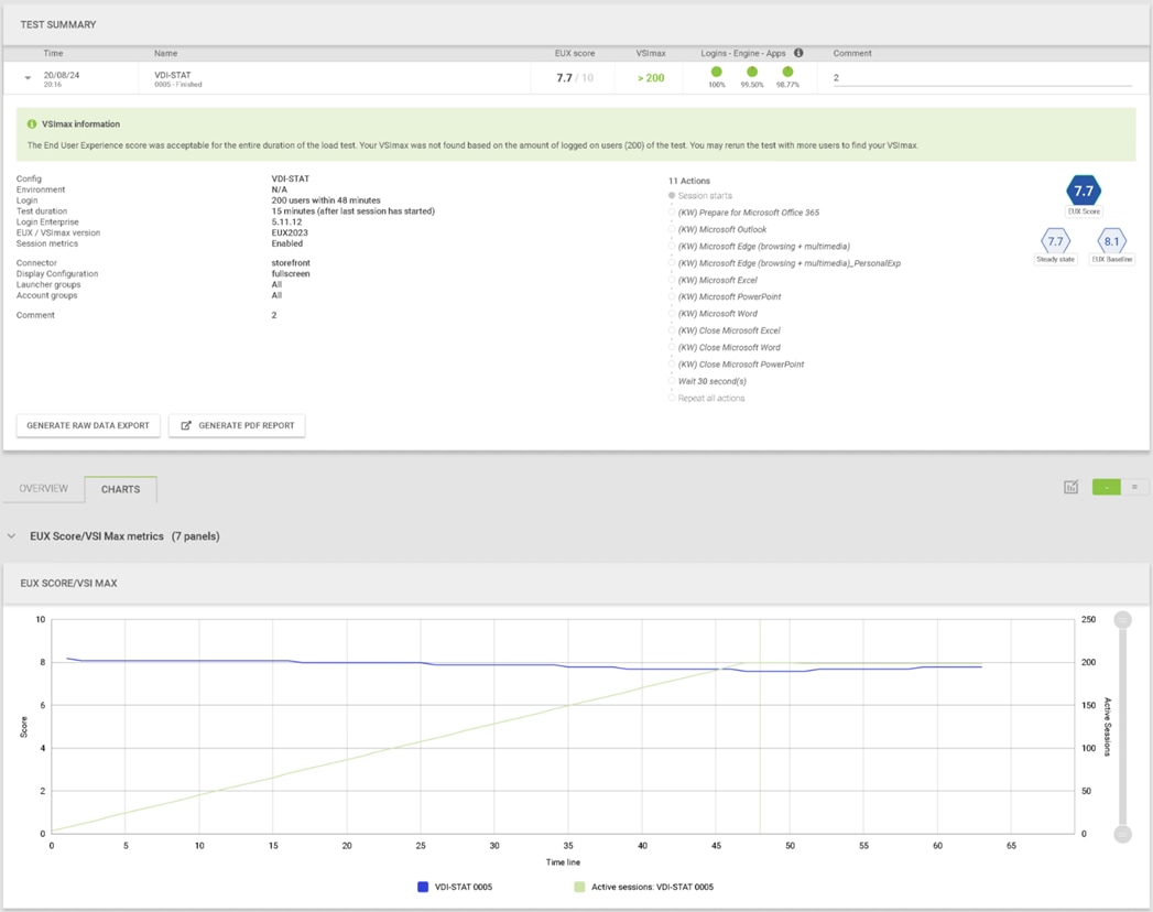
Performance data for the server running the workload is shown below.
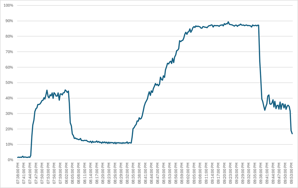
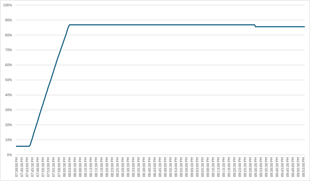
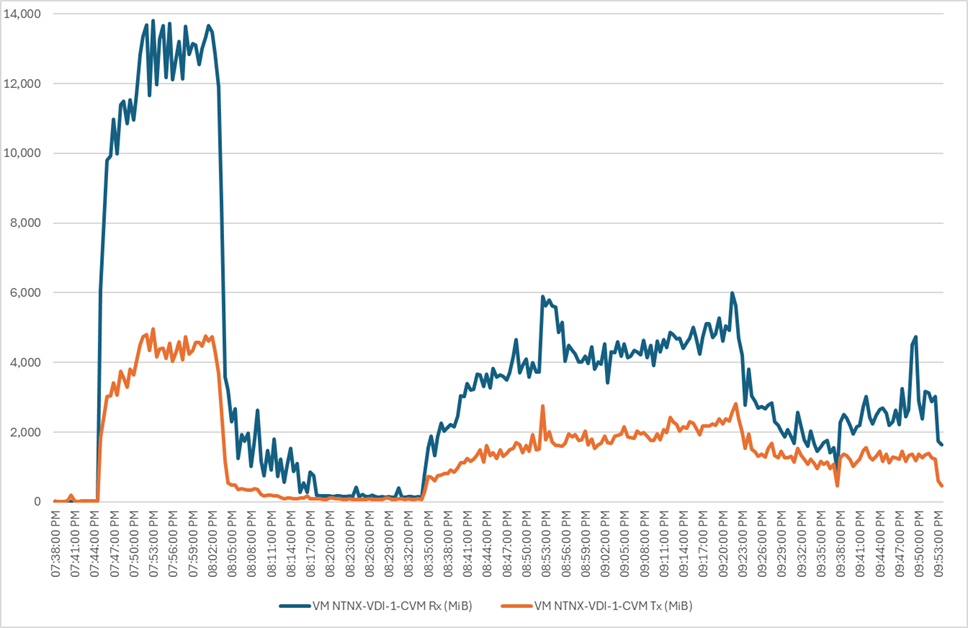
Single-Server Recommended Maximum Workload for PVS Single-session OS Random Sessions with 200 Users
The recommended maximum workload for a Cisco UCS HCIAF240C M7 server with dual Intel(R) Xeon(R) Gold I6454S CPU 2.2GHz 32-core processors, 1TB 4800MHz RAM is 200 Windows 11 64-bit VDI non-persistent PVS virtual machines with 2 vCPU and 4GB RAM.
Login VSI performance data is as shown below.
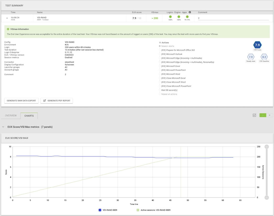
Performance data for the server running the workload is shown below.
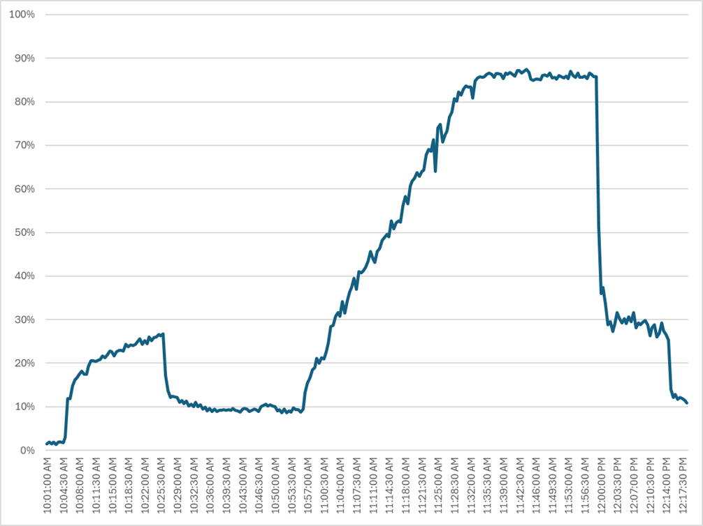
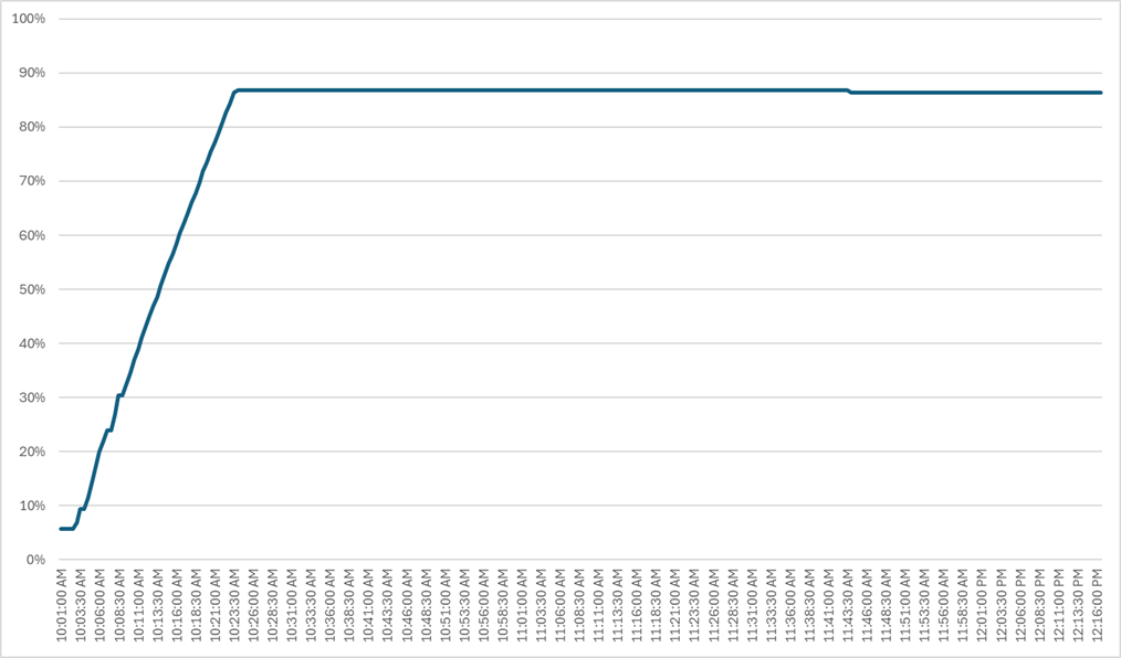
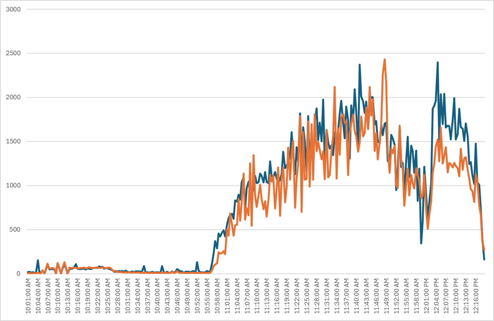
Single-Server Recommended Maximum Workload for MCS Multiple-session OS Random Sessions with 224 Users
The recommended maximum workload for a Cisco UCS HCIAF240C M7 server with dual Intel(R) Xeon(R) Gold I6454S CPU 2.2GHz 32-core processors, 1TB 4800MHz RAM is 224 Windows Server 2022 sessions. The blade server ran 32 Windows Server 2022 Virtual Machines. Each virtual server was configured with 4 vCPUs and 24GB RAM.
LoginVSI data is shown below.
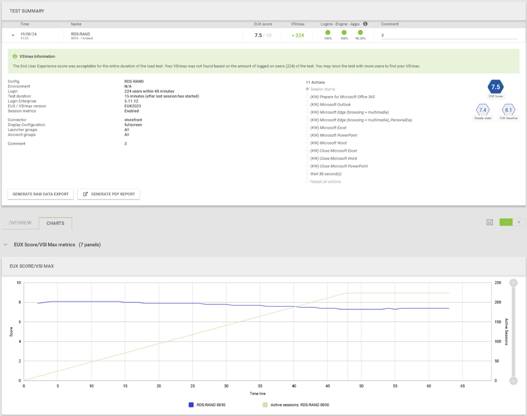
Performance data for the server running the workload is shown below.
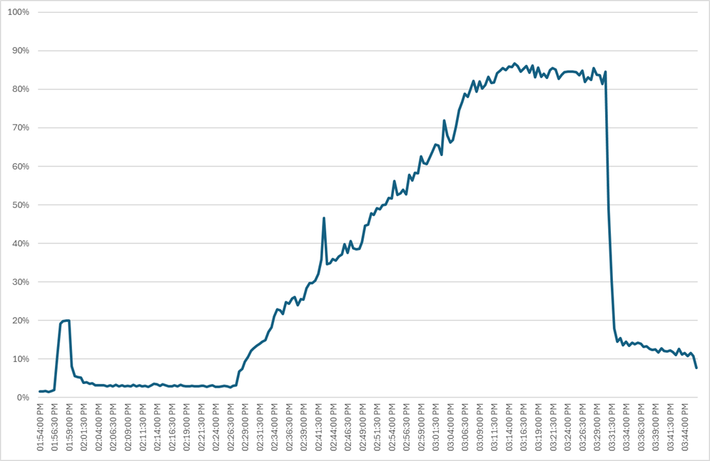
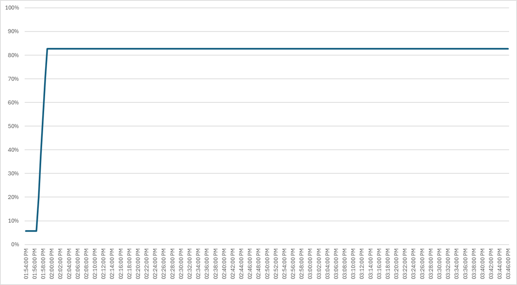
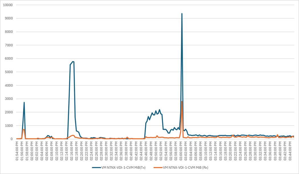
Performance data for the RDS Virtual Machine running the workload is shown below.
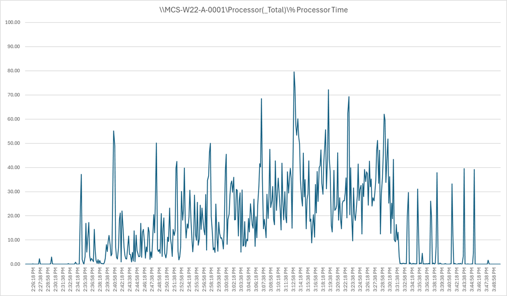
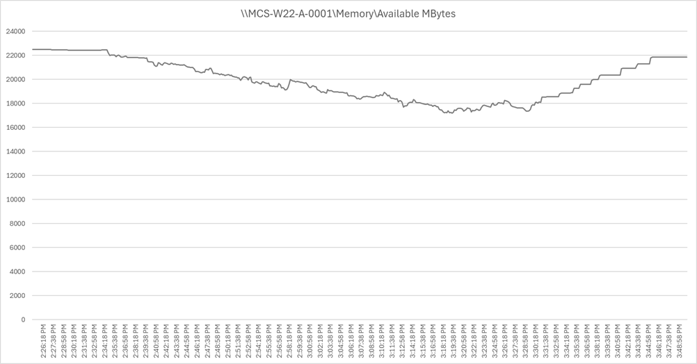
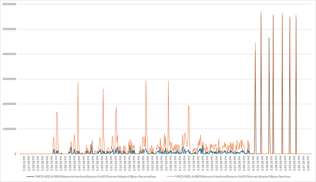
This section describes the key performance metrics that were captured on the Cisco UCS, during the full-scale testing. Full Scale testing was done with following Workloads using four Cisco UCS HCIAF240C M7 Servers configured in a single four-server cluster, and designed to support single Host failure (N+1 Fault tolerance):
● 600 MCS Single-session OS sessions (Static)
● 600 PVS Single-session OS sessions (Random)
● 672 MCS Multi-session OS sessions (Random
To achieve the target, sessions were launched against each workload set. As per the Cisco Test Protocol for VDI solutions, all sessions were launched within 48 minutes (using the official Knowledge Worker Workload), and all launched sessions became active within two minutes after the last logged-in session.
Full Scale Recommended Maximum Workload Testing for MCS Single-session OS Machine VDAs with 600 Users
This section describes the key performance metrics captured on the Cisco UCS during the full-scale testing with 600 MCS Single-session OS machines using four servers in a single cluster.
The workload for the test is 600 Persistent VDI users. To achieve the target, sessions were launched concurrently against all workload hosts. As per the Cisco Test Protocol for VDI solutions, all sessions were launched within 48 minutes (using the official Knowledge Worker Workload) and all launched sessions became active within two minutes subsequent to the last logged-in session.
The configured system efficiently and effectively delivered the following results:
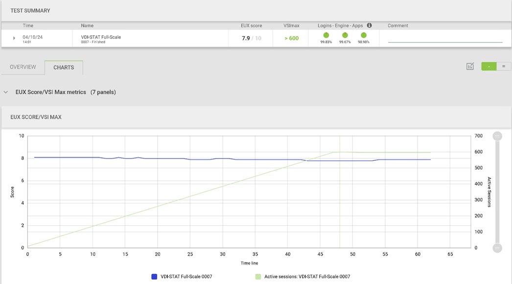
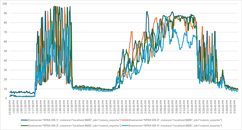
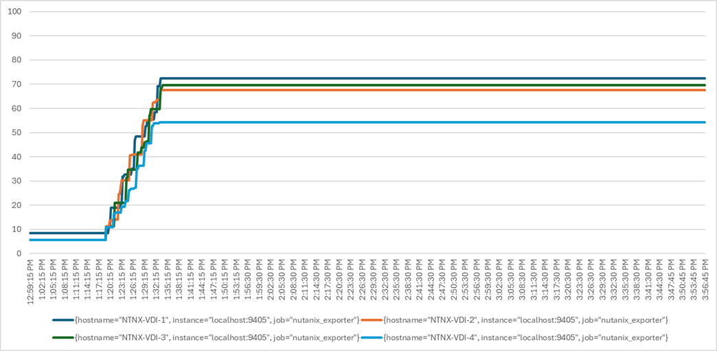
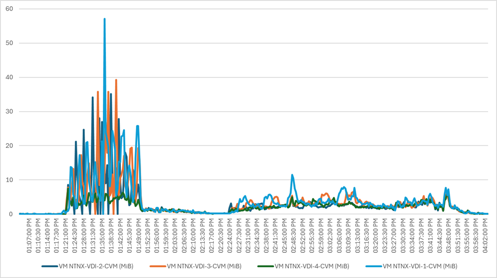
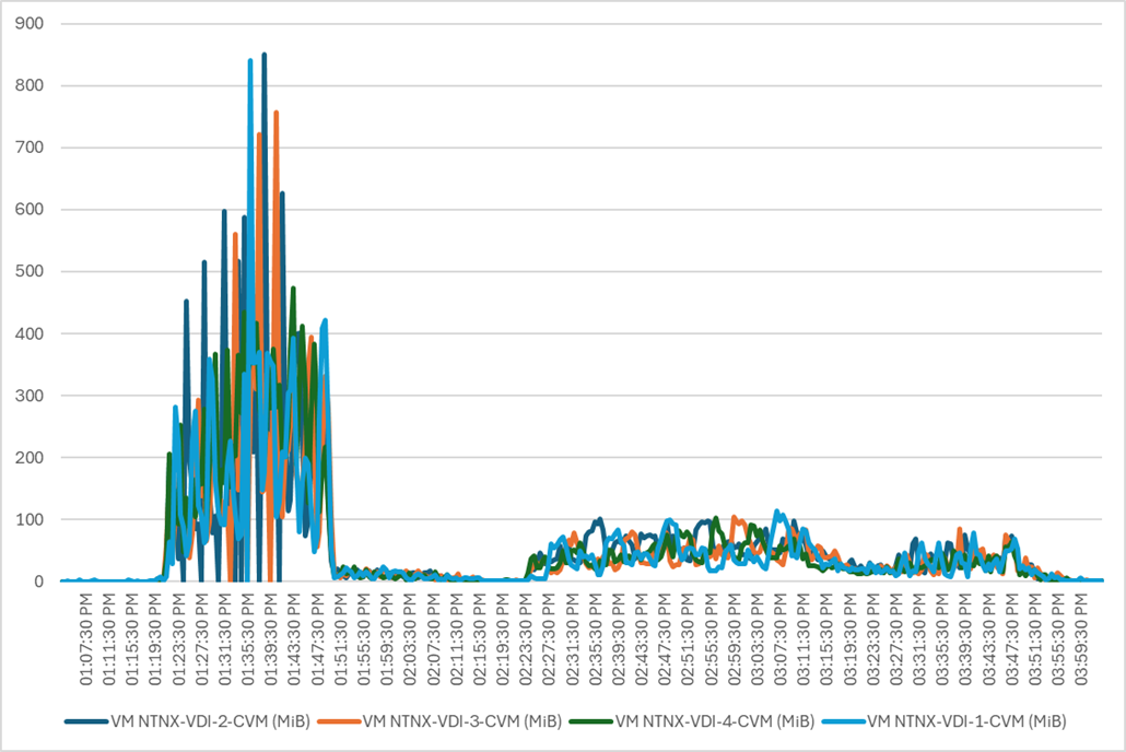
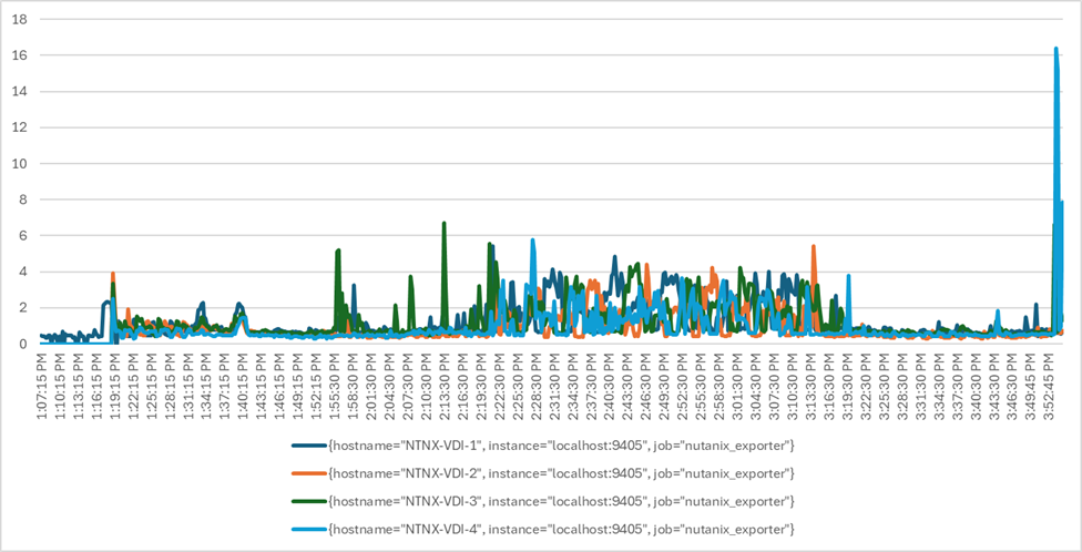
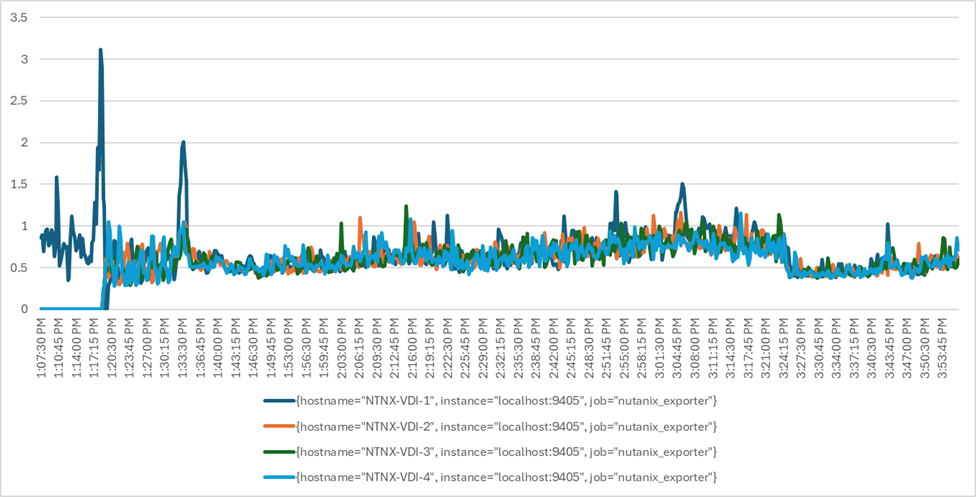
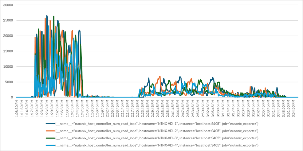
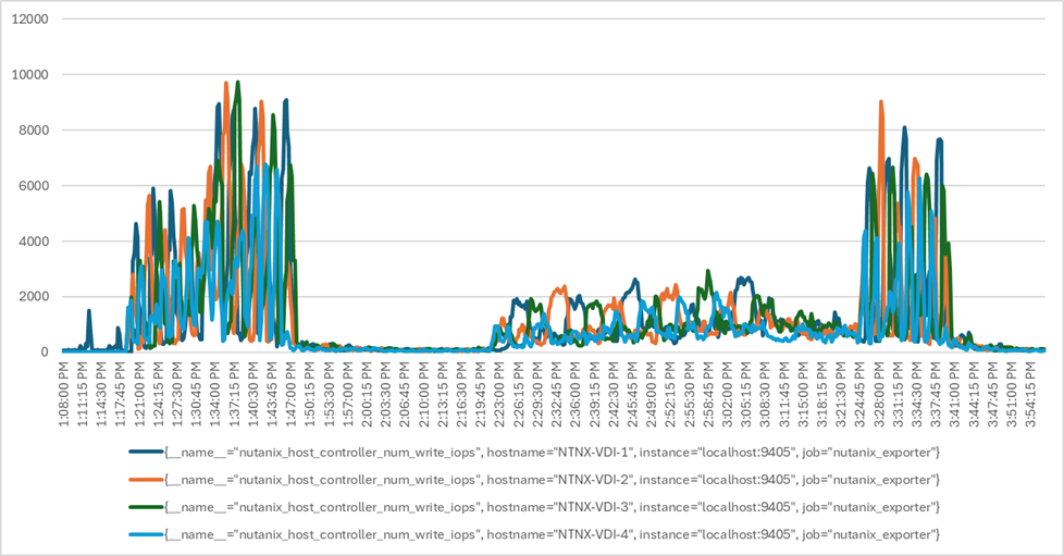
Full Scale Recommended Maximum Workload Testing for PVS Single-session OS Machine VDAs with 600 Users
This section describes the key performance metrics that were captured on the Cisco UCS using the persistent desktop full-scale testing with 600 PVS Single-session OS machines using four servers in a single cluster.
The workload for the test is 600 Non-Persistent VDI users. To achieve the target, sessions were launched concurrently against all workload clusters. As per the Cisco Test Protocol for VDI solutions, all sessions were launched within 48 minutes (using the official Knowledge Worker Workload in VSI Benchmark Mode), and all launched sessions became active within two minutes after the last logged-in session.
The configured system efficiently and effectively delivered the following results:
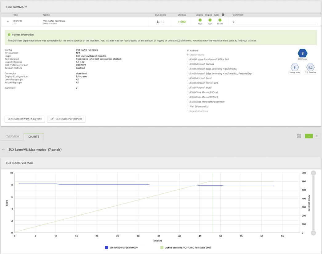
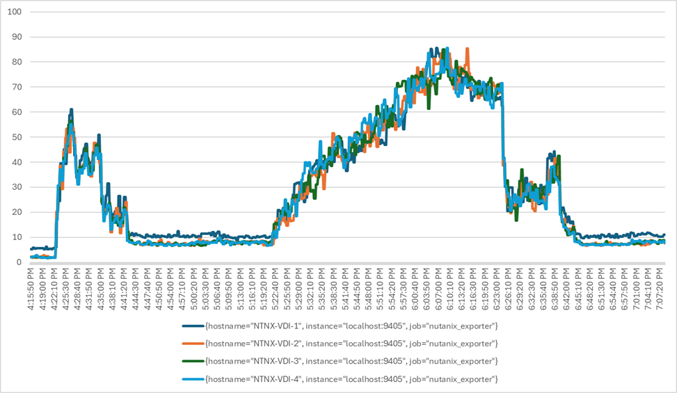
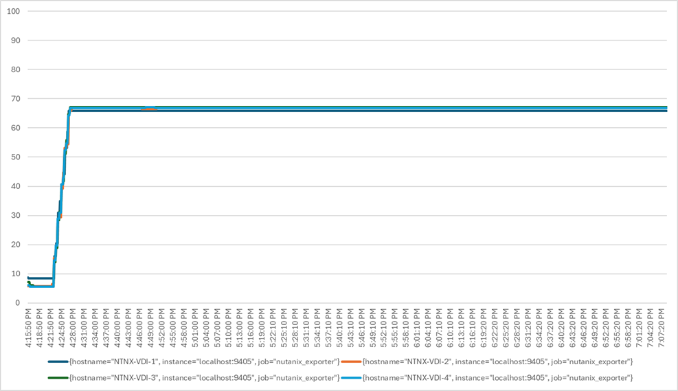
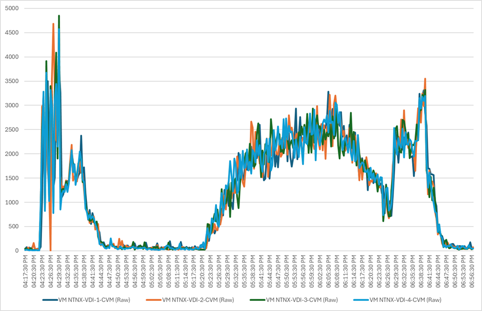
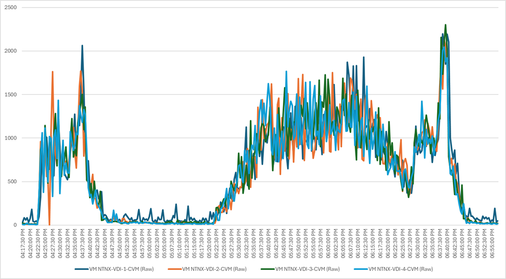
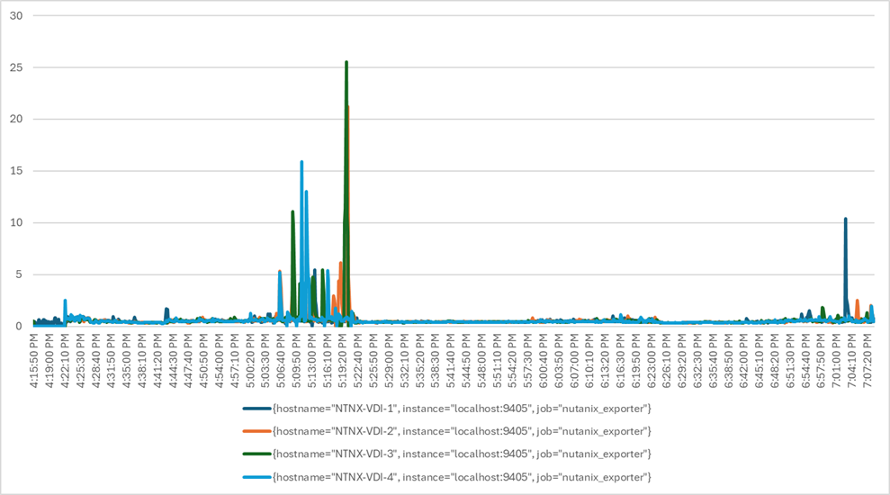
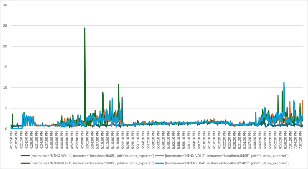
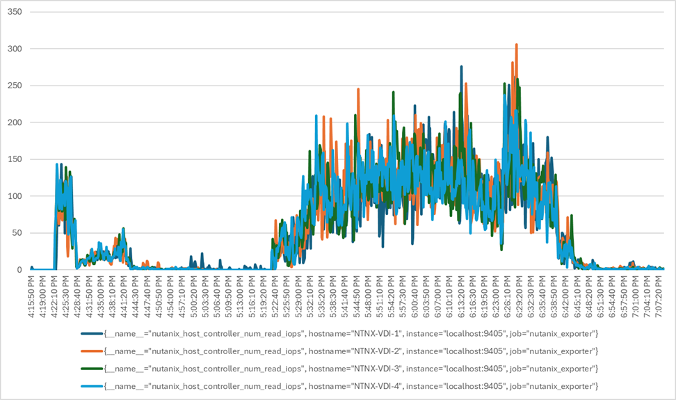
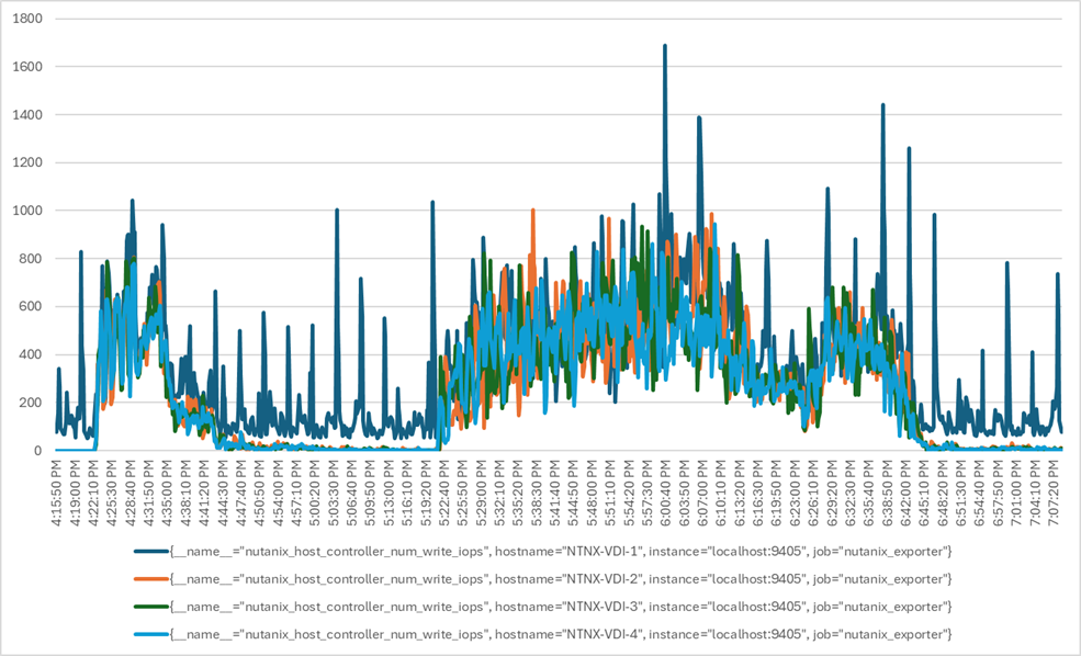
Full Scale Recommended Maximum Workload for MCS Multi-session OS Random Sessions with 672 Users
This section describes the key performance metrics captured on the Cisco UCS during the MCS multi-session OS full-scale testing with 672 desktop sessions using four servers in a single cluster.
The solution’s multi-session OS workload is 672 users. To achieve the target, sessions were launched against all workload clusters concurrently. As per the Cisco Test Protocol for VDI solutions, all sessions were launched within 48 minutes (using the official Knowledge Worker Workload), and all launched sessions became active within two minutes after the last logged-in session.
The configured system efficiently and effectively delivered the following results:
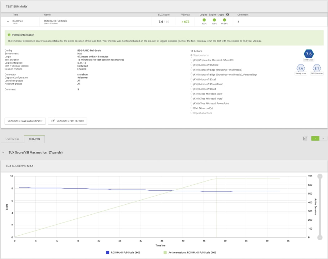

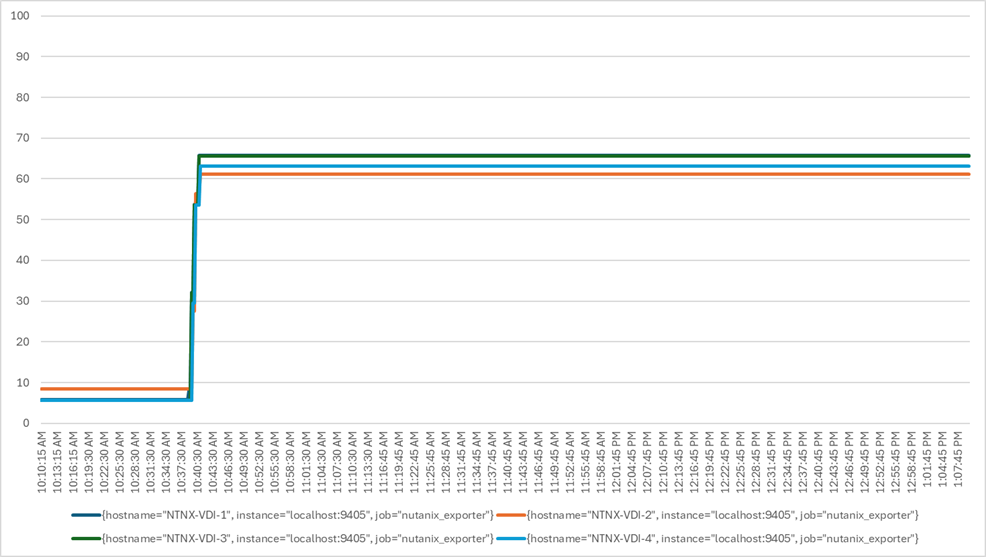
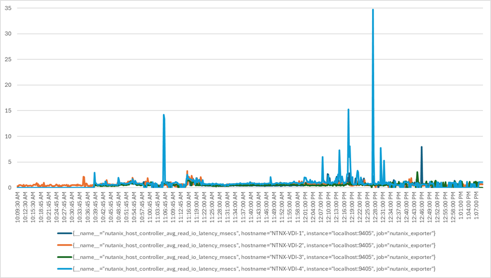
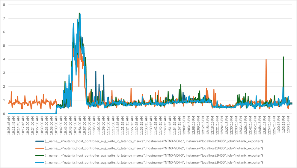
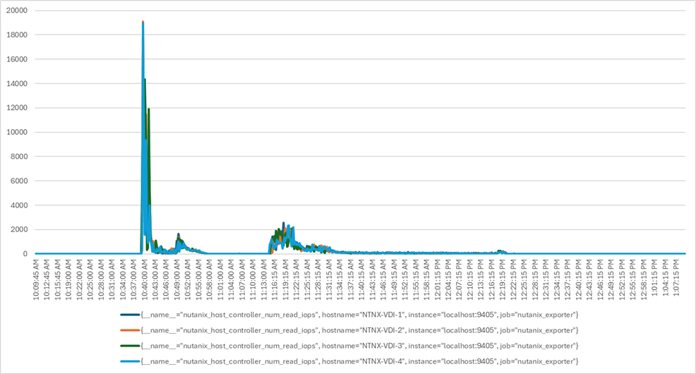
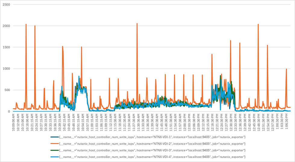
Compute Hyperconverged with Nutanix in Intersight Standalone Mode, offers a reliable and robust solution for enterprise end-user computing deployments. This hyper-converged infrastructure provides compute density, storage capacity, and expandability in a single system to support a wide range of workloads in your data center.
Cisco Intersight makes it easy to deploy the Cisco Compute Hyperconverged with Nutanix in Intersight Standalone Mode. It simplifies the deployment process, reduces project risk and IT costs, as well as enhances visibility and orchestration across the entire data center, allowing you to modernize your infrastructure and operations.
Compute Hyperconverged with Nutanix in Intersight Standalone Mode on Cisco Compute Hyperconverged HCIAF240C M7 Servers with 4th Gen Xeon processors has undergone validation using industry-standard benchmarks, ensuring it meets the highest performance, management, scalability, and resilience standards. It makes an ideal choice for customers seeking enterprise-class hyper-converged infrastructure for virtual desktop infrastructure (VDI) deployments and allows you to focus on your core business objectives.
Vadim Lebedev, Technical Marketing Engineer, Desktop Virtualization and Graphics Solutions, Cisco Systems, Inc.
Vadim Lebedev has been a part of Cisco's Computing Systems Product Group team for the last seven years, where he focuses on designing, testing validating solutions, creating technical content, and conducting performance testing and benchmarking. He has extensive experience in server and desktop virtualization and is considered an expert in desktop/server virtualization, Cisco Unified Computing System, Cisco Nexus Switching, and NVIDIA Graphics.
This appendix contains the following:
● Appendix A - References used in this guide
● Appendix B – Bill of Materials
Appendix A – References used in this guide
Windows 11 on Nutanix AHV: https://portal.nutanix.com/page/documents/solutions/details?targetId=TN-2164-Windows-11-on-AHV:TN-2164-Windows-11-on-AHV
AHV Plug-in for Citrix: https://portal.nutanix.com/page/documents/details?targetId=NTNX-AHV-Plugin-Citrix:NTNX-AHV-Plugin-Citrix
Citrix Virtual Apps and Desktops on G8: Windows 11 Desktops: https://portal.nutanix.com/page/documents/solutions/details?targetId=RA-2111-Citrix-Virtual-Apps-and-Desktops-G8-Windows-11:RA-2111-Citrix-Virtual-Apps-and-Desktops-G8-Windows-11
Appendix B – Bill of Materials
| Part Number |
Description |
Qty |
| HCIAF240C-M7SN |
Cisco Compute Hyperconverged HCIAF240cM7 All Flash NVMe Node |
4 |
| HCI-IS-MANAGED |
Deployment mode for Standalone Server Managed by Intersight |
4 |
| HCI-NVME4-3840 |
3.8TB 2.5in U.2 15mm P5520 Hg Perf Med End NVMe |
24 |
| HCI-M2-240G |
240GB M.2 SATA Micron G2 SSD |
8 |
| HCI-M2-HWRAID |
Cisco Boot optimized M.2 Raid controller |
4 |
| HCI-RAIL-M7 |
Ball Bearing Rail Kit for C220 & C240 M7 rack servers |
4 |
| HCI-TPM-002C |
TPM 2.0, TCG, FIPS140-2, CC EAL4+ Certified, for servers |
4 |
| HCI-AOSAHV-68-SWK9 |
HCI AOS AHV 6.8 SW |
4 |
| UCSC-HSHP-C240M7 |
UCS C240 M7 Heatsink |
8 |
| UCSC-BBLKD-M7 |
UCS C-Series M7 SFF drive blanking panel |
72 |
| UCS-DDR5-BLK |
UCS DDR5 DIMM Blanks |
64 |
| UCSC-M2EXT-240-D |
C240M7 2U M.2 Extender board |
4 |
| UCSC-FBRS2-C240-D |
C240 M7/M8 2U Riser2 Filler Blank |
4 |
| UCSC-FBRS3-C240-D |
C240 M7/M8 2U Riser3 Filler Blank |
4 |
| HCI-CPU-I6454S |
Intel I6454S 2.2GHz/270W 32C/60MB DDR5 4800MT/s |
8 |
| HCI-MRX64G2RE1 |
64GB DDR5-4800 RDIMM 2Rx4 (16Gb) |
64 |
| HCI-MLOM |
Cisco VIC Connectivity |
4 |
| HCI-M-V5D200GV2 |
Cisco VIC 15237 2x 40/100/200G mLOM C-Series w/Secure Boot |
4 |
| HCI-RIS1A-24XM7 |
C240 M7 Riser1A; (x8;x16x, x8); StBkt; (CPU1) |
4 |
| HCI-PSU1-1200W |
1200W Titanium power supply for C-Series Servers |
8 |
| NO-POWER-CORD |
ECO friendly green option, no power cable will be shipped |
4 |
| N9K-C93180YC-FX3 |
Nexus 9300 48p 1/10/25G, 6p 40/100G, MACsec,SyncE |
2 |
| MODE-NXOS |
Mode selection between ACI and NXOS |
2 |
| NXK-AF-PE |
Dummy PID for Airflow Selection Port-side Exhaust |
2 |
| NXK-ACC-KIT-1RU |
Nexus 3K/9K Fixed Accessory Kit, 1RU front and rear removal |
2 |
| NXA-FAN-35CFM-PE |
Nexus Fan, 35CFM, port side exhaust airflow |
8 |
| NXK-MEM-16GB |
Additional memory of 16GB for Nexus Switches |
2 |
| NXA-PAC-650W-PE |
Nexus NEBs AC 650W PSU - Port Side Exhaust |
4 |
| CAB-9K12A-NA |
Power Cord, 125VAC 13A NEMA 5-15 Plug, North America |
4 |
| SVS-L1N9KA-XF-3Y |
CX L1 Support:DCN Advantage Term N9300 XF, 3Y |
2 |
| C1A1TN9300XF-3Y |
DCN Advantage Term N9300 XF, 3Y |
2 |
| NXOS-CS-10.3.2F |
Nexus 9300, 9500, 9800 NX-OS SW 10.3.2 (64bit) Cisco Silicon |
2 |
| NXOS-SLP-INFO-9K |
Info PID for Smart Licensing using Policy for N9K |
2 |
| C1-N9K-SYNCE-XF-3Y |
DCN SyncE Term N9300 XF, 3Y |
2 |
| SVS-L1N9K-SYNCE-3Y |
CX L1 Support: DCN SyncE Term N9300 XF, 3Y |
2 |
For comments and suggestions about this guide and related guides, join the discussion on Cisco Community at https://cs.co/en-cvds.
CVD Program
ALL DESIGNS, SPECIFICATIONS, STATEMENTS, INFORMATION, AND RECOMMENDATIONS (COLLECTIVELY, "DESIGNS") IN THIS MANUAL ARE PRESENTED "AS IS," WITH ALL FAULTS. CISCO AND ITS SUPPLIERS DISCLAIM ALL WARRANTIES, INCLUDING, WITHOUT LIMITATION, THE WARRANTY OF MERCHANTABILITY, FITNESS FOR A PARTICULAR PURPOSE AND NONINFRINGEMENT OR ARISING FROM A COURSE OF DEALING, USAGE, OR TRADE PRACTICE. IN NO EVENT SHALL CISCO OR ITS SUPPLIERS BE LIABLE FOR ANY INDIRECT, SPECIAL, CONSEQUENTIAL, OR INCIDENTAL DAMAGES, INCLUDING, WITHOUT LIMITATION, LOST PROFITS OR LOSS OR DAMAGE TO DATA ARISING OUT OF THE USE OR INABILITY TO USE THE DESIGNS, EVEN IF CISCO OR ITS SUPPLIERS HAVE BEEN ADVISED OF THE POSSIBILITY OF SUCH DAMAGES.
THE DESIGNS ARE SUBJECT TO CHANGE WITHOUT NOTICE. USERS ARE SOLELY RESPONSIBLE FOR THEIR APPLICATION OF THE DESIGNS. THE DESIGNS DO NOT CONSTITUTE THE TECHNICAL OR OTHER PROFESSIONAL ADVICE OF CISCO, ITS SUPPLIERS OR PARTNERS. USERS SHOULD CONSULT THEIR OWN TECHNICAL ADVISORS BEFORE IMPLEMENTING THE DESIGNS. RESULTS MAY VARY DEPENDING ON FACTORS NOT TESTED BY CISCO.
CCDE, CCENT, Cisco Eos, Cisco Lumin, Cisco Nexus, Cisco StadiumVision, Cisco TelePresence, Cisco WebEx, the Cisco logo, DCE, and Welcome to the Human Network are trademarks; Changing the Way We Work, Live, Play, and Learn and Cisco Store are service marks; and Access Registrar, Aironet, AsyncOS, Bringing the Meeting To You, Catalyst, CCDA, CCDP, CCIE, CCIP, CCNA, CCNP, CCSP, CCVP, Cisco, the Cisco Certified Internetwork Expert logo, Cisco IOS, Cisco Press, Cisco Systems, Cisco Systems Capital, the Cisco Systems logo, Cisco Unified Computing System (Cisco UCS), Cisco UCS B-Series Blade Servers, Cisco UCS C-Series Rack Servers, Cisco UCS S-Series Storage Servers, Cisco UCS X-Series, Cisco UCS Manager, Cisco UCS Management Software, Cisco Unified Fabric, Cisco Application Centric Infrastructure, Cisco Nexus 9000 Series, Cisco Nexus 7000 Series. Cisco Prime Data Center Network Manager, Cisco NX-OS Software, Cisco MDS Series, Cisco Unity, Collaboration Without Limitation, EtherFast, EtherSwitch, Event Center, Fast Step, Follow Me Browsing, FormShare, GigaDrive, HomeLink, Internet Quotient, IOS, iPhone, iQuick Study, LightStream, Linksys, MediaTone, MeetingPlace, MeetingPlace Chime Sound, MGX, Networkers, Networking Academy, Network Registrar, PCNow, PIX, PowerPanels, ProConnect, ScriptShare, SenderBase, SMARTnet, Spectrum Expert, StackWise, The Fastest Way to Increase Your Internet Quotient, TransPath, WebEx, and the WebEx logo are registered trade-marks of Cisco Systems, Inc. and/or its affiliates in the United States and certain other countries. (LDW_P5)
All other trademarks mentioned in this document or website are the property of their respective owners. The use of the word partner does not imply a partnership relationship between Cisco and any other company. (0809R)
 Feedback