GPU Card Installation

This chapter contains the following topics:

Server Firmware Requirements

The following table lists the minimum server firmware versions for the supported GPU cards.

GPU Card

Cisco IMC/BIOS Minimum Version Required

NVIDIA L4 PCIe, 72W, Gen 4 x8 (UCSC-GPU-L4)

4.1(3)

Intel GPU Flex 140 PCIe, 75W, Gen 4 x8 (UCSC-GPU-FLEX140)

4.1(3)

GPU Card Configuration Rules

Note the following rules when populating a server with GPU cards.

  • The server supports the following GPUs:

    • NVIDIA L4 70W 24GB PCIe GPU (UCSC-GPU-L4), which is a half-height, half-length (HHHL) GPU single-wide GPU card. This GPU can be installed in either PCIe Gen 4 or PCIe Gen 5 half-height or full-height risers.Each server can support a maximum of 3 GPUs of the same type with half-height (HH risers) or a maximum of 2 GPUs of the same type with full-height (FH) risers.

    • Intel GPU Flex 140 Gen4x8 75W PCIe (UCSC-GPU-FLEX140), which is a half-height, half-length (HHHL) GPU single-wide GPU card. This GPU can be installed in either PCIe Gen4 or PCIe Gen5 half-height risers. Each server can support a maximum of 3 GPUs of the same type with half-height (HH risers) or a maximum of 2 GPUs of the same type with full-height (FH) risers.

  • You can install up to three single-wide GPU cards in PCIe slots 1 and 2.

  • You can install a GPU either full-height PCIe riser 1 or 2 (or both).

  • Use the UCS power calculator at the following link to determine the power needed based on your server configuration: http://ucspowercalc.cisco.com

  • You cannot mix GPU cards in the server. Mixing GPUs is not supported.

  • All GPU cards must be procured from Cisco as there is a unique SBIOS ID required by Cisco management tools, such a CIMC and UCSM.

  • To support one or more GPUs, the server must have two CPUs and two full-height rear risers.

Requirement For All GPUs: Memory-Mapped I/O Greater Than 4 GB

All supported GPU cards require enablement of the BIOS setting that allows greater than 4 GB of memory-mapped I/O (MMIO).

  • Standalone Server: If the server is used in standalone mode, this BIOS setting is enabled by default:

    Advanced > PCI Configuration > Memory Mapped I/O Above 4 GB [Enabled]

    If you need to change this setting, enter the BIOS Setup Utility by pressing F2 when prompted during bootup.

  • If the server is integrated with Cisco UCS Manager and is controlled by a service profile, this setting is enabled by default in the service profile when a GPU is present.

    To change this setting manually, use the following procedure.

Procedure


Step 1

Refer to the Cisco UCS Manager configuration guide (GUI or CLI) for your release for instructions on configuring service profiles:

Cisco UCS Manager Configuration Guides

Step 2

Refer to the chapter on Configuring Server-Related Policies > Configuring BIOS Settings.

Step 3

In the section of your profile for PCI Configuration BIOS Settings, set Memory Mapped IO Above 4GB Config to one of the following:

  • Disabled—Does not map 64-bit PCI devices to 64 GB or greater address space.

  • Enabled—Maps I/O of 64-bit PCI devices to 64 GB or greater address space.

  • Platform Default—The policy uses the value for this attribute contained in the BIOS defaults for the server. Use this only if you know that the server BIOS is set to use the default enabled setting for this item.

Step 4

Reboot the server.

Note


Cisco UCS Manager pushes BIOS configuration changes through a BIOS policy or default BIOS settings to the Cisco Integrated Management Controller (CIMC) buffer. These changes remain in the buffer and do not take effect until the server is rebooted.


Replacing a Single-Wide GPU Card

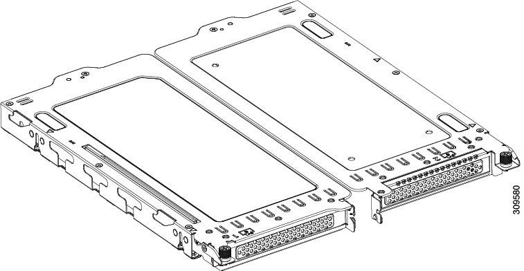
A GPU kit (UCSC-GPURKIT-C220) is available from Cisco. The kit contains a GPU mounting bracket and the following risers (risers 1 and 2):

  • One x16 PCIe Gen4 riser, standard PCIe, supports Cisco VIC, full-height, 3/4 length

  • One x16 PCIe Gen4 riser, standard PCIe, full-height, 3/4 length

Procedure


Step 1

Remove an existing GPU card from the PCIe riser:

  1. Shut down and remove power from the server as described in Shutting Down and Removing Power From the Server.

  2. Slide the server out the front of the rack far enough so that you can remove the top cover. You might have to detach cables from the rear panel to provide clearance.

    Caution

     
    If you cannot safely view and access the component, remove the server from the rack.
  3. Remove the top cover from the server as described in Removing Top Cover.

  4. Using a #2 Phillips screwdriver, loosen the captive screws.

  5. Lift straight up to disengage the riser from the motherboard. Set the riser upside-down on an antistatic surface.

  6. Pull evenly on both ends of the GPU card to disconnect the card from the socket.

    If the riser has no card, remove the blanking panel from the rear opening of the riser.

Step 2

Holding the GPU level, slide it out of the socket on the PCIe riser.

Step 3

Install a new GPU card:

Note


The Intel Flex 140 and Nvidia L4 are half-height, half-length cards. If one is installed in full-height PCIe slot 1, it requires a full-height rear-panel tab installed to the card.

  1. Align the new GPU card with the empty socket on the PCIe riser and slide each end into the retaining clip.

  2. Push evenly on both ends of the card until it is fully seated in the socket.

  3. Ensure that the card’s rear panel tab sits flat against the riser rear-panel opening.

    Figure 1. PCIe Riser Assembly, 3 HHHL

    Note


    For easy identification, riser numbers are stamped into the sheet metal on the top of each riser cage.

    1

    Captive screw for PCIe slot 1 (alignment feature)

    PCIe slot 1 rear-panel opening

    6

    Handle for PCIe slot 3 riser

    2

    Captive screw for PCIe slot 2 (alignment feature)

    7

    Rear-panel opening for PCIe slot 1

    3

    Captive screw for PCIe slot 2 (alignment feature)

    8

    Rear-panel opening for PCIe slot 2

    4

    Handle for PCIe slot 1 riser

    9

    Rear-panel opening for PCIe slot 3

    5

    Handle for PCIe slot 2 riser

    -
    Figure 2. PCIe Riser Assembly, 2 FHFL

    1

    Captive screw for PCIe slot 1

    4

    Handle for PCIe slot 2 riser

    2

    Captive screw for PCIe slot 2

    5

    Rear-panel opening for PCIe slot 1

    3

    Handle for PCIe slot 1 riser

    -

    Rear-panel opening for PCIe slot 2

  4. Position the PCIe riser over its sockets on the motherboard and over the chassis alignment channels.

    Figure 3. PCIe Riser Alignment Features
    • For a server with 3 HHHL risers, 3 sockets and 3 alignment features are available, as shown below.

      1

      Riser alignment features in chassis (captive screws)

      Riser alignment features in chassis (captive screws)

    • For a server with 2 FHFL risers, 2 sockets and 2 alignment features are available, as shown below.

    Figure 4. PCIe Riser Alignment Features

    1

    Riser handles

    2

    Riser alignment features in chassis (captive screws)

  5. Carefully push down on both ends of the PCIe riser to fully engage its two connectors with the two sockets on the motherboard.

  6. When the riser is level and fully seated, use a #2 Phillips screwdriver to secure the riser to the server chassis.

  7. Replace the top cover to the server.

  8. Replace the server in the rack, replace cables, and then fully power on the server by pressing the Power button.

Step 4

Optional: Continue with Installing Drivers to Support the GPU Cards.


Installing Drivers to Support the GPU Cards

After you install the hardware, you must update to the correct level of server BIOS and then install GPU drivers and other software in this order:

  1. Update the server BIOS.

  2. Update the GPU drivers.

1. Updating the Server BIOS

Install the latest Cisco UCS C240 M4 server BIOS by using the Host Upgrade Utility for the Cisco UCS C240 M4 server.


Note


You must do this procedure before you update the NVIDIA drivers.


Procedure


Step 1

Navigate to the following URL: http://www.cisco.com/cisco/software/navigator.html.

Step 2

Click Servers–Unified Computing in the middle column.

Step 3

Click Cisco UCS C-Series Rack-Mount Standalone Server Software in the right-hand column.

Step 4

Click the name of your model of server in the right-hand column.

Step 5

Click Unified Computing System (UCS) Server Firmware.

Step 6

Click the release number.

Step 7

Click Download Now to download the ucs-server platform-huu-version_number.iso file.

Step 8

Verify the information on the next page, and then click Proceed With Download.

Step 9

Continue through the subsequent screens to accept the license agreement and browse to a location where you want to save the file.

Step 10

Use the Host Upgrade Utility to update the server BIOS.

The user guides for the Host Upgrade Utility are at Utility User Guides.


2. Updating the GPU Card Drivers

After you update the server BIOS, you can install GPU drivers to your hypervisor virtual machine.

Procedure


Step 1

Install your hypervisor software on a computer. Refer to your hypervisor documentation for the installation instructions.

Step 2

Create a virtual machine in your hypervisor. Refer to your hypervisor documentation for instructions.

Step 3

Install the GPU drivers to the virtual machine. Download the drivers from either:

Step 4

Restart the server.

Step 5

Check that the virtual machine is able to recognize the GPU card. In Windows, use the Device Manager and look under Display Adapters.