- Preface
- Overview
- Installing the Server OS
- Managing the Server
- Viewing Server Properties
- Viewing Server Sensors
- Managing Remote Presence
- Managing User Accounts
- Configuring Network-Related Settings
- Managing Network Adapters
- Configuring Communication Services
- Managing Certificates
- Configuring Platform Event Filters
- CIMC Firmware Management
- Viewing Faults and Logs
- Server Utilities
- BIOS Parameters by Server Model
- Index
Cisco UCS C-Series Servers Integrated Management Controller GUI Configuration Guide, Release 1.5
Bias-Free Language
The documentation set for this product strives to use bias-free language. For the purposes of this documentation set, bias-free is defined as language that does not imply discrimination based on age, disability, gender, racial identity, ethnic identity, sexual orientation, socioeconomic status, and intersectionality. Exceptions may be present in the documentation due to language that is hardcoded in the user interfaces of the product software, language used based on RFP documentation, or language that is used by a referenced third-party product. Learn more about how Cisco is using Inclusive Language.
- Updated:
- March 4, 2013
Chapter: Managing Network Adapters
- Overview of the Cisco UCS C-Series Network Adapters
- Viewing Network Adapter Properties
- Viewing VIC Adapter Properties
- Viewing Storage Adapter Properties
- Managing vHBAs
- Managing vNICs
- Create Virtual Drive from Unused Physical Drives
- Create Virtual Drive from an Existing Drive Group
- Importing Foreign Configuration
- Clearing Foreign Configuration
- Clearing a Boot Drive
- Enabling JBOD
- Disabling JBOD
- Preparing a Drive for Removal
- Retrieving TTY Logs for a Controller
- Undo Preparing a Drive for Removal
- Making a Dedicated Hot Spare
- Making a Global Hot Spare
- Removing a Drive from Hot Spare Pools
- Toggling Physical Drive Status
- Setting a Physical Drive as a Controller Boot Drive
- Initializing a Virtual Drive
- Set as Boot Drive
- Editing a Virtual Drive
- Deleting a Virtual Drive
- Enabling Auto Learn Cycle for a Battery Backup Unit
- Disabling Auto Learn Cycle for a Battery Backup Unit
- Starting Learn Cycles for a Battery Backup Unit
- Toggling Locator LED for a Physical Drive
- Viewing Storage Controller Logs
Managing Network Adapters
This chapter includes the following sections:
- Overview of the Cisco UCS C-Series Network Adapters
- Viewing Network Adapter Properties
- Viewing VIC Adapter Properties
- Viewing Storage Adapter Properties
- Managing vHBAs
- Managing vNICs
- Managing VM FEX
- Managing Storage Adapters
- Backing Up and Restoring the Adapter Configuration
- Managing Adapter Firmware
- Resetting the Adapter
Overview of the Cisco UCS C-Series Network Adapters
 Note |
The procedures in this chapter are available only when a Cisco UCS C-Series network adapter is installed in the chassis. |
A Cisco UCS C-Series network adapter can be installed to provide options for I/O consolidation and virtualization support. The following adapters are available:
The interactive UCS Hardware and Software Interoperability Utility lets you view the supported components and configurations for a selected server model and software release. The utility is available at the following URL: http://www.cisco.com/web/techdoc/ucs/interoperability/matrix/matrix.html
Cisco UCS P81E Virtual Interface Card
The Cisco UCS P81E Virtual Interface Card is optimized for virtualized environments, for organizations that seek increased mobility in their physical environments, and for data centers that want reduced costs through NIC, HBA, cabling, and switch reduction and reduced management overhead. This Fibre Channel over Ethernet (FCoE) PCIe card offers the following benefits:
- Allows up to 16 virtual Fibre Channel and 16 virtual Ethernet adapters to be provisioned in virtualized or nonvirtualized environments using just-in-time provisioning, providing tremendous system flexibility and allowing consolidation of multiple physical adapters.
- Delivers uncompromising virtualization support, including hardware-based implementation of Cisco VN-Link technology and pass-through switching.
- Improves system security and manageability by providing visibility and portability of network polices and security all the way to the virtual machine.
The virtual interface card makes Cisco VN-Link connections to the parent fabric interconnects, which allows virtual links to connect virtual NICs in virtual machines to virtual interfaces in the interconnect. In a Cisco Unified Computing System environment, virtual links then can be managed, network profiles applied, and interfaces dynamically reprovisioned as virtual machines move between servers in the system.
Cisco UCS VIC1225 Virtual Interface Card
The Cisco UCS VIC1225 Virtual Interface Card is a high-performance, converged network adapter that provides acceleration for the various new operational modes introduced by server virtualization. It brings superior flexibility, performance, and bandwidth to the new generation of Cisco UCS C-Series Rack-Mount Servers.
The Cisco UCS VIC 1225 implements the Cisco Virtual Machine Fabric Extender (VM-FEX), which unifies virtual and physical networking into a single infrastructure. It provides virtual-machine visibility from the physical network and a consistent network operations model for physical and virtual servers. In virtualized environments, this highly configurable and self-virtualized adapter provides integrated, modular LAN interfaces on Cisco UCS C-Series Rack-Mount Servers. Additional features and capabilities include:
- Supports up to 256 PCIe virtual devices, either virtual network interface cards (vNICs) or virtual host bus adapters (vHBAs), with high I/O operations per second (IOPS), support for lossless Ethernet, and 20 Gbps to servers.
- PCIe Gen2 x16 helps assure optimal bandwidth to the host for network-intensive applications with a redundant path to the fabric interconnect.
- Half-height design reserves full-height slots in servers for Cisco certified third-party adapters.
- Centrally managed by Cisco UCS Manager with support for Microsoft Windows, Red Hat Enterprise Linux, SUSE Linux, VMware vSphere, and Citrix XenServer.
Viewing Network Adapter Properties
Viewing VIC Adapter Properties
| Step 1 | In the Navigation pane, click the Server tab. | ||||||||||||||||||||||||||||||
| Step 2 | On the Server tab, click Inventory. | ||||||||||||||||||||||||||||||
| Step 3 | In the Inventory pane, click the Cisco VIC Adapters tab. | ||||||||||||||||||||||||||||||
| Step 4 | In the Adapter Cards area, click an adapter in the table to display its properties.
The resources of the selected adapter appear in the tabbed menu below the Adapter Cards area. |
||||||||||||||||||||||||||||||
| Step 5 | In the Adapter Cards area, review the following information for the installed adapters:
|
||||||||||||||||||||||||||||||
| Step 6 | In the tabbed menu below the Adapter Cards area, click the General tab. | ||||||||||||||||||||||||||||||
| Step 7 | In the Adapter Card Properties area, review the following information for the adapter:
|
||||||||||||||||||||||||||||||
| Step 8 | In the External Ethernet Interfaces area, review the following information for the adapter:
|
||||||||||||||||||||||||||||||
| Step 9 | In the Firmware area, review the following information for the adapter:
|
What to Do Next
To view the properties of virtual NICs, VM FEXs, and virtual HBAs, see the following sections:
Viewing Storage Adapter Properties
| Step 1 | In the Navigation pane, click the Server tab. | ||||||||||||||||||||||
| Step 2 | On the Server tab, click Inventory. | ||||||||||||||||||||||
| Step 3 |
In the Inventory pane, click Storage Adapters tab and review the following information:
|
Managing vHBAs
Guidelines for Managing vHBAs
When managing vHBAs, consider the following guidelines and restrictions:
-
The Cisco UCS P81E Virtual
Interface Card and Cisco UCS VIC1225 Virtual Interface Card provide two vHBAs (fc0 and fc1). You can create up to 16 additional vHBAs on these adapter cards.
Note
If Network Interface Virtualization (NIV) mode is enabled for the adapter, you must assign a channel number to a vHBA when you create it.
- When using the Cisco UCS P81E Virtual Interface Card or Cisco UCS VIC1225 Virtual Interface Card in an FCoE application, you must associate the vHBA with the FCoE VLAN. Follow the instructions in Modifying vHBA Properties to assign the VLAN.
- After making configuration changes, you must reboot the host for settings to take effect.
Viewing vHBA Properties
| Step 1 | In the Navigation pane, click the Server tab. | ||||||||||||||||||||||||||||||||||||||||||||
| Step 2 | On the Server tab, click Inventory. | ||||||||||||||||||||||||||||||||||||||||||||
| Step 3 | In the Inventory pane, click the Cisco VIC Adapters tab. | ||||||||||||||||||||||||||||||||||||||||||||
| Step 4 | In the
Adapter Cards area, select the adapter card.
If the server is powered on, the resources of the selected adapter card appear in the tabbed menu below the Adapter Cards area. |
||||||||||||||||||||||||||||||||||||||||||||
| Step 5 | In the tabbed menu below the Adapter Cards area, click the vHBAs tab. | ||||||||||||||||||||||||||||||||||||||||||||
| Step 6 | In the Host Fibre Channel Interfaces area, select a vHBA from the table. | ||||||||||||||||||||||||||||||||||||||||||||
| Step 7 | Click Properties to open the vHBA Properties dialog box. | ||||||||||||||||||||||||||||||||||||||||||||
| Step 8 |
In the General area, review the information in the following fields:
|
||||||||||||||||||||||||||||||||||||||||||||
| Step 9 |
In the Error Recovery area, review the information in the following fields:
|
||||||||||||||||||||||||||||||||||||||||||||
| Step 10 |
In the Fibre Channel Interrupt area, review the information in the following fields:
|
||||||||||||||||||||||||||||||||||||||||||||
| Step 11 |
In the Fibre Channel Port area, review the information in the following fields:
|
||||||||||||||||||||||||||||||||||||||||||||
| Step 12 |
In the Fibre Channel Port FLOGI area, review the information in the following fields:
|
||||||||||||||||||||||||||||||||||||||||||||
| Step 13 |
In the Fibre Channel Port PLOGI area, review the information in the following fields:
|
||||||||||||||||||||||||||||||||||||||||||||
| Step 14 |
In the SCSI I/O area, review the information in the following fields:
|
||||||||||||||||||||||||||||||||||||||||||||
| Step 15 |
In the Receive/Transmit Queues area, review the information in the following fields:
|
Modifying vHBA Properties
| Step 1 | In the Navigation pane, click the Server tab. | ||||||||||||||||||||||||||||||||||||||||||||
| Step 2 | On the Server tab, click Inventory. | ||||||||||||||||||||||||||||||||||||||||||||
| Step 3 | In the Inventory pane, click the Cisco VIC Adapters tab. | ||||||||||||||||||||||||||||||||||||||||||||
| Step 4 | In the
Adapter Cards area, select the adapter card.
If the server is powered on, the resources of the selected adapter card appear in the tabbed menu below the Adapter Cards area. |
||||||||||||||||||||||||||||||||||||||||||||
| Step 5 | In the tabbed menu below the Adapter Cards area, click the vHBAs tab. | ||||||||||||||||||||||||||||||||||||||||||||
| Step 6 | In the Host Fibre Channel Interfaces area, select a vHBA from the table. | ||||||||||||||||||||||||||||||||||||||||||||
| Step 7 | Click Properties to open the vHBA Properties dialog box. | ||||||||||||||||||||||||||||||||||||||||||||
| Step 8 | In the General area, update the following fields:
|
||||||||||||||||||||||||||||||||||||||||||||
| Step 9 | In the Error Recovery area, update the following fields:
|
||||||||||||||||||||||||||||||||||||||||||||
| Step 10 | In the Fibre Channel Interrupt area, update the following fields:
|
||||||||||||||||||||||||||||||||||||||||||||
| Step 11 | In the Fibre Channel Port area, update the following fields:
|
||||||||||||||||||||||||||||||||||||||||||||
| Step 12 | In the Fibre Channel Port FLOGI area, update the following fields:
|
||||||||||||||||||||||||||||||||||||||||||||
| Step 13 | In the Fibre Channel Port PLOGI area, update the following fields:
|
||||||||||||||||||||||||||||||||||||||||||||
| Step 14 | In the SCSI I/O area, update the following fields:
|
||||||||||||||||||||||||||||||||||||||||||||
| Step 15 | In the Receive/Transmit Queues area, update the following fields:
|
||||||||||||||||||||||||||||||||||||||||||||
| Step 16 | Click Save Changes. |
Creating a vHBA
The adapter provides two permanent vHBAs. If NIV mode is enabled, you can create up to 16 additional vHBAs.
| Step 1 | In the Navigation pane, click the Server tab. |
| Step 2 | On the Server tab, click Inventory. |
| Step 3 | In the Inventory pane, click the Cisco VIC Adapters tab. |
| Step 4 | In the
Adapter Cards area, select the adapter card.
If the server is powered on, the resources of the selected adapter card appear in the tabbed menu below the Adapter Cards area. |
| Step 5 | In the tabbed menu below the Adapter Cards area, click the vHBAs tab. |
| Step 6 |
In the
Host Fibre Channel Interfaces area, choose one of these actions:
The Add vHBA dialog box appears. |
| Step 7 | In the Add vHBA dialog box, enter a name for the vHBA in the Name entry box. |
| Step 8 | Click Add vHBA. |
What to Do Next
- Reboot the server to create the vHBA.
- If configuration changes are required, configure the new vHBA as described in Modifying vHBA Properties.
Deleting a vHBA
| Step 1 | In the Navigation pane, click the Server tab. | ||
| Step 2 | On the Server tab, click Inventory. | ||
| Step 3 | In the Inventory pane, click the Cisco VIC Adapters tab. | ||
| Step 4 | In the
Adapter Cards area, select the adapter card.
If the server is powered on, the resources of the selected adapter card appear in the tabbed menu below the Adapter Cards area. |
||
| Step 5 | In the tabbed menu below the Adapter Cards area, click the vHBAs tab. | ||
| Step 6 | In the Host Fibre Channel Interfaces area, select a vHBA from the table.
|
||
| Step 7 | Click Delete and click OK to confirm. |
vHBA Boot Table
In the vHBA boot table, you can specify up to four LUNs from which the server can boot.
Creating a Boot Table Entry
| Step 1 | In the Navigation pane, click the Server tab. | ||||||||||||
| Step 2 | On the Server tab, click Inventory. | ||||||||||||
| Step 3 | In the Inventory pane, click the Cisco VIC Adapters tab. | ||||||||||||
| Step 4 | In the
Adapter Cards area, select the adapter card.
If the server is powered on, the resources of the selected adapter card appear in the tabbed menu below the Adapter Cards area. |
||||||||||||
| Step 5 | In the tabbed menu below the Adapter Cards area, click the vHBAs tab. | ||||||||||||
| Step 6 | In the Host Fibre Channel Interfaces area, select a vHBA from the table. | ||||||||||||
| Step 7 | Click Boot Table to open the Boot Table dialog box for the selected vHBA. | ||||||||||||
| Step 8 | In the Boot Table dialog box, click Add to open the Add Boot Entry dialog box. | ||||||||||||
| Step 9 | In the Add Boot Entry dialog box, update the following fields:
|
||||||||||||
| Step 10 | Click Add Boot Entry. |
Deleting a Boot Table Entry
| Step 1 | In the Navigation pane, click the Server tab. |
| Step 2 | On the Server tab, click Inventory. |
| Step 3 | In the Inventory pane, click the Cisco VIC Adapters tab. |
| Step 4 | In the
Adapter Cards area, select the adapter card.
If the server is powered on, the resources of the selected adapter card appear in the tabbed menu below the Adapter Cards area. |
| Step 5 | In the tabbed menu below the Adapter Cards area, click the vHBAs tab. |
| Step 6 | In the Host Fibre Channel Interfaces area, select a vHBA from the table. |
| Step 7 | Click Boot Table to open the Boot Table dialog box for the selected vHBA. |
| Step 8 | In the Boot Table dialog box, click the entry to be deleted. |
| Step 9 | Click Delete and click OK to confirm. |
vHBA Persistent Binding
Persistent binding ensures that the system-assigned mapping of Fibre Channel targets is maintained after a reboot.
Viewing Persistent Bindings
| Step 1 | In the Navigation pane, click the Server tab. | ||||||||||||||||
| Step 2 | On the Server tab, click Inventory. | ||||||||||||||||
| Step 3 | In the Inventory pane, click the Cisco VIC Adapters tab. | ||||||||||||||||
| Step 4 | In the
Adapter Cards area, select the adapter card.
If the server is powered on, the resources of the selected adapter card appear in the tabbed menu below the Adapter Cards area. |
||||||||||||||||
| Step 5 | In the tabbed menu below the Adapter Cards area, click the vHBAs tab. | ||||||||||||||||
| Step 6 | In the Host Fibre Channel Interfaces area, select a vHBA from the table. | ||||||||||||||||
| Step 7 | Click Persistent Bindings to open the Persistent Bindings dialog box for the selected vHBA. | ||||||||||||||||
| Step 8 | In the Persistent Bindings dialog box for the selected vHBA, review the following information:
|
||||||||||||||||
| Step 9 | Click Close. |
Rebuilding Persistent Bindings
| Step 1 | In the Navigation pane, click the Server tab. |
| Step 2 | On the Server tab, click Inventory. |
| Step 3 | In the Inventory pane, click the Cisco VIC Adapters tab. |
| Step 4 | In the
Adapter Cards area, select the adapter card.
If the server is powered on, the resources of the selected adapter card appear in the tabbed menu below the Adapter Cards area. |
| Step 5 | In the tabbed menu below the Adapter Cards area, click the vHBAs tab. |
| Step 6 | In the Host Fibre Channel Interfaces area, select a vHBA from the table. |
| Step 7 | Click Persistent Bindings to open the Persistent Bindings dialog box for the selected vHBA. |
| Step 8 | In the Persistent Bindings dialog box for the selected vHBA, click Rebuild Persistent Bindings. |
| Step 9 | Click Close. |
Managing vNICs
Guidelines for Managing vNICs
When managing vNICs, consider the following guidelines and restrictions:
-
The Cisco UCS P81E Virtual
Interface Card and Cisco UCS VIC1225 Virtual Interface Card provide two default vNICs (eth0 and eth1). You can create up to 16 additional vNICs on these adapter cards.
Note
If Network Interface Virtualization (NIV) mode is enabled for the adapter, you must assign a channel number to a vNIC when you create it.
- After making configuration changes, you must reboot the host for settings to take effect.
Viewing vNIC Properties
| Step 1 | In the Navigation pane, click the Server tab. | ||||||||||||||||||||||||||||||||||||||||||||||||
| Step 2 | On the Server tab, click Inventory. | ||||||||||||||||||||||||||||||||||||||||||||||||
| Step 3 | In the Inventory pane, click the Cisco VIC Adapters tab. | ||||||||||||||||||||||||||||||||||||||||||||||||
| Step 4 | In the
Adapter Cards area, select the adapter card.
If the server is powered on, the resources of the selected adapter card appear in the tabbed menu below the Adapter Cards area. |
||||||||||||||||||||||||||||||||||||||||||||||||
| Step 5 | In the tabbed menu below the Adapter Cards area, click the vNICs tab. | ||||||||||||||||||||||||||||||||||||||||||||||||
| Step 6 | In the Host Ethernet Interfaces area, select a vNIC from the table. | ||||||||||||||||||||||||||||||||||||||||||||||||
| Step 7 | Click Properties to open the vNIC Properties dialog box. | ||||||||||||||||||||||||||||||||||||||||||||||||
| Step 8 |
In the General area, review the information in the following fields:
|
||||||||||||||||||||||||||||||||||||||||||||||||
| Step 9 |
In the Ethernet Interrupt area, review the information in the following fields:
|
||||||||||||||||||||||||||||||||||||||||||||||||
| Step 10 |
In the Ethernet Receive Queue area, review the information in the following fields:
|
||||||||||||||||||||||||||||||||||||||||||||||||
| Step 11 |
In the Ethernet Transmit Queue area, review the information in the following fields:
|
||||||||||||||||||||||||||||||||||||||||||||||||
| Step 12 |
In the Completion Queue area, review the information in the following fields:
|
||||||||||||||||||||||||||||||||||||||||||||||||
| Step 13 |
In the TCP Offload area, review the information in the following fields:
|
||||||||||||||||||||||||||||||||||||||||||||||||
| Step 14 |
In the Receive Side Scaling area, review the information in the following fields:
|
Modifying vNIC Properties
| Step 1 | In the Navigation pane, click the Server tab. | ||||||||||||||||||||||||||||||||||||||||||||||||
| Step 2 | On the Server tab, click Inventory. | ||||||||||||||||||||||||||||||||||||||||||||||||
| Step 3 | In the Inventory pane, click the Cisco VIC Adapters tab. | ||||||||||||||||||||||||||||||||||||||||||||||||
| Step 4 | In the
Adapter Cards area, select the adapter card.
If the server is powered on, the resources of the selected adapter card appear in the tabbed menu below the Adapter Cards area. |
||||||||||||||||||||||||||||||||||||||||||||||||
| Step 5 | In the tabbed menu below the Adapter Cards area, click the vNICs tab. | ||||||||||||||||||||||||||||||||||||||||||||||||
| Step 6 | In the Host Ethernet Interfaces area, select a vNIC from the table. | ||||||||||||||||||||||||||||||||||||||||||||||||
| Step 7 | Click Properties to open the vNIC Properties dialog box. | ||||||||||||||||||||||||||||||||||||||||||||||||
| Step 8 | In the General area, update the following fields:
|
||||||||||||||||||||||||||||||||||||||||||||||||
| Step 9 | In the Ethernet Interrupt area, update the following fields:
|
||||||||||||||||||||||||||||||||||||||||||||||||
| Step 10 | In the Ethernet Receive Queue area, update the following fields:
|
||||||||||||||||||||||||||||||||||||||||||||||||
| Step 11 | In the Ethernet Transmit Queue area, update the following fields:
|
||||||||||||||||||||||||||||||||||||||||||||||||
| Step 12 | In the Completion Queue area, update the following fields:
|
||||||||||||||||||||||||||||||||||||||||||||||||
| Step 13 | In the TCP Offload area, update the following fields:
|
||||||||||||||||||||||||||||||||||||||||||||||||
| Step 14 | In the Receive Side Scaling area, update the following fields:
|
||||||||||||||||||||||||||||||||||||||||||||||||
| Step 15 | Click Save Changes. |
Creating a vNIC
The adapter provides two permanent vNICs. You can create up to 16 additional vNICs.
| Step 1 | In the Navigation pane, click the Server tab. | ||
| Step 2 | On the Server tab, click Inventory. | ||
| Step 3 | In the Inventory pane, click the Cisco VIC Adapters tab. | ||
| Step 4 | In the
Adapter Cards area, select the adapter card.
If the server is powered on, the resources of the selected adapter card appear in the tabbed menu below the Adapter Cards area. |
||
| Step 5 | In the tabbed menu below the Adapter Cards area, click the vNICs tab. | ||
| Step 6 |
In the
Host Ethernet Interfaces area, choose one of these actions:
The Add vNIC dialog box appears. |
||
| Step 7 | In the Add vNIC dialog box, enter a name for the vNIC in the Name entry box. | ||
| Step 8 | (Optional)In the Add vNIC dialog box, enter a channel number for the vNIC in the Channel Number entry box.
|
||
| Step 9 | Click Add vNIC. |
What to Do Next
If configuration changes are required, configure the new vNIC as described in Modifying vNIC Properties.
Deleting a vNIC
| Step 1 | In the Navigation pane, click the Server tab. | ||
| Step 2 | On the Server tab, click Inventory. | ||
| Step 3 | In the Inventory pane, click the Cisco VIC Adapters tab. | ||
| Step 4 | In the
Adapter Cards area, select the adapter card.
If the server is powered on, the resources of the selected adapter card appear in the tabbed menu below the Adapter Cards area. |
||
| Step 5 | In the tabbed menu below the Adapter Cards area, click the vNICs tab. | ||
| Step 6 | In the Host Ethernet Interfaces area, select a vNIC from the table.
|
||
| Step 7 | Click Delete and click OK to confirm. |
Managing Cisco usNIC
Overview of Cisco usNIC
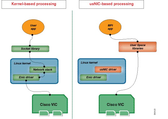
The Cisco user-space NIC (Cisco usNIC) feature improves the performance of software applications that run on the Cisco UCS servers in your data center by bypassing the kernel when sending and receiving networking packets. The applications interact directly with a Cisco UCS VIC second generation adapter, such as the Cisco UCS VIC-1280, which improves the networking performance of your high-performance computing cluster. To benefit from Cisco usNIC, your applications must use the Message Passing Interface (MPI) instead of sockets or other communication APIs.
Cisco usNIC offers the following benefits for your MPI applications:
- Provides a low-latency and high-throughput communication transport.
- Employs the standard and application-independent Ethernet protocol.
-
Takes advantage of lowlatency forwarding, Unified Fabric, and integrated management support in the following Cisco data center platforms:
Standard Ethernet applications use user-space socket libraries, which invoke the networking stack in the Linux kernel. The networking stack then uses the Cisco eNIC driver to communicate with the Cisco VIC hardware. The following figure shows the contrast between a regular software application and an MPI application that uses usNIC.
Configuring Cisco usNIC Using the Cisco IMC GUI
Note |
Even though several properties are listed for Cisco usNIC in the usNIC properties dialog box, you must configure only the following properties because the other properties are not currently being used. |
You must log in to the Cisco IMC GUI with administrator privileges to perform this task.
| Step 1 | Log into the
Cisco IMC
GUI.
For more information about how to log into Cisco IMC, see the Cisco UCS C-Series Servers Integrated Management Controller GUI Configuration Guide available at this URL: http://www.cisco.com/en/US/products/ps10739/products_installation_and_configuration_guides_list.html . |
||||||||
| Step 2 | In the Navigation pane, click the Server tab. | ||||||||
| Step 3 | On the Server tab, click Inventory. | ||||||||
| Step 4 | In the Inventory pane, click the Cisco VIC Adapters tab. | ||||||||
| Step 5 | In the
Adapter Cards area, select the adapter card.
If the server is powered on, the resources of the selected adapter card appear in the tabbed menu below the Adapter Cards area. |
||||||||
| Step 6 | In the tabbed menu below the Adapter Cards area, click the vNICs tab. | ||||||||
| Step 7 | In the
Host
Ethernet Interfaces area, select a vNIC from the table.
|
||||||||
| Step 8 | Click usNIC to open the usNIC Properties dialog box. | ||||||||
| Step 9 | In the
usNICs property, specify the number of Cisco usNICs
that you want to create.
Each MPI process that is running on the server requires a dedicated usNIC. You might need to create up to 64 usNICs to sustain 64 MPI processes running simultaneously. We recommend that you create at least as many usNICs, per usNIC-enabled vNIC, as the number of physical cores on your server. For example, if you have 8 physical cores on your server, create 8 usNICs. |
||||||||
| Step 10 | In the
Properties area, update the following fields:
|
||||||||
| Step 11 | Click Apply. | ||||||||
| Step 12 | In the Navigation pane, click the Server tab. | ||||||||
| Step 13 | On the Server tab, click BIOS. | ||||||||
| Step 14 | In the Actions area, click Configure BIOS. | ||||||||
| Step 15 | In the Configure BIOS Parameters dialog box, click the Advanced tab. | ||||||||
| Step 16 | In the
Processor Configuration area, set the following
properties to
Enabled:
|
||||||||
| Step 17 | Click
Save
Changes.
The changes take effect upon the next server reboot. |
Viewing usNIC Properties
| Step 1 | In the Navigation pane, click the Server tab. | ||||||||||||||||||||||||||||||||||||||||
| Step 2 | On the Server tab, click Inventory. | ||||||||||||||||||||||||||||||||||||||||
| Step 3 | In the Inventory pane, click the Cisco VIC Adapters tab. | ||||||||||||||||||||||||||||||||||||||||
| Step 4 | In the
Adapter Cards area, select the adapter card.
If the server is powered on, the resources of the selected adapter card appear in the tabbed menu below the Adapter Cards area. |
||||||||||||||||||||||||||||||||||||||||
| Step 5 | In the tabbed menu below the Adapter Cards area, click the vNICs tab. | ||||||||||||||||||||||||||||||||||||||||
| Step 6 | In the Host Ethernet Interface area, select the usNIC that is assigned to vNIC, to open the usNIC properties dialog box. | ||||||||||||||||||||||||||||||||||||||||
| Step 7 | In the usNIC area, review or update the information in the following fields:
|
||||||||||||||||||||||||||||||||||||||||
| Step 8 | In the Properties area, review or update the information in the following fields:
|
Configuring iSCSI Boot Capability
Configuring iSCSI Boot Capability for vNICs
When the rack-servers are configured in a standalone mode, and when the VIC adapters are directly attached to the Nexus 5000 family of switches, you can configure these VIC adapters to boot the servers remotely from iSCSI storage targets. You can configure Ethernet vNICs to enable a rack server to load the host OS image from remote iSCSI target devices.
To configure the iSCSI boot capability on a vNIC:
- You must log in with admin privileges to perform this task.
- To configure a vNIC to boot a server remotely from an iSCSI storage target, you must enable the PXE boot option on the vNIC.
Note |
You can configure a maximum of 2 iSCSI vNICs for each host. |
Configuring iSCSI Boot Capability on a vNIC
You can configure a maximum of 2 iSCSI vNICs for each host.
| Step 1 | In the Navigation pane, click the Server tab. | ||||||||||||||||||||||||
| Step 2 | On the Server tab, click Inventory. | ||||||||||||||||||||||||
| Step 3 | In the Inventory pane, click the Cisco VIC Adapters tab. | ||||||||||||||||||||||||
| Step 4 | In the
Adapter Cards area, select the adapter card.
If the server is powered on, the resources of the selected adapter card appear in the tabbed menu below the Adapter Cards area. |
||||||||||||||||||||||||
| Step 5 | In the tabbed menu below the Adapter Cards area, click the vNICs tab. | ||||||||||||||||||||||||
| Step 6 | In the Host Ethernet Interfaces area, select a vNIC from the table, and click iSCSI Boot. | ||||||||||||||||||||||||
| Step 7 | In the General Area, update the following fields:
|
||||||||||||||||||||||||
| Step 8 | In the Initiator Area, update the following fields:
|
||||||||||||||||||||||||
| Step 9 | In the Primary Target Area, update the following fields:
|
||||||||||||||||||||||||
| Step 10 | In the Secondary Target Area, update the following fields:
|
||||||||||||||||||||||||
| Step 11 | Click Configure ISCSI. |
Removing iSCSI Boot Configuration from a vNIC
You must log in with admin privileges to perform this task.
| Step 1 | In the Navigation pane, click the Server tab. |
| Step 2 | On the Server tab, click Inventory. |
| Step 3 | In the Inventory pane, click the Cisco VIC Adapters tab. |
| Step 4 | In the
Adapter Cards area, select the adapter card.
If the server is powered on, the resources of the selected adapter card appear in the tabbed menu below the Adapter Cards area. |
| Step 5 | In the tabbed menu below the Adapter Cards area, click the vNICs tab. |
| Step 6 | In the Host Ethernet Interfaces area, select a vNIC from the table, and click iSCSI Boot. |
| Step 7 | In the dialog box that appears, click Unconfigure ISCSI. |
Managing VM FEX
Virtual Machine Fabric Extender
Cisco Virtual Machine Fabric Extender (VM FEX) extends the (prestandard) IEEE 802.1Qbh port extender architecture to virtual machines. In this architecture, each VM interface is provided with a virtual Peripheral Component Interconnect Express (PCIe) device and a virtual port on a switch.
For this release, VM FEX supports the following cards and Operating systems:
Cards - Cisco UCS 1225 Virtual Interface Card
VM FEX is not supported on Microsoft Hyper-V and Red Hat KVM for this release.
Viewing Virtual FEX Properties
| Step 1 | In the Navigation pane, click the Server tab. | ||||||||||||||||
| Step 2 | On the Server tab, click Inventory. | ||||||||||||||||
| Step 3 | In the Inventory pane, click the Cisco VIC Adapters tab. | ||||||||||||||||
| Step 4 | In the
Adapter Cards area, select the adapter card.
If the server is powered on, the resources of the selected adapter card appear in the tabbed menu below the Adapter Cards area. |
||||||||||||||||
| Step 5 | In the tabbed menu below the Adapter Cards area, click the VM FEXs tab. | ||||||||||||||||
| Step 6 | In the Virtual FEXs area, review the following information:
|
||||||||||||||||
| Step 7 | In the Virtual FEXs area, select a VM FEX from the table. | ||||||||||||||||
| Step 8 | Click Properties to open the VM FEX Properties dialog box for the selected VM FEX. | ||||||||||||||||
| Step 9 | In the General Properties area, review the information in the following fields:
|
||||||||||||||||
| Step 10 | In the Ethernet Interrupt area, review the information in the following fields:
|
||||||||||||||||
| Step 11 | In the Ethernet Receive Queue area, review the information in the following fields:
|
||||||||||||||||
| Step 12 | In the Ethernet Transmit Queue area, review the information in the following fields:
|
||||||||||||||||
| Step 13 | In the Completion Queue area, review the information in the following fields:
|
||||||||||||||||
| Step 14 | In the TCP Offload area, review the information in the following fields:
|
||||||||||||||||
| Step 15 | In the Receive Side Scaling area, review the information in the following fields:
|
Managing Storage Adapters
Create Virtual Drive from Unused Physical Drives
You must log in with admin privileges to perform this task.
| Step 1 | In the Navigation pane, click the Storage tab. | ||||||||||||||
| Step 2 | On the Storage tab, click the appropriate LSI MegaRAID controller. | ||||||||||||||
| Step 3 | On the Work pane, click the Virtual Drive Info tab. | ||||||||||||||
| Step 4 | In the Actions area, click Create Virtual Drive from Unused Physical Drives.
The Create Virtual Drive from Unused Physical Drives dialog box displays. |
||||||||||||||
| Step 5 | In the Create Virtual Drive from Unused Physical Drives dialog box, select the RAID level for the new virtual drives:
This can be one of the following: |
||||||||||||||
| Step 6 | In the Create Drive Groups area, choose one or more physical drives to include in the group.
Use the >> button to add the drives to the Drive Groups table. Use the << button to remove physical drives from the drive group.
|
||||||||||||||
| Step 7 | In the Virtual Drive Properties area, update the following properties:
|
||||||||||||||
| Step 8 | Click Create Virtual Drive. |
Create Virtual Drive from an Existing Drive Group
You must log in with admin privileges to perform this task.
| Step 1 | In the Navigation pane, click the Storage tab. | ||||||||||||||
| Step 2 | On the Storage tab, click the appropriate LSI MegaRAID controller. | ||||||||||||||
| Step 3 | On the Work pane, click the Controller Info tab. | ||||||||||||||
| Step 4 | In the Actions area, click Create Virtual Drive from an Existing Virtual Drive Group.
The Create Virtual Drive from an Existing Virtual Drive Group dialog box displays. |
||||||||||||||
| Step 5 | In the Create Virtual Drive from an Existing Virtual Drive Group dialog box, select the virtual drive whose drive group you want to use to create a new virtual drive. | ||||||||||||||
| Step 6 | In the Virtual Drive Properties area, update the following properties:
|
||||||||||||||
| Step 7 | Click Create Virtual Drive. |
Importing Foreign Configuration
When one or more physical drives that have previously been configured with a different controller are inserted into a server, they are identified as foreign configurations. You can import these foreign configurations to a controller.
You must log in with admin privileges to perform this task.
Clearing Foreign Configuration
This task clears all foreign configuration on the controller. Also, all configuration information from all physical drives hosting foreign configuration is deleted. This action cannot be reverted.
You must log in with admin privileges to perform this task.
Clearing a Boot Drive
This task clears the boot drive configuration on the controller. This action cannot be reverted.
You must log in with admin privileges to perform this task.
Enabling JBOD
Disabling JBOD
JBOD option must be enabled for the selected controller.
Preparing a Drive for Removal
Note |
You can perform this task only on physical drives that display the Unconfigured Good status. |
You must log in with admin privileges to perform this task.
| Step 1 | In the Navigation pane, click the Storage tab. |
| Step 2 | On the Storage tab, click the appropriate LSI MegaRAID controller. |
| Step 3 | On the Work pane, click the Physical Drive Info tab. |
| Step 4 | In the Physical Drives area, select the drive you want to remove. |
| Step 5 | In the Actions area, click Prepare for Removal. |
| Step 6 | Click OK to confirm. |
Retrieving TTY Logs for a Controller
This task retrieves the TTY logs for the controller and places it in the /var/log location. This ensures that this log data is available when Technical Support Data is requested.
You must log in with admin privileges to perform this task.
| Step 1 | In the Navigation pane, click the Storage tab. |
| Step 2 | On the Storage tab, click the appropriate LSI MegaRAID controller. |
| Step 3 | On the Work pane, click the Controller Info tab. |
| Step 4 | In the Actions area, click Get TTY Log. |
| Step 5 | Click
OK to confirm.
Retrieving TTY logs for a controller could take up to 2-4 minutes. Until this process is complete, do not initiate exporting technical support data. |
Undo Preparing a Drive for Removal
You must log in with admin privileges to perform this task.
| Step 1 | In the Navigation pane, click the Storage tab. |
| Step 2 | On the Storage tab, click the appropriate LSI MegaRAID controller. |
| Step 3 | On the Work pane, click the Physical Drive Info tab. |
| Step 4 | In the Physical Drives area, select a drive with a status of Ready to Remove. |
| Step 5 | In the Actions area, click Undo Prepare for Removal. |
| Step 6 | Click OK to confirm. |
Making a Dedicated Hot Spare
You must log in with admin privileges to perform this task.
| Step 1 | In the Navigation pane, click the Storage tab. | ||||||||
| Step 2 | On the Storage tab, click the appropriate LSI MegaRAID controller. | ||||||||
| Step 3 | On the Work pane, click the Physical Drive Info tab. | ||||||||
| Step 4 | In the Physical Drives area, select the physical drive you want to make a dedicated hot spare. | ||||||||
| Step 5 | In the Actions area, click Make Dedicated Hot Spare.
The Make Dedicated Hot Spare dialog box displays. |
||||||||
| Step 6 | In the Virtual Drive Details area, update the following properties:
|
||||||||
| Step 7 | Click Make Dedicated Hot Spare to confirm. |
Making a Global Hot Spare
You must log in with admin privileges to perform this task.
| Step 1 | In the Navigation pane, click the Storage tab. |
| Step 2 | On the Storage tab, click the appropriate LSI MegaRAID controller. |
| Step 3 | On the Work pane, click the Physical Drive Info tab. |
| Step 4 | In the Physical Drives area, select the physical drive you want to make a global hot spare. |
| Step 5 | In the Actions area, click Make Global Hot Spare. |
Removing a Drive from Hot Spare Pools
You must log in with admin privileges to perform this task.
| Step 1 | In the Navigation pane, click the Storage tab. |
| Step 2 | On the Storage tab, click the appropriate LSI MegaRAID controller. |
| Step 3 | On the Work pane, click the Physical Drive Info tab. |
| Step 4 | In the Physical Drives area, select the global or dedicated hot spare you want to remove from the hot spare pools. |
| Step 5 | In the Actions area, click Remove From Hot Spare Pools. |
Toggling Physical Drive Status
| Step 1 | In the Navigation pane, click the Storage tab. |
| Step 2 | On the Storage tab, click the appropriate LSI MegaRAID controller. |
| Step 3 | On the Work pane, click the Physical Drive Info tab. |
| Step 4 | In the Physical Drives area, select the drive you want to set as unconfigured good. |
| Step 5 | In the Actions area, click Set State as Unconfigured Good. |
| Step 6 | Click
OK to confirm that the JBOD mode be disabled.
The Set State as JBOD option is enabled. |
| Step 7 | To enable the JBOD mode for the physical drive, click Set State as JBOD. |
| Step 8 | Click
OK to confirm.
The Set State as Unconfigured Good option is enabled. |
Setting a Physical Drive as a Controller Boot Drive
| Step 1 | In the Navigation pane, click the Storage tab. |
| Step 2 | On the Storage tab, click the appropriate LSI MegaRAID controller. |
| Step 3 | On the Work pane, click the Physical Drive Info tab. |
| Step 4 | In the Physical Drives area, select the drive you want to set as boot drive for the controller. |
| Step 5 | In the Actions area, click Set as Boot Drive. |
| Step 6 | Click OK to confirm. |
Initializing a Virtual Drive
All data on a virtual drive is lost when you initialize the drive. Before you run an initialization, back up any data on the virtual drive that you want to save.
You must log in with admin privileges to perform this task.
| Step 1 | In the Navigation pane, click the Storage tab. | ||||||||
| Step 2 | On the Storage tab, click the appropriate LSI MegaRAID controller. | ||||||||
| Step 3 | On the Work pane, click the Virtual Drive Info tab. | ||||||||
| Step 4 | In the Virtual Drives area, choose the drive that you want to initialize. | ||||||||
| Step 5 | In the Actions area, click Initialize.
The Initialize Virtual Drive dialog box displays. |
||||||||
| Step 6 | Choose the type of initialization you want to use for the virtual drive.
This can be one of the following: |
||||||||
| Step 7 | Click Initialize VD to initialize the drive, or Cancel to close the dialog box without making any changes. | ||||||||
| Step 8 | To view the status of the task running on the drive, in the Operations area, click Refresh.
The following details are displayed:
|
Set as Boot Drive
You must log in with admin privileges to perform this task.
| Step 1 | In the Navigation pane, click the Storage tab. |
| Step 2 | On the Storage tab, click the appropriate LSI MegaRAID controller. |
| Step 3 | On the Work pane, click the Virtual Drive Info tab. |
| Step 4 | In the Virtual Drives area, choose the drive from which the controller must boot. |
| Step 5 | In the Actions area, click Set as Boot Drive. |
| Step 6 | Click OK to confirm. |
Editing a Virtual Drive
| Step 1 | In the Navigation pane, click the Storage tab. | ||||||
| Step 2 | On the Storage Adapters pane, click LSI MegaRAID SAS 9266-8i. | ||||||
| Step 3 | On the Work pane, click Virtual Drive Info tab. | ||||||
| Step 4 | In the Actions area, click Edit Virtual Drive. | ||||||
| Step 5 | Review the instructions, and then click OK. The Edit Virtual Drive dialog box displays. | ||||||
| Step 6 | From the Select RAID Level to migrate drop-down list, choose a RAID level.
See the following table for RAID migration criteria:
|
||||||
| Step 7 | From the Write Policy drop-down list in the Virtual Drive Properties area, choose one of the following:
|
||||||
| Step 8 | Click Save Changes. |
Deleting a Virtual Drive
This task deletes a virtual drive, including the drives that run the booted operating system. So back up any data that you want to retain before you delete a virtual drive.
You must log in with admin privileges to perform this task.
| Step 1 | In the Navigation pane, click the Storage tab. |
| Step 2 | On the Storage tab, click the appropriate LSI MegaRAID controller. |
| Step 3 | On the Work pane, click the Virtual Drive Info tab. |
| Step 4 | In the Virtual Drives area, select the virtual drive you want to delete. |
| Step 5 | In the Actions area, click Delete Virtual Drive. |
| Step 6 | Click OK to confirm. |
Enabling Auto Learn Cycle for a Battery Backup Unit
You must log in with admin privileges to perform this task.
| Step 1 | In the Navigation pane, click the Storage tab. |
| Step 2 | On the Storage tab, click the appropriate LSI MegaRAID controller. |
| Step 3 | On the Work pane, click the Battery Backup Unit tab. |
| Step 4 |
From the Actions pane, click Enable Auto Learn Mode.
A dialog prompts you to confirm the task. |
| Step 5 | Click OK. |
Disabling Auto Learn Cycle for a Battery Backup Unit
You must log in with admin privileges to perform this task.
| Step 1 | In the Navigation pane, click the Storage tab. |
| Step 2 | On the Storage tab, click the appropriate LSI MegaRAID controller. |
| Step 3 | On the Work pane, click the Battery Backup Unit tab. |
| Step 4 |
From the Actions pane, click Disable Auto Learn Mode.
A dialog prompts you to confirm the task. |
| Step 5 | Click OK. |
Starting Learn Cycles for a Battery Backup Unit
You must log in with admin privileges to perform this task.
| Step 1 | In the Navigation pane, click the Storage tab. |
| Step 2 | On the Storage tab, click the appropriate LSI MegaRAID controller. |
| Step 3 | On the Work pane, click the Battery Backup Unit tab. |
| Step 4 |
From the Actions pane, click Start Learn Cycle.
A dialog prompts you to confirm the task. |
| Step 5 | Click OK. |
Toggling Locator LED for a Physical Drive
You must log in with admin privileges to perform this task.
Viewing Storage Controller Logs
You must log in with admin privileges to perform this task.
| Step 1 | In the Navigation pane, click the Storage tab. | ||||||||
| Step 2 | On the Storage tab, click the appropriate LSI MegaRAID controller. | ||||||||
| Step 3 | On the Work pane, click Storage Log tab and review the following information:
|
Backing Up and Restoring the Adapter Configuration
Exporting the Adapter Configuration
The adapter configuration can be exported as an XML file to a remote server which can be one of the following:
Obtain the remote server IP address.
| Step 1 | In the Navigation pane, click the Server tab. | ||||||||||||
| Step 2 | On the Server tab, click Inventory. | ||||||||||||
| Step 3 | In the Inventory pane, click the Cisco VIC Adapters tab. | ||||||||||||
| Step 4 | In the
Adapter Cards area, select the adapter card.
If the server is powered on, the resources of the selected adapter card appear in the tabbed menu below the Adapter Cards area. |
||||||||||||
| Step 5 | In the tabbed menu below the Adapter Cards area, click the General tab. | ||||||||||||
| Step 6 |
In the Actions area of the
General tab, click Export Configuration.
The Export Adapter Configuration dialog box opens. |
||||||||||||
| Step 7 |
In the Export Adapter Configuration dialog box, update the following fields:
|
||||||||||||
| Step 8 | Click Export Configuration. |
Importing the Adapter Configuration
| Step 1 | In the Navigation pane, click the Server tab. | ||||||||||||
| Step 2 | On the Server tab, click Inventory. | ||||||||||||
| Step 3 | In the Inventory pane, click the Cisco VIC Adapters tab. | ||||||||||||
| Step 4 | In the
Adapter Cards area, select the adapter card.
If the server is powered on, the resources of the selected adapter card appear in the tabbed menu below the Adapter Cards area. |
||||||||||||
| Step 5 | In the tabbed menu below the Adapter Cards area, click the General tab. | ||||||||||||
| Step 6 |
In the Actions area of the
General tab, click Import Configuration.
The Import Adapter Configuration dialog box opens. |
||||||||||||
| Step 7 |
In the Import Adapter Configuration dialog box, update the following fields:
|
||||||||||||
| Step 8 | Click Import Configuration. The adapter downloads the configuration file from the specified path on the TFTP server at the specified IP address. The configuration will be installed during the next server reboot. |
What to Do Next
Reboot the server to apply the imported configuration.
Restoring Adapter Defaults
| Step 1 | In the Navigation pane, click the Server tab. |
| Step 2 | On the Server tab, click Inventory. |
| Step 3 | In the Inventory pane, click the Cisco VIC Adapters tab. |
| Step 4 | In the
Adapter Cards area, select the adapter card.
If the server is powered on, the resources of the selected adapter card appear in the tabbed menu below the Adapter Cards area. |
| Step 5 | In the tabbed menu below the Adapter Cards area, click the General tab. |
| Step 6 | In the Actions area of the General tab, click Reset To Defaults and click OK to confirm. |
Managing Adapter Firmware
Adapter Firmware
A Cisco UCS C-Series network adapter contains the following firmware components:
- Adapter firmware—The main operating firmware, consisting of an active and a backup image, can be installed from the Cisco IMC GUI or CLI interface or from the Host Upgrade Utility (HUU). You can upload a firmware image from either a local file system or a TFTP server.
- Bootloader firmware—The bootloader firmware cannot be installed from the Cisco IMC GUI or CLI. You can install this firmware using the Host Upgrade Utility.
Installing Adapter Firmware From a Local File
Store the adapter firmware file in the file system of the managing computer.
| Step 1 | In the Navigation pane, click the Server tab. |
| Step 2 | On the Server tab, click Inventory. |
| Step 3 | In the Inventory pane, click the Cisco VIC Adapters tab. |
| Step 4 | In the
Adapter Cards area, select the adapter card.
If the server is powered on, the resources of the selected adapter card appear in the tabbed menu below the Adapter Cards area. |
| Step 5 | In the tabbed menu below the Adapter Cards area, click the General tab. |
| Step 6 | In the Actions area of the General tab, click Install Firmware to open the Install Adapter Firmware dialog box. |
| Step 7 | In the Install Adapter Firmware dialog box, select Install from local file, then click Next. |
| Step 8 | Click Browse... and locate the adapter firmware file. |
| Step 9 | Click Install Firmware. |
What to Do Next
To activate the new firmware, see Activating Adapter Firmware.
Installing Adapter Firmware From a Remote Server
| Step 1 | In the Navigation pane, click the Server tab. | ||||||||||||||||||
| Step 2 | On the Server tab, click Inventory. | ||||||||||||||||||
| Step 3 | In the Inventory pane, click the Cisco VIC Adapters tab. | ||||||||||||||||||
| Step 4 | In the
Adapter Cards area, select the adapter card.
If the server is powered on, the resources of the selected adapter card appear in the tabbed menu below the Adapter Cards area. |
||||||||||||||||||
| Step 5 | In the tabbed menu below the Adapter Cards area, click the General tab. | ||||||||||||||||||
| Step 6 | In the Actions area of the General tab, click Install Firmware to open the Install Adapter Firmware dialog box. | ||||||||||||||||||
| Step 7 | In the Install Adapter Firmware dialog box, select Install from Remote Server, then click Next. | ||||||||||||||||||
| Step 8 |
In the Install Adapter Firmware dialog box, update the following fields:
|
||||||||||||||||||
| Step 9 | Click Install Firmware. |
What to Do Next
To activate the new firmware, see Activating Adapter Firmware.
Activating Adapter Firmware
| Step 1 | In the Navigation pane, click the Server tab. |
| Step 2 | On the Server tab, click Inventory. |
| Step 3 | In the Inventory pane, click the Cisco VIC Adapters tab. |
| Step 4 | In the
Adapter Cards area, select the adapter card.
If the server is powered on, the resources of the selected adapter card appear in the tabbed menu below the Adapter Cards area. |
| Step 5 | In the tabbed menu below the Adapter Cards area, click the General tab. |
| Step 6 | In the Actions area of the General tab, click Activate Firmware to open the Activate Adapter Firmware dialog box. |
| Step 7 | In the Activate Adapter Firmware dialog box, select the image to run the next time the firmware starts up. |
| Step 8 | Click Activate Adapter Firmware. |
Resetting the Adapter
| Step 1 | In the Navigation pane, click the Server tab. | ||
| Step 2 | On the Server tab, click Inventory. | ||
| Step 3 | In the Inventory pane, click the Cisco VIC Adapters tab. | ||
| Step 4 | In the
Adapter Cards area, select the adapter card.
If the server is powered on, the resources of the selected adapter card appear in the tabbed menu below the Adapter Cards area. |
||
| Step 5 | In the tabbed menu below the Adapter Cards area, click the General tab. | ||
| Step 6 | In the Actions area of the General tab, click Reset and click Yes to confirm.
|
 Feedback