Cisco R-Series Rack and RP-Series PDU Installation Guide
Bias-Free Language
The documentation set for this product strives to use bias-free language. For the purposes of this documentation set, bias-free is defined as language that does not imply discrimination based on age, disability, gender, racial identity, ethnic identity, sexual orientation, socioeconomic status, and intersectionality. Exceptions may be present in the documentation due to language that is hardcoded in the user interfaces of the product software, language used based on RFP documentation, or language that is used by a referenced third-party product. Learn more about how Cisco is using Inclusive Language.
- Updated:
- January 21, 2011
Chapter: Installing the Cisco R-Series Rack
Installing the Cisco R-Series Rack
Securing the Cisco R-Series Rack to the Floor
For information about how to unpack and place the Cisco R-Series Rack, refer to Unpacking a Cisco R-Series Rack. Once the Cisco R-Series Rack is off the pallet, roll it to the desired location. To assure you have enough room at the intended location, refer to the footprint diagram (Figure 2-2).
Complete the following steps to lower the leveling feet and install the front stabilizer bracket:
Step 1![]() Use a flat-head screwdriver to lower each of the leveling feet so that they touch the floor (refer to Figure 3-3 if needed). The rack casters support the weight of the rack, while the leveling feet prevent the rack from rolling.
Use a flat-head screwdriver to lower each of the leveling feet so that they touch the floor (refer to Figure 3-3 if needed). The rack casters support the weight of the rack, while the leveling feet prevent the rack from rolling.

Step 2![]() Remove the stabilizer plate from the bottom floor of the rack.
Remove the stabilizer plate from the bottom floor of the rack.
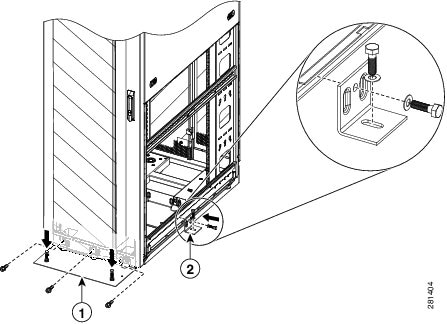
Step 3![]() Attach the stabilizer plate to the front of the Cisco R-Series Rack with the bolts in the accessory kit. (Refer to Figure 4-1, callout 1.)
Attach the stabilizer plate to the front of the Cisco R-Series Rack with the bolts in the accessory kit. (Refer to Figure 4-1, callout 1.)
Figure 4-1 Attaching the Rack to the Floor
Step 4![]() If this is a stand-alone rack that will be loaded with less than 68 kg (150 lb.) of equipment, complete the following steps:
If this is a stand-alone rack that will be loaded with less than 68 kg (150 lb.) of equipment, complete the following steps:
b.![]() Attach the side stabilizer brackets to the center cage nut on each side of the rack using the provided hex bolts and washers. (Refer to Figure 4-1, callout 2.)
Attach the side stabilizer brackets to the center cage nut on each side of the rack using the provided hex bolts and washers. (Refer to Figure 4-1, callout 2.)
Step 5![]() Bolt the Cisco R-Series Rack to the floor surface through the holes in the front and side stabilizer brackets and reinstall the side panels.
Bolt the Cisco R-Series Rack to the floor surface through the holes in the front and side stabilizer brackets and reinstall the side panels.
The Cisco R-Series Rack itself is now installed. You may now:
- Join additional racks to the installed rack as described in “Joining Cisco R42610 Racks into a Suite”
- Install optional Cisco PDUs as described in Chapter 5, “Installing a Cisco RP-Series PDU (Optional)”
- Install devices in the rack as described in their documentation.
Joining Cisco R42610 Racks into a Suite
Available for your Cisco R42610 Racks is an optional rack joining kit (RACK-JOIN-001) with all the hardware required for you to attach two or more racks together. You do not have to remove the doors to attach the racks together. Joining racks into a suite will remove the need for the side stabilizers.
Before you join racks together in a suite, make sure that the floor will support the weight of all the equipment and the racks themselves.
To attach Cisco R42610 Racks together, follow these steps:
Step 1![]() Install the first rack as described in “Securing the Cisco R-Series Rack to the Floor”.
Install the first rack as described in “Securing the Cisco R-Series Rack to the Floor”.
Step 2![]() Remove all doors as described in “Removing and Installing a Front Door” and “Removing and Installing Rear Doors”.
Remove all doors as described in “Removing and Installing a Front Door” and “Removing and Installing Rear Doors”.
Step 3![]() Secure the racks together using the bracket as shown in Figure 4-2. Use two brackets in the front and two in the rear of the rack.
Secure the racks together using the bracket as shown in Figure 4-2. Use two brackets in the front and two in the rear of the rack.
Figure 4-2 Connecting Two Racks

Step 4![]() Install the front stabilizer for the rack you have just added as described in “Securing the Cisco R-Series Rack to the Floor”.
Install the front stabilizer for the rack you have just added as described in “Securing the Cisco R-Series Rack to the Floor”.
Step 5![]() Repeat this procedure to attach additional racks to the suite.
Repeat this procedure to attach additional racks to the suite.
Installing Devices in the Rack
Installation instructions on the optional Cisco PDUs are located in Chapter5, “Installing a Cisco RP-Series PDU (Optional)”
Refer to the documentation for the devices you intend to install. Always observe the following guidelines:
- A list of Cisco products that have been tested with Cisco R-Series Racks is maintained on an internal Cisco website. Please contact your Cisco representative to access the latest information.
- Prior to the certification of components to ship pre racked, a component must be shipped in its original packaging. The shipment of a non-certified component in a rack will void the warranty. Please contact your Cisco representative to determine whether a component has been certified to ship pre racked.
- Always install devices in the bottom of the rack first, heaviest devices in the lowest possible RU space. A top heavy rack can be extremely dangerous.
- If installed devices can slide forward, only extend one device at a time. Never extend any device that weighs over 176 pounds (80 kilograms).
- Never install devices that are not approved by independent national safety labs appropriate for your country.
- Do not use the top of a rack-mounted device as a shelf unless it is intended for that use.
 Feedback