Understanding UCS Server Configuration Utility User Interface
The UCS-SCU GUI is a web-based management interface that allows you to perform tasks such as operating system installation, RAID configuration, and firmware updates.
License Agreement
After UCS-SCU boots up, the first interface is the End User License Agreement. Select I Accept and click Next to agree to this license.
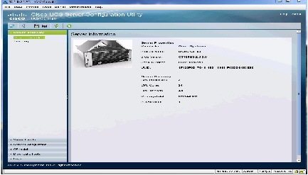
UCS-SCU GUI Home Page
Figure 3-1 shows the UCS-SCU GUI and the different elements in the GUI and Table 3-1 shows the description of each element.
|
|
|
|---|---|
Displays on the left side in the UCS-SCU user interface. See Table 3-2 for a description of all the navigation pane elements. |
|
Displays on the left-hand top corner and has a set of icons. See Table 3-3 for a description of all the toolbar icons. |
|
Opens a window in the application that displays context-sensitive help for the displayed page. |
|
Displays on the right side of the GUI. Different pages appear on the content pane depending on the tab that you select in the Navigation Pane. |
|
Provides details of tests passed, tests in the queue, and tests failed. Viewed only when Diagnostic Tools is selected. |
This section includes the following topics:
Navigation Pane
Table 3-2 describes the elements in the Navigation Pane.
|
|
|
|---|---|
Displays the server information and inventory. Contains links to the following pages: For more information about Server Inventory, go to Chapter4, “Viewing Server Inventory” |
|
Displays the health of the subsystems on your server such as CPUs, memory, power supplies, fans, storage, PCI devices, BIOS, and Cisco IMC. For more information about Server Health, go to Chapter 5, “Viewing Server Health” |
|
Configures a RAID volume on attached hard drives of your server. Contains links to the RAID configuration pages: For more information about Server Configuration, go to Chapter 8, “Configuring RAID Levels” |
|
Installs the RHEL, SLES, Windows, and ESXi operating systems in a fully unattended mode. The most recent drivers for all onboard components are added from the Tools and Drivers CD or from other supported locations during the operating system installation. For more information about OS Install, go to Chapter 7, “Installing Operating Systems” |
|
Allows you to run various types of diagnostic tests to detect server failure. For more information about Diagnostic Tools, go to Chapter 6, “Diagnostic Tools” |
|
Displays the System Log and System Event Log of your server. Contains links to the following pages: For more information about Logs, go to Chapter9, “Viewing Logs” |
Toolbar Pane
Table 3-3 lists and describes all the UCS-SCU icons that you can use to perform specific tasks.


Configuring a Network
To configure a network, follow these steps:
Step 1![]() Click the Network Configuration button on the toolbar.
Click the Network Configuration button on the toolbar.
The Network Configuration dialog box appears.
Step 2![]() In the Network Configuration dialog box, do the following:
In the Network Configuration dialog box, do the following:
a.![]() Select IP Address from DHCP server or Static IP Address. If you select Static IP Address, do the following:
Select IP Address from DHCP server or Static IP Address. If you select Static IP Address, do the following:
–![]() In the IP Address field, enter the IPv4 address.
In the IP Address field, enter the IPv4 address.
–![]() In the Subnet Mask field, enter the subnet IPv4 address.
In the Subnet Mask field, enter the subnet IPv4 address.
–![]() In the Gateway field, enter the gateway IPv4 address.
In the Gateway field, enter the gateway IPv4 address.
–![]() (Optional) In the DNS field, enter the DNS IPv4 address.
(Optional) In the DNS field, enter the DNS IPv4 address.

Note![]() Go to Step b. if you want to download software and drivers from cisco.com.
Go to Step b. if you want to download software and drivers from cisco.com.
b.![]() Select Direct Connection to internet or Manual Proxy. If you select Manual Proxy, do the following:
Select Direct Connection to internet or Manual Proxy. If you select Manual Proxy, do the following:
–![]() In the HTTP Proxy Server URL field, enter the URL of the proxy server. The maximum limit is 45 characters.
In the HTTP Proxy Server URL field, enter the URL of the proxy server. The maximum limit is 45 characters.
–![]() In the Port field, enter the port number. The maximum limit is 5 characters. By default, it is 8080.
In the Port field, enter the port number. The maximum limit is 5 characters. By default, it is 8080.
–![]() In the Proxy Server UserName field, enter the user name of the proxy server. The maximum limit is 45 characters.
In the Proxy Server UserName field, enter the user name of the proxy server. The maximum limit is 45 characters.
–![]() In the Proxy Server Password field, enter the password of the proxy server. The maximum limit is 45 characters.
In the Proxy Server Password field, enter the password of the proxy server. The maximum limit is 45 characters.
Step 3![]() Click Configure to save the settings.
Click Configure to save the settings.
Network configuration is a one-time process, and if you have not configured your network, you are prompted to configure it during the following procedures:
- When you are updating images to Cisco Flexible Flash.
- When you are downloading drivers from the network share or cisco.com during the operating system installation. (See “Installation Drivers” section).
Performing Server Health Check
The Probe Server functionality allows to perform a health check of the server subsystems. When you click the Probe Server icon, the server health check is initiated.
To view the health check results, click the Server Health tab in the navigation pane.
For more information about the Server Health tab, go to Chapter 5, “Viewing Server Health”.
Saving Logs
You can use the Save Logs functionality to save your log files. Before using Save Logs, you must insert a USB flash drive or vMedia for storing the log files.
Using Server Snapshot
You can use the Server Snapshot feature in the UCS SCU user interface to take a point-in-time inventory of a server. This feature allows you to compare inventories or components of a server over certain periods of time. Before you initiate a server snapshot, be sure that you connect a USB flash drive into the server. Without a flash drive available, the log file created by the server snapshot is not saved.
When you initiate a server snapshot, UCS SCU retrieves information on the server components, and also runs a series of quick tests to determine the state of the server. When you initiate a server snapshot, a series of quick tests such as processor, memory, disk, cache, network interface tests, QPI Link and Trafffic, LSI Battery backup and RAID adapter tests, and Chipset tests, are performed on the server.
The time to complete a server snapshot process depends on the server configuration such as installed memory, the number of physical disks and their sizes, and the number of network interfaces. This process could complete in 30-45 minutes or could a few hours.
After the server snapshot process is complete, the log file is saved on to the USB flash drive that you specified. You can open this log file in any editor, for example, WordPad. To help compare server inventories across time periods, we recommend that you store these log files in a location and archive it. When you have multiple log files, you can use a comparison tool from the Internet to view differences in the server inventory.
To take a server snapshot, follow these steps:
Step 1![]() Connect a USB flash drive to the server or through vMedia.
Connect a USB flash drive to the server or through vMedia.
Without this flash drive, you cannot save the server snapshot log file. Be sure that there is adequate space on the flash drive to save the log file.
Step 2![]() Click the Server Snapshot icon in the UCS SCU interface.
Click the Server Snapshot icon in the UCS SCU interface.
A dialog box is displayed that prompts you to insert the USB flash drive.
A dialog box prompts you to select the USB flash drive in which you would like to save the log file.
Step 4![]() Choose the USB flash drive from the drop-down menu and click Save.
Choose the USB flash drive from the drop-down menu and click Save.
The Server Snapshot process is initiated. This process could last up to 20 to 30 minutes. A dialog box indicating the progress of the server snapshot process appears. During this process, you cannot perform any other tasks on the server. At any moment during the process, you can cancel the server snapshot process by clicking Cancel in the dialog box.
Note![]() During the server snapshot process, if the KVM connection is terminated, it does not terminate the server snapshot process. When you log in again to KVM Console, you will notice that the server snapshot process is still running or has completed. However, if the USB flash drive is connected through vMedia and the KVM connection is terminated, then the server snapshot process is halted as the connection to the USB flash drive is lost.
During the server snapshot process, if the KVM connection is terminated, it does not terminate the server snapshot process. When you log in again to KVM Console, you will notice that the server snapshot process is still running or has completed. However, if the USB flash drive is connected through vMedia and the KVM connection is terminated, then the server snapshot process is halted as the connection to the USB flash drive is lost.
Step 5![]() After the snapshot process is complete, a dialog box message appears to indicate that the server snapshot process is complete. Click OK.
After the snapshot process is complete, a dialog box message appears to indicate that the server snapshot process is complete. Click OK.
The log file is saved on the USB flash drive. The log file is a text file and is saved with the server name, and includes the date when the server snapshot was taken. For example: Server_UCSC-C240-M3S_FCH1716V24S_06_28_2014.txt is the log file name of a server snapshot taken for UCS C-240 server on June 28th, 2014.
Step 6![]() Open this log file with any editor.
Open this log file with any editor.
Note![]() To compare inventory information of the same server over a period of time, we recommend that you archive these log files so that they are always available for comparison.
To compare inventory information of the same server over a period of time, we recommend that you archive these log files so that they are always available for comparison.
While running quick tests on the server, the server snapshot feature can determine only if a server component passed or failed a test. It cannot determine the reasons for a component not passing the quick test. While viewing the log file of the server snapshot process, if you notice that a server component did not pass the quick test, then check the quick test logs available under the Diagnostics Tools.
Note![]() To know more about Diagnostic Tools, go to Chapter6, “Diagnostic Tools”
To know more about Diagnostic Tools, go to Chapter6, “Diagnostic Tools”
The log file of the server snapshot process includes the following information:
- Chassis Summary
- BaseBoard Summary
- Cisco IMC Summary
- Processor Summary
- Memory Summary
- Storage Summary
- PCI Adapter Summary
- Power Supply Summary
- Server diagnostics Quick Test Results
- Server Probe Data
- Server Inventory Data
Synchronizing the Hypervisor Partition
On servers that support the Cisco FlexFlash SD card, UCS-SCU provides an option to synchronize the Hypervisor virtual disk, on the SD card, configured as a RAID-1 disk. This feature is available only when both slots of the Cisco FlexFlash SD card are populated. UCS-SCU detects the presence and absence of SD cards on the server.
When one member slot of the SD card is corrupt, use this option to synchronize the Hypervisor data across two members of the RAID-1 virtual disk. You can initiate this synchronization only if two cards are detected and RAID-1 is determined as unhealthy (one member is corrupt).
Note![]() This functionality is not available for C220 M4 and C240 M4 servers. You can perform this task for these servers from Cisco IMC.
This functionality is not available for C220 M4 and C240 M4 servers. You can perform this task for these servers from Cisco IMC.
To synchronize the Hypervisor virtual disk, follow these steps:
Step 1![]() Click the Hypervisor Sync icon on the toolbar.
Click the Hypervisor Sync icon on the toolbar.
A dialog box prompts you to confirm that you want to synchronize the hypervisor RAID.
When the synchronization is complete, a dialog box indicating the completion of the process is displayed.
The Hypervisor Sync icon on the toolbar is greyed out.
Rebooting the Server
To reboot the server, follow these steps:
Step 1![]() Click the Reboot icon on the toolbar.
Click the Reboot icon on the toolbar.
The Reboot dialog box appears.
The server is rebooted, and the UCS-SCU GUI reappears.
 Feedback