Upgrading Cisco UCS Hardware
This chapter includes the following sections:
- Upgrading Fabric Interconnects
- Upgrading I/O Modules
- Upgrading Adapter Cards
- Upgrading Integrated Rack-Mount Servers
Upgrading Fabric Interconnects
Fabric Interconnect Upgrade Considerations
Be sure the following prerequisites are met before beginning any procedures in this section:
 Caution |
All software and firmware on all components must be upgraded to the latest software release and build available before attempting an upgrade. UCS software version 2.0 is the bare minimum version for the Cisco UCS 6248 UP. The new Cisco UCS 6200 series fabric interconnects must be loaded with the same build version that is on the Cisco UCS 6100 series fabric interconnect it will replace. |
Caution |
If you intend to implement the fabric port channel feature available in UCS software version 2.0 after performing the hardware upgrade, you may need to rearrange the cabling between I/O module and Fabric Interconnect before performing the feature configuration. Fabric port channel will require that all physical links from a given I/O module physically connect to a contiguous block of ports (1-8 or 9-16, and so on). See http://www.cisco.com/en/US/products/ps10281/products_installation_and_configuration_guides_list.html. This feature requires a UCS 2200 Series I/O Module connecting to a UCS 6200 Series Fabric Interconnect. |
- Upgrading the fabric interconnect should be done before upgrading to a new IO Module or virtual interface card.
- Do not attempt to implement new software features from the new UCS software version until all required hardware is installed.
- Changes to the topology like number of server or uplink connections should be performed after the fabric interconnect upgrade is complete.
- Make a detailed record of the cabling between IO Modules and fabric interconnects using the provided table. You will need to preserve the physical port mapping to maintain the server pinning already configured and minimize down time. See Table 1.
- For a cluster configuration, both fabric interconnects must have symmetrical connection topologies between fabric interconnect and IO Modules.
- Standalone installations should expect down time. Upgrading a fabric interconnect is inherently traffic disruptive.
- A best practice would be to perform a full configuration and software backup before performing this hardware upgrade.
Port Mapping for Upgrades
The upgrade described here is primarily for upgrading a Cisco UCS 6120 fabric interconnect to a Cisco UCS 6248. If you have a Cisco UCS 6140 fabric interconnect that has 48 or less physical ports connected, you will also be able to utilize these steps, the same principles will apply though you will have to manually map any ports connected to slot 3 on a UCS 6140 as the UCS 6248 has no slot 3. The same considerations will also apply when upgrading a Cisco UCS 6140 fabric interconnect to a Cisco UCS 6296, though as the 6296 has enough slots that no manual re-mapping will be necessary.
Fixed Ports
On the UCS 6120 fabric interconnect, the fixed ports on slot 1 are all ethernet ports, which might be further configured as Server ports or uplink Ethernet ports. On the UCS 6248 fabric interconnect, you can separate the 32 physical ports in slot one into two contiguous pools, low numbered ports being Ethernet ports and high numbered ports being Fibre Channel ports. When upgrading to a UCS 6248, the UCS 6120 port mappings can be directly carried over on fixed ports with no reconfiguration required. When upgrading a UCS 6140 to a UCS 6296. the port mappings can be directly carried over on fixed ports with no reconfiguration required.
 Note |
Since a UCS 6140 has 40 ports on slot 1 and a UCS 6248 has 32 ports, any ports currently configured on ports 1/33 to 1/40 of the UCS 6140 will have to be moved during the upgrade process. |
Caution |
If you ever need to change the pool sizes for slot 1 this will require a reboot of the fabric interconnect which can lead to a service disruption. If you ever need to change the pool sizes for slot 2 this will require a reset of the expansion module in slot 2. To minimize disruption, plan to have at least a few Ethernet uplink and Fibre Channel uplink ports configured on Slot 1. Implement this fail safe after the upgrade is complete and the system re-stabilizes. |
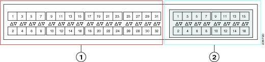
1 |
Slot 1, 32 fixed universal ports |
2 |
Slot 1, 16 expansion universal ports |
Expansion Ports
On the UCS 6120 fabric interconnect, the expansion slot port types depend on which of four possible expansion modules are installed. On the UCS 6248 fabric interconnect, you can separate the 16 physical ports in an expansion slot into two pools, low numbered ports being Ethernet ports and high numbered ports being Fibre Channel, see the Cisco UCS Manager configuration guides. When upgrading to a UCS 6248 or UCS 6296, you may need to pre- plan and re-configure expansion module port mappings before powering up the new interconnect.
Note |
Any expansion ports in slot 3 of a UCS 6140 fabric interconnect will need to have their configuration deleted and their use re-mapped to ports on slots 1 or 2 of the new UCS 6248. Upgrading a UCS 6140 to a UCS 6296 is the preferred path as this manual re-mapping will note be necessary. |
-
If you have an N10-E0080 or N10-E0060 Fibre channel expansion module in your UCS 6120, the existing fibre channel configurations can simply carry over to the new UCS 6248, though this may not be appropriate for all situations as it will mean that all ports in slot two are fibre channel. If you want to reconfigure ports 2/1 to 2/8 to use ports 2/9 to 2/16, do so after the upgrade is completed.
Figure 2. Cisco UCS 6120 Port Numbering when Configured with the N10-E0080 Expansion Module

A
Slot 1, ports 1 through 8: 10-Gigabit or 1 Gigabit Ethernet capable ports
C
Slot 2 Fibre Channel ports 1 through 8
B
Slot 1, ports 1 through 20: 10-Gigabit Ethernet ports
Figure 3. Cisco UCS 6120 Port Numbering when Configured with the N10-E0060 Expansion Module

A
Slot 1, ports 1 through 8: 10-Gigabit or 1 Gigabit Ethernet capable ports
C
Slot 2 Fibre Channel ports 1 through 6
B
Slot 1, ports 1 through 20: 10-Gigabit Ethernet ports
-
If you have an N10-E0600 Fibre channel expansion module in your UCS 6120, the existing Ethernet configurations can simply carry over to the UCS 6248, with ports 2/7 to 2/16 potentially configurable for either Ethernet or FC.
Figure 4. Cisco UCS 6120 Port Numbering when Configured with the N10-E0600 Expansion Module
A
Slot 1, ports 1 through 8: 10-Gigabit or 1 Gigabit Ethernet capable unencrypted ports
C
Slot 2 10-Gigabit Ethernet ports 1 through 6
B
Slot 1, ports 1 through 20: 10-Gigabit Ethernet ports
-
If you have an N10-E0440 expansion module in your UCS 6120, the simplest direct mapping would be to allow Ethernet ports 2/1 to 2/4 on the UCS 6248 to carry over, then remap the fibre channel ports to new port numbers on either slot 1 or slot 2.
Figure 5. Cisco UCS 6120 Port Numbering when Configured with the N10-E0440 Expansion Module

A
Slot 1, ports 1 through 8: 10-Gigabit or 1 Gigabit Ethernet capable ports
C
Slot 2 10-Gigabit Ethernet ports 1 through 4
B
Slot 1, ports 1 through 20: 10-Gigabit Ethernet ports
D
Slot 2 Fibre Channel ports 1 through 4
Fabric Interconnect Port Connection Record
Fabric Interconnect A/B |
Connected to |
||||||
|---|---|---|---|---|---|---|---|
Slot |
Port |
Chassis |
IOM |
Port |
LAN or SAN Pin Group |
Port Channel Group |
Connection Notes |
1 |
1 |
||||||
2 |
|||||||
3 |
|||||||
4 |
|||||||
5 |
|||||||
6 |
|||||||
7 |
|||||||
8 |
|||||||
9 |
|||||||
10 |
|||||||
11 |
|||||||
12 |
|||||||
13 |
|||||||
14 |
|||||||
15 |
|||||||
16 |
|||||||
17 |
|||||||
18 |
|||||||
19 |
|||||||
20 |
|||||||
21 |
|||||||
22 |
|||||||
23 |
|||||||
24 |
|||||||
25 |
|||||||
26 |
|||||||
27 |
|||||||
28 |
|||||||
29 |
|||||||
30 |
|||||||
31 |
|||||||
32 |
|||||||
2 |
1 |
||||||
2 |
|||||||
3 |
|||||||
4 |
|||||||
5 |
|||||||
6 |
|||||||
7 |
|||||||
8 |
|||||||
9 |
|||||||
10 |
|||||||
11 |
|||||||
12 |
|||||||
13 |
|||||||
14 |
|||||||
15 |
|||||||
16 |
|||||||
Upgrading a Fabric Interconnect Cluster
Caution |
If your UCS 6120 fabric interconnect uses a N10-E0440 expansion module, or if you are migrating a UCS 6140 with an expansion module in slot 3 to a UCS 6248, pre-plan their deletion and re- mapping following the guidelines in the previous section on port maps. |
Unless otherwise noted, for more information about how to perform configuration procedures in Cisco UCS Manager for a particular step, see the Cisco UCS Manager configuration guide for the appropriate release.
| Step 1 |
Mount the replacement fabric interconnects into either the same rack or an adjacent rack. Refer to the Cisco UCS 6200 Series Installation Guide for details. |
| Step 2 |
Using either the UCS manager CLI or GUI, verify the state (subordinate or active) of the fabric interconnects. See Verifying the High Availability Status and Roles of a Cluster Configuration. |
| Step 3 | Back up the software configuration information and the UCS Manager software. |
| Step 4 | Disable the server ports on the subordinate fabric interconnect. |
| Step 5 |
Power down the subordinate fabric interconnect by unplugging it from the power source. If you are monitoring the upgrade using a KVM session, you may need to reconnect the KVM session when you power down the fabric interconnect. |
| Step 6 | Disconnect the cables from the chassis IO Modules or fabric extenders to the subordinate fabric interconnect ports in slot 1 on the old fabric interconnect. |
| Step 7 | Connect these cables into the corresponding ports on slot 1 of one of the new Cisco UCS 6248 UP fabric interconnects, using the connection records to preserve the port mapping and the configured server pinning. |
| Step 8 |
Disconnect the L1/L2, M1 management, and Console cables on the old fabric interconnect. The ports for these connections are on the opposite side of the interconnect, so if your cables are just barely long enough to connect two rack-adjacent UCS 6120 interconnects you will probably need new cables. |
| Step 9 | Connect the M1 management, and Console cables to the new Cisco UCS 6248 UP. |
| Step 10 |
Connect the L1/L2 cables that were disconnected onto the new Cisco UCS 6248 UP. L1 connects to L1, L2 connects to L2. |
| Step 11 | Disconnect the Ethernet or FC cables from slot 2 of the old fabric interconnect. |
| Step 12 |
Connect the Ethernet or FC cables to the corresponding ports in slot 2 of the new Cisco UCS 6248 UP. Some may go to slot 1, depending on the mappings planned out earlier in the process. |
| Step 13 |
Connect the power to the new Cisco UCS 6248 UP, it will automatically boot and run POST tests.
Directly connect the console cable to a terminal and observe the boot sequence. you should at some point see the Basic System Configuration Dialog, where you will configure the switch as a subordinate interconnect. If you do not see this dialog, you either have different builds of software on your old primary and new subordinate, or the new subordinate has previously been part of a cluster and will need to have all configuration information wiped before it can be added to a cluster as a subordinate. In either case, immediately disconnect the L1 and L2 connections and complete the bringup as a standalone fabric interconnect, then correct the issue before proceeding further. |
| Step 14 |
(Optional)Remap UCS 6100 fabric interconnect FC ports 2/1 to 2/4 on a N10-E0440 expansion module or any slot 3 ports onto the new fabric interconnect expansion module.
|
| Step 15 |
The new subordinate fabric interconnect will automatically synchronize the configuration and database/state information from the primary fabric interconnect. Synchronization between primary and subordinate fabric interconnects can take several minutes. The port configuration is copied from the subordinate switch to the new hardware. |
| Step 16 |
Verify that the data path is ready. See Verifying that the Data Path is Ready. Make sure all faults are resolved before proceeding. |
| Step 17 | Enable the server ports that had been disabled in Step 4. |
| Step 18 |
Promote the subordinate fabric interconnect to active, and repeat the process on the second Cisco UCS 6248 UP. Cable the second new fabric interconnect identically to the first, and allow the reconfiguration done to be applied to the second new fabric interconnect as well. |
Upgrading I/O Modules
I/O Module Upgrade Considerations
Be sure the following prerequisites are met before beginning any procedures in this section:
All software and firmware on all components must be upgraded to the same software release available before attempting an upgrade. This release must support the hardware you will be adding. UCS software version 2.0(1) is the bare minimum version for the UCS 2208XP I/O Module. UCS software version 2.0(2) is the bare minimum version for the UCS 2204XP I/O Module.
- Do not attempt to implement new software features from the new UCS software version until all required hardware is installed.
- Make a detailed record of the cabling between I/O Modules and fabric interconnects. You will need to preserve the physical port mapping to maintain the server pinning already configured and minimize down time.
- For a cluster configuration, both fabric interconnects must have symmetrical connection topologies between fabric interconnect and I/O module.
- Standalone installations should expect down time. Upgrading an I/O module will be inherently traffic disruptive.
- When performing hardware upgrades to implement features new to UCS software version 2.0, upgrade the fabric interconnect, then the I/O module, then the adapter in the blade server.
- Cisco I/O modules only support one, two, four, and (UCS 2208 only) eight link topologies between I/O module and fabric interconnect. If there is a link failure on one of the links, UCS falls back to the next largest possible topology with regards to blade to fabric port mapping. If this ever happens, re-acknowledge the chassis, and manually re-map the fabric ports. It is recommended during the replacement of a fabric interconnect that you have all ports connected to the fabric interconnect before the configuration sync.
- A best practice would be to perform a full configuration and database/state information backup before performing this hardware upgrade.
- If you intend to implement the fabric port channel feature available in UCS software version 2.0, you may need to rearrange the cabling between I/O module and fabric interconnect before performing the feature configuration. Fabric port channel will require that all physical links from a given I/O module physically connect to a contiguous block of ports (1-8 or 9-16, and so on). This feature requires a UCS 2200 Series I/O Module connecting to a UCS 6200 Series Fabric Interconnect. See the Cisco UCS Manager configuration guides.
I/O Module Port Connection Record
I/O Module |
Connected to |
||||
|---|---|---|---|---|---|
Number |
Port |
Fabric Interconnect A or B |
Slot |
Port |
Connection Notes |
1 |
1 |
||||
2 |
|||||
3 |
|||||
4 |
|||||
5 |
|||||
6 |
|||||
7 |
|||||
8 |
|||||
2 |
1 |
||||
2 |
|||||
3 |
|||||
4 |
|||||
5 |
|||||
6 |
|||||
7 |
|||||
8 |
|||||
Upgrading an I/O Module
| Step 1 | Connect to the cluster’s fabric interconnect, and verify the state (subordinate or active) of the fabric interconnects. |
| Step 2 | Make a detailed record of the port mapping of the connections between the fabric interconnects and the I/O modules. |
| Step 3 | Disconnect the 10GbE cables connecting the chassis I/O module to the subordinate fabric interconnect on the I/O module side. |
| Step 4 | Loosen the captive screws on the old I/O module’s levers. |
| Step 5 | Pull the levers outward to unseat the old I/O module. |
| Step 6 | Make sure that the two levers at the front of the new I/O module are pulled open. |
| Step 7 | Slide the new I/O module into the I/O module slot, ensuring that the new I/O module is fully seated. |
| Step 8 | Close the levers and tighten the captive screw on each lever. |
| Step 9 | Connect the 10GbE cables into the appropriate ports on the new Cisco UCS 2208UP I/O Module or Cisco UCS 2204UP I/O Module, using the connection records to preserve the port mapping and the configured server pinning. |
| Step 10 |
If you have changed port mappings, you may need to reacknowledge the I/O Module, fabric extender, or rack server connected to the subordinate fabric interconnect. This action will only be necessary if you have changed port mappings, but it will be disruptive if it is needed. See the Cisco UCS Manager configuration guides. |
| Step 11 | Promote the subordinate fabric interconnect to active, and repeat steps 2 to 9 on the second Cisco UCS 2208 UP or Cisco UCS 2204UP I/O Module. |
Upgrading Adapter Cards
Adapter Card Upgrade Considerations
Be sure the following prerequisites are met before beginning any procedures in this section.
All software and firmware on all components must be upgraded to the latest software release available before attempting an upgrade. UCS software version 2.0(1) is the bare minimum version for the Cisco UCS 6248 UP, the UCS 2208 IO Module, and the Cisco UCS Virtual Interface Card 1280. UCS software version 2.0(2) is the bare minimum version for the Cisco UCS 6296 UP and the UCS 2204 IO Module.
- Do not attempt to implement new software features from the new UCS software version until all required hardware is installed.
- You will be able to physically install a Cisco UCS Virtual Interface Card 1280 without first installing a UCS 2208 I/O Module or UCS 2204 I/O Module and additional connections to a fabric interconnect, but to do so would not allow you to take full advantage of the additional performance the Cisco UCS Virtual Interface Card 1280 provides compared to the UCS M81KR. The preferred order is to upgrade the Fabric interconnect, then the I/O Module, and finally the Cisco UCS Virtual Interface Card 1280.
- Blade servers allowing more than one Adapter Card may mix the Cisco UCS Virtual Interface Card 1280 with the UCS M81KR, the M72KR-E, or the M72KR-Q. Dual Cisco UCS Virtual Interface Card 1280 adapters are also supported.
- A best practice would be to perform a full configuration and software backup before performing this hardware upgrade.
- If you intend to implement the fabric port channel feature available in UCS software version 2.0, you may need to rearrange the cabling between IOM and Fabric Interconnect before performing the feature configuration. Fabric port channel will require that all physical links from a given I/O module physically connect to a contiguous block of ports (1-8 or 9-16, and so on). This feature requires a UCS 2200 Series I/O Module connecting to a UCS 6200 Series Fabric Interconnect. See the Fabric Port Channel sections in the configuration guides for more details.
Upgrading an Adapter Card
| Step 1 | Use the locator button in the UCS Manager GUI to confirm which server you are upgrading. |
| Step 2 |
Decommission and remove the blade server using the adapter you wish to upgrade.
|
| Step 3 |
Remove the top cover and remove the old Adapter Card.
|
| Step 4 |
Install the new Adapter card.
|
| Step 5 | Replace the top cover and reinsert the blade server in the chassis. |
| Step 6 | Recommission the server by reacknowledging the server slot. |
| Step 7 | When upgrading a Virtual Interface Card, configurations created for the older card will carry over to the new hardware. Additional configuration is now possible, but no re-configuration is required. |
Upgrading Integrated Rack-Mount Servers
Required Order of Steps for Integrating Cisco UCS Rack-Mount Servers
After you upgrade the firmware for the existing components, you can integrate one or more Cisco UCS rack-mount servers. When you integrate rack-mount servers, you must perform the steps in the following order:
- If you have not already done so, configure the rack server discovery policy in Cisco UCS Manager.
- Follow the instructions in the appropriate rack-mount server installation guide for installing and integrating a rack-mount server in a system managed by Cisco UCS Manager.
- Wait for Cisco UCS Manager to discover the new server. If server discovery does not begin within a few minutes, acknowledge the server.
Upgrades of Integrated Rack-Mount Servers
Cisco UCS, Release 2.0(2) does not support integration with rack-mount servers through Cisco Nexus 2248 FEXes. If you upgrade a Cisco UCS domain that includes integrated rack-mount servers to Release 2.0(2) or later, you must to upgrade your setup to include Cisco Nexus 2232 FEXes.
For more information, see the appropriate rack-mount server installation guide for migrating a rack-mount server integration to Cisco UCS, Release 2.0(2).
 Feedback