LAN Ports and Port Channels

Unified Ports on Cisco UCS 6200 Series and 6300 Series Fabric Interconnects

Unified ports are ports on the Cisco UCS 6200 Series and Cisco UCS 6300 Series Fabric Interconnects that you can configure to carry either Ethernet or Fibre Channel traffic. A Cisco UCS domain cannot use these un-reserved ports until you configure them.


Note


When you configure a port on a fabric interconnect, the administrative state is automatically set to enabled. If the port is connected to another device, this may cause traffic disruption. You can disable the port after configuring it. Configurable beacon LEDs indicate which unified ports are configured for the selected port mode.


Port Modes

The port mode determines whether a unified port on the fabric interconnect is configured to carry Ethernet or Fibre Channel traffic. You configure the port mode in Cisco UCS Manager. However, the fabric interconnect does not automatically discover the port mode.

Changing the port mode deletes the existing port configuration and replaces it with a new logical port. Any objects associated with that port configuration, such as VLANs and VSANS, are also removed. There is no restriction on the number of times you can change the port mode for a unified port.

Port Types

The port type defines the type of traffic carried over a unified port connection.

By default, unified ports changed to Ethernet port mode are set to the Ethernet uplink port type. Unified ports changed to Fibre Channel port mode are set to the Fibre Channel uplink port type. You cannot unconfigure Fibre Channel ports.

Changing the port type does not require a reboot.

Ethernet Port Mode

When you set the port mode to Ethernet, you can configure the following port types:

  • Server ports

  • Ethernet uplink ports

  • Ethernet port channel members

  • FCoE ports

  • Appliance ports

  • Appliance port channel members

  • SPAN destination ports

  • SPAN source ports


    Note


    For SPAN source ports, configure one of the port types and then configure the port as SPAN source.


Fibre Channel Port Mode

When you set the port mode to Fibre Channel, you can configure the following port types:

  • Fibre Channel uplink ports

  • Fibre Channel port channel members

  • Fibre Channel storage ports

  • SPAN source ports


    Note


    For SPAN source ports, configure one of the port types and then configure the port as SPAN source.


Data Traffic Interruption from Port Mode Changing

Port mode changes can cause an interruption to the data traffic for the Cisco UCS domain. The length of the interruption and the affected traffic depend upon the configuration of the Cisco UCS domain and the module on which you made the port mode changes.


Tip


To minimize traffic disruption during system changes, form a Fibre Channel uplink port-channel across the fixed and expansion modules.


Impact of Port Mode on an Expansion Module

After you make port mode changes on an expansion module, the module reboots. All traffic through port on the expansion module is interrupted for approximately 1 minute while the module reboots.

Impact of Port Mode Changes on the Fixed Module in a Cluster Configuration

A cluster configuration has two fabric interconnects. After you make port changes to the fixed module, the fabric interconnect reboots. The impact on the data traffic depends upon whether or not you have configured the server vNICs to failover to the other fabric interconnect when one fails.

If you change the port modes on the expansion module of one fabric interconnect and then wait for that to reboot before changing the port modes on the second fabric interconnect, the following occurs:

  • With server vNIC failover, traffic fails over to the other fabric interconnect and no interruption occurs.

  • Without server vNIC failover, all data traffic through the fabric interconnect on which you changed the port modes is interrupted for approximately eight minutes while the fabric interconnect reboots.

When you change the port modes on the fixed modules of both fabric interconnects simultaneously, all data traffic through the fabric interconnects are interrupted for approximately eight minutes while the fabric interconnects reboot.

Impact of Port Mode Changes on the Fixed Module in a Standalone Configuration

A standalone configuration has only one fabric interconnect. After you make port changes to the fixed module, the fabric interconnect reboots. All data traffic through the fabric interconnect is interrupted for approximately eight minutes while the fabric interconnect reboots.

Guidelines for Configuring Unified Ports

Consider the following guidelines and restrictions when configuring unified ports:

Hardware and Software Requirements

Unified ports are supported on the 6200 series fabric interconnect with Cisco UCS Manager, version 2.0.

Unified ports are not supported on 6100 series fabric interconnects, even if they are running Cisco UCS Manager, version 2.0.

Port Mode Placement

Because the Cisco UCS Manager GUI interface uses a slider to configure the port mode for unified ports on a fixed or expansion module, it automatically enforces the following restrictions which limits how port modes can be assigned to unified ports. When using the Cisco UCS Manager CLI interface, these restrictions are enforced when you commit the transaction to the system configuration. If the port mode configuration violates any of the following restrictions, the Cisco UCS Manager CLI displays an error:

  • Ethernet ports must be grouped together in a block. For each module (fixed or expansion), the Ethernet port block must start with the first port and end with an even numbered port.

  • Fibre Channel ports must be grouped together in a block. For each module (fixed or expansion), the first port in the Fibre Channel port block must follow the last Ethernet port and extend to include the rest of the ports in the module. For configurations that include only Fibre Channel ports, the Fibre Channel block must start with the first port on the fixed or expansion module.

  • Alternating Ethernet and Fibre Channel ports is not supported.

Example of a valid configuration— Might include unified ports 1–16 on the fixed module configured in Ethernet port mode and ports 17–32 in Fibre Channel port mode. On the expansion module you could configure ports 1–4 in Ethernet port mode and then configure ports 5–16 in Fibre Channel mode. The rule about alternating Ethernet and Fibre Channel port types is not violated because this port arrangement complies with the rules on each individual module.

Example of an invalid configuration— Might include a block of Fibre Channel ports starting with port 16. Because each block of ports has to start with an odd-numbered port, you would have to start the block with port 17.

The total number of uplink Ethernet ports and uplink Ethernet port channel members that can be configured on each fabric interconnect is limited to 31. This limitation includes uplink Ethernet ports and uplink Ethernet port channel members configured on the expansion module.

Special Considerations for UCS Manager CLI Users

Because the Cisco UCS Manager CLI does not validate port mode changes until you commit the buffer to the system configuration, it is easy to violate the grouping restrictions if you attempt to commit the buffer before creating at least two new interfaces. To prevent errors, we recommend that you wait to commit your changes to the system configuration until you have created new interfaces for all of the unified ports changing from one port mode to another.

Commiting the buffer before configuring multiple interfaces will result in an error, but you do not need to start over. You can continue to configure unified ports until the configuration satisfies the aforementioned requirements.

Cautions and Guidelines for Configuring Unified Uplink Ports and Unified Storage Ports

The following are cautions and guidelines to follow while working with unified uplink ports and unified storage ports:

  • In an unified uplink port, if you enable one component as a SPAN source, the other component will automatically become a SPAN source.


    Note


    If you create or delete a SPAN source under the Ethernet uplink port, Cisco UCS Manager automatically creates or deletes a SPAN source under the FCoE uplink port. The same happens when you create a SPAN source on the FCOE uplink port.


  • You must configure a non default native VLAN on FCoE and unified uplink ports. This VLAN is not used for any traffic. Cisco UCS Manager will reuse an existing fcoe-storage-native-vlan for this purpose. This fcoe-storage-native-vlan will be used as a native VLAN on FCoE and unified uplinks.

  • In an unified uplink port, if you do not specify a non default VLAN for the Ethernet uplink port the fcoe-storage-native-vlan will be assigned as the native VLAN on the unified uplink port. If the Ethernet port has a non default native VLAN specified as native VLAN, this will be assigned as the native VLAN for unified uplink port.

  • When you create or delete a member port under an Ethernet port channel, Cisco UCS Manager automatically creates or deletes the member port under FCoE port channel. The same happens when you create or delete a member port in FCoE port channel.

  • When you configure an Ethernet port as a standalone port, such as server port, Ethernet uplink, FCoE uplink or FCoE storage and make it a member port for an Ethernet or FCoE port channel, Cisco UCS Manager automatically makes this port a member of both Ethernet and FCoE port channels.

  • When you remove the membership for a member port from being a member of server uplink, Ethernet uplink, FCoE uplink or FCoE storage, Cisco UCS Manager deletes the corresponding members ports from Ethernet port channel and FCoE port channel and creates a new standalone port.

  • If you downgrade Cisco UCS Manager from release 2.1 to any of the prior releases, all unified uplink ports and port channels will be converted to Ethernet ports and Ethernet port channels when the downgrade is complete. Similarly, all the unified storage ports will be converted to appliance ports.

  • For unified uplink ports and unified storage ports, when you create two interfaces, only one license is checked out. As long as either interface is enabled, the license remains checked out. The license will be released only if both the interfaces are disabled for a unified uplink port or a unified storage port.

  • Cisco UCS 6100 series fabric interconnect switch can only support 1VF or 1VF-PO facing same downstream NPV switch.

Configuring the Port Mode


Caution


Changing the port mode can cause an interruption in data traffic because changes to the fixed module require a reboot of the fabric interconnect.

If the Cisco UCS domain has a cluster configuration that is set up for high availability and servers with service profiles that are configured for failover, traffic fails over to the other fabric interconnect and data traffic is not interrupted when the port mode is changed on the fixed module.


In the Cisco UCS Manager CLI, there are no new commands to support Unified Ports. Instead, you change the port mode by scoping to the mode for the desired port type and then creating a new interface. When you create a new interface for an already configured slot ID and port ID, UCS Manager deletes the previously configured interface and creates a new one. If a port mode change is required because you configure a port that previously operated in Ethernet port mode to a port type in Fibre Channel port mode, UCS Manager notes the change.

Expansions modules are not supported with Cisco UCS Mini.

SUMMARY STEPS

  1. UCS-A# scope port-type-mode
  2. UCS-A /port-type-mode # scope fabric {a | b}
  3. UCS-A /port-type-mode/fabric # create interface slot-id port-id
  4. Create new interfaces for other ports belonging to the Ethernet or Fibre Channel port block.
  5. UCS-A /port-type-mode/fabric/interface # commit-buffer

DETAILED STEPS

  Command or Action Purpose

Step 1

UCS-A# scope port-type-mode

Enters the specified port type mode for one of the following port types:

eth-server

For configuring server ports.

eth-storage

For configuring Ethernet storage ports and Ethernet storage port channels.

eth-traffic-mon

For configuring Ethernet SPAN ports.

eth-uplink

For configuring Ethernet uplink ports.

fc-storage

For configuring Fibre Channel storage ports.

fc-traffic-mon

For configuring Fibre Channel SPAN ports.

fc-uplink

For configuring Fibre Channel uplink ports and Fibre Channel uplink port channels.

Step 2

UCS-A /port-type-mode # scope fabric {a | b}

Enters the specified port type mode for the specified fabric.

Step 3

UCS-A /port-type-mode/fabric # create interface slot-id port-id

Creates an interface for the specified port type.

If you are changing the port type from Ethernet port mode to Fibre Channel port mode, or vice-versa, the following warning appears:

Warning: This operation will change the port mode (from Ethernet to FC or vice-versa). When committed, this change will require the module to restart.

Step 4

Create new interfaces for other ports belonging to the Ethernet or Fibre Channel port block.

There are several restrictions that govern how Ethernet and Fibre Channel ports can be arranged on a fixed or expansion module. Among other restrictions, it is required that you change ports in groups of two. Violating any of the restrictions outlined in the Guidelines and Recommendations for Configuring Unified Ports section will result in an error.

Step 5

UCS-A /port-type-mode/fabric/interface # commit-buffer

Commits the transaction to the system configuration.

Based on the module for which you configured the port modes, data traffic for the Cisco UCS domain is interrupted as follows:

  • Fixed module—The fabric interconnect reboots. All data traffic through that fabric interconnect is interrupted. In a cluster configuration that provides high availability and includes servers with vNICs that are configured for failover, traffic fails over to the other fabric interconnect and no interruption occurs. Changing the port mode for both sides at once results in both fabric interconnects rebooting simultaneously and a complete loss of traffic until both fabric interconnects are brought back up.

    It takes about 8 minutes for the fixed module to reboot.

  • Expansion module—The module reboots. All data traffic through ports in that module is interrupted.

    It takes about 1 minute for the expansion module to reboot.

Example

The following example changes ports 3 and 4 on slot 1 from Ethernet uplink ports in Ethernet port mode to uplink Fibre Channel ports in Fibre Channel port mode:

UCS-A# scope fc-uplink
UCS-A /fc-uplink # scope fabric a
UCS-A /fc-uplink/fabric # create interface 1 3
Warning: This operation will change the port mode (from Ethernet to FC or vice-versa). 
When committed, this change will require the fixed module to restart.
UCS-A /fc-uplink/fabric/interface* # up
UCS-A /fc-uplink/fabric* #create interface 1 4
Warning: This operation will change the port mode (from Ethernet to FC or vice-versa). 
When committed, this change will require the fixed module to restart.
UCS-A /fc-uplink/fabric/interface* #commit-buffer

Configuring Breakout Ports

Port Breakout Functionality on Cisco UCS 64108 Fabric Interconnects

About Breakout Ports

Cisco UCS 64108 fabric interconnects support splitting a single 40/100G QSFP port into four 10/25G ports using a supported breakout cable. On the UCS 64108 fabric interconnect, by default, there are 12 ports in the 40/100G mode. These are ports 97 to 108. These 40/100G ports are numbered in a 2-tuple naming convention. For example, the second 40G port is numbered as 1/99. The process of changing the configuration from 40G to 10 G, or from 100G to 25G is called breakout, and the process of changing the configuration from [4X]10G to 40G or from [4X]25G to 100G is called unconfigure. These ports can be used as uplink port, appliance port, server port (using FEX), and FCoE storage port.

When you break out a 40G port into 10G ports or a 100G port into 25G ports, the resulting ports are numbered using a 3-tuple naming convention. For example, the breakout ports of the second 40-Gigabit Ethernet port are numbered as 1/99/1, 1/99/2, 1/99/3, 1/99/4.


Note


Cisco UCS Manager does not support connection of FEX, chassis, blade, IOM, or adapters (other than VIC adapters) to the uplink ports of Fabric Interconnect.


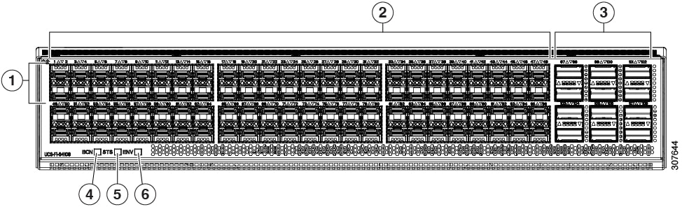
The following image shows the rear view of the Cisco UCS 64108 fabric interconnect, and includes the ports that support breakout port functionality:

Figure 1. Cisco UCS 64108 Fabric Interconnect Rear View

1

Ports 1-16. Unified Ports can operate as 10/25 Gbps Ethernet or 8/16/32 Gbps Fibre Channel. FC ports are converted in groups of four.

Unified ports:

  • 10/25 Gbps Ethernet or FCoE

  • 8/16/32 Gbps Fibre Channel

2

Ports 1-96. Each port can operate as either a 10 Gbps or 25 Gbps Ethernet or FCoE SFP28 port.

3

Uplink Ports 97-108. Each port can operate as either a 40 Gbps or 100 Gbps Ethernet or FCoE port. When using a breakout cable, each of these ports can operate as 4 x 10 Gbps or 4 x 25 Gbps Ethernet or FCoE ports.

Ports 97 - 108 can be used to connect to Ethernet or FCoE uplink ports, and not to UCS server ports.

4

Ports 89-96

  • 10/25 Gbps Ethernet or FCoE

  • 1 Gbps Ethernet

5

System environment (fan fault) LED

6

System status LED

7

Beacon LED

Breakout Port Guidelines

The following are the guidelines for breakout functionality for Cisco UCS 64108 fabric interconnects:

  • The breakout configurable ports are ports 97-108.

  • You cannot configure the speed for each breakout port. Each breakout port is in auto mode.

  • The fabric interconnect is rebooted after you configure the breakout mode for any of the supported fabric interconnect ports (1/97 to 1/108).

  • Breakout ports are not supported as destinations for traffic monitoring.

  • Ports 97-108 can be configured as uplink, appliance, server(using FEX), and FCoE storage ports.

Port Breakout Functionality on Cisco UCS 6454 Fabric Interconnects

About Breakout Ports

Cisco UCS 6454 fabric interconnects support splitting a single 40/100G QSFP port into four 10/25G ports using a supported breakout cable. These ports can be used only as uplink ports connecting to a 10/25G switch. On the UCS 6454 fabric interconnect, by default, there are 6 ports in the 40/100G mode. These are ports 49 to 54. These 40/100G ports are numbered in a 2-tuple naming convention. For example, the second 40G port is numbered as 1/50. The process of changing the configuration from 40G to 10 G, or from 100G to 25G is called breakout, and the process of changing the configuration from [4X]10G to 40G or from [4X]25G to 100G is called unconfigure.

When you break out a 40G port into 10G ports or a 100G port into 25G ports, the resulting ports are numbered using a 3-tuple naming convention. For example, the breakout ports of the second 40-Gigabit Ethernet port are numbered as 1/50/1, 1/50/2, 1/50/3, 1/50/4.

Starting with Cisco UCS Manager Release 4.1(3a), you can connect Cisco UCS Rack servers with VIC 1455 and 1457 adapters, to the uplink ports 49 to 54 (40/100 Gbps Ethernet or FCoE) in Cisco UCS 6454 Fabric Interconnects.


Note


Cisco UCS Manager does not support connection of FEX, chassis, blade, IOM, or adapters (other than VIC 1455 and 1457 adapters) to the uplink ports of Fabric Interconnect.


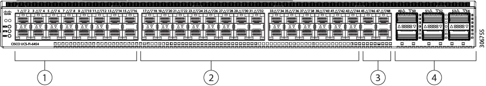
The following image shows the rear view of the Cisco UCS 6454 fabric interconnect, and includes the ports that support breakout port functionality:

Figure 2. Cisco UCS 6454 Fabric Interconnect Rear View

1

Ports 1-16 (Unified Ports 10/25 Gbps Ethernet or FCoE or 8/16/32 Gbps Fibre Channel)

2

Ports 17-44 (10/25 Gbps Ethernet or FCoE)

3

Ports 45-48 (1/10/25 Gbps Ethernet or FCoE)

4

Uplink Ports 49-54 (40/100 Gbps Ethernet or FCoE)

Breakout Port Guidelines

The following are the guidelines for breakout functionality for Cisco UCS 6454 fabric interconnects:

  • The breakout configurable ports are ports 49-54.

  • You cannot configure the speed for each breakout port. Each breakout port is in auto mode.

  • The fabric interconnect is rebooted after you configure the breakout mode for any of the supported fabric interconnect ports (1/49 to 1/54).

  • In Cisco UCS Manager Release 4.0(2), breakout ports are not supported as destinations for traffic monitoring.

  • Ports 49-54 can only be configured as uplink ports. They cannot be configured as any of the following:

    • Server ports

    • FCoE storage ports

    • Appliance ports

Port Breakout Functionality on Cisco UCS 6300 Series Fabric Interconnects

About Breakout Ports

Cisco UCS fabric interconnect 6300 series supports splitting a single QSFP port into four 10G ports using a supported breakout cable. By default, there are 32 ports in the 40G mode. These 40G ports are numbered in a 2-tuple naming convention. For example, the second 40G port is numbered as 1/2. The process of changing the configuration from 40G to 10G is called breakout and the process of changing the configuration from [4X]10G to 40G is called unconfigure.

When you break out a 40G port into 10G ports, the resulting ports are numbered using a 3-tuple naming convention. For example, the breakout ports of the second 40-Gigabit Ethernet port are numbered as 1/2/1, 1/2/2, 1/2/3, 1/2/4.

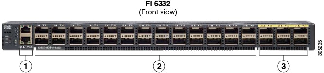
The following image shows the front view for the Cisco UCS 6332 series fabric interconnects, and includes the ports that may support breakout port functionality:

Figure 3. Cisco UCS 6332 Series Fabric Interconnects Front View

1

L1 and L2 high availability ports

2

28 X 40G QSFP ports ( 98 X 10G SFP ports)

Note

 
  • QSA module is required on ports 13–14

  • A QSFP to 4XSFP breakout cable is required for 10G support.

3

6 X 40G QSFP ports

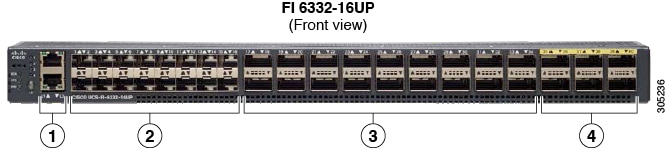
The following image shows the front view for the Cisco UCS 6332-16UP series fabric interconnects, and includes the ports that may support breakout port functionality:

Figure 4. Cisco UCS 6332-16UP Series Fabric Interconnects Front View

1

L1 and L2 high availability ports

2

16 X 1/10G SFP (16 X 4/8/16G FC ports)

3

18 X 40G QSFP(72 X 10G SFP+)

Note

 
  • A QSFP to 4XSFP breakout cable is required for 10G support.

4

6 X 40G QSFP ports

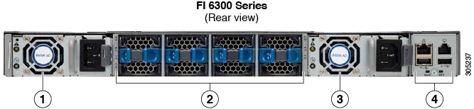
The following image shows the rear view of the Cisco UCS 6300 series fabric interconnects.

Figure 5. Cisco UCS 6300 Series Fabric Interconnects Rear View

1

Power supply

2

Four fans

3

Power supply

4

Serial ports

Breakout Port Constraints

The following table summarizes the constraints for breakout functionality for Cisco UCS 6300 series fabric interconnects:

Cisco UCS 6300 Series Fabric Interconnect Series

Breakout Configurable Ports

Ports without breakout functionality support

Cisco UCS 6332

1–12, 15–26

13–14, 27–32

Note

 
  • Auto-negotiate behavior is not supported on ports 27–32.

Cisco UCS 6332-16UP

17–34

1–16, 35–40

Note

 
  • Auto-negotiate behavior is not supported on ports 35–40


Important


Up to four breakout ports are allowed if QoS jumbo frames are used.


Configuring Multiple Breakout Ports

On a UCS 6300 Fabric Interconnect, you can specify a 40 Gigabit Ethernet port and create four 10 Gigabit Ethernet unconfigured breakout ports. On a UCS 6454 Fabric Interconnect, you can specify a 40 or 100 Gigabit Ethernet port and create four 10 or 25 Gigabit Ethernet unconfigured breakout ports. Because configuring breakout on a port causes the reboot of the Fabric Interconnect, we recommend that you breakout all required ports in a single transaction.

Before you begin

Before configuring a breakout port, view the port status using the show port command.

SUMMARY STEPS

  1. UCS-A # scope cabling
  2. UCS-A /cabling # scope fabric {a | b}
  3. UCS-A /cabling/fabric # create breakout slot-id port-id
  4. UCS-A /cabling/fabric/breakout* # set breakouttype {10g-4x | 25g-4x}
  5. UCS-A /cabling/fabric/breakout* # up
  6. UCS-A /cabling/fabric/breakout* # commit-buffer

DETAILED STEPS

  Command or Action Purpose

Step 1

UCS-A # scope cabling

Enters the cabling mode.

Step 2

UCS-A /cabling # scope fabric {a | b}

Enters cabling fabric mode for the specified fabric.

Step 3

UCS-A /cabling/fabric # create breakout slot-id port-id

Creates the breakout port on the selected slot and port.

Step 4

UCS-A /cabling/fabric/breakout* # set breakouttype {10g-4x | 25g-4x}

Specifies the type of breakout port on UCS 6454 and UCS 6536 Fabric Interconnects.

Step 5

UCS-A /cabling/fabric/breakout* # up

Returns you to fabric mode.

Repeat steps 3 and 5 for each breakout port on UCS 6300 Fabric Interconnect

Repeat steps 3, 4, and 5 for each breakout port on a UCS 6454.

Step 6

UCS-A /cabling/fabric/breakout* # commit-buffer

Commits the transaction to the server.

What to do next

Verify that you created breakout ports on the fabric interconnect and on the NXOS switch. On the fabric interconnect use the show breakout command in cabling fabric mode for the specified fabric. In NXOS, use the show interface brief command.

Configuring a Breakout Ethernet Uplink Port

SUMMARY STEPS

  1. UCS-A# scope eth-uplink
  2. UCS-A /eth-uplink # scope fabric{a | b}
  3. UCS-A /eth-uplink/fabric # create aggr-interface slot-numaggregate port-num
  4. UCS-A /eth-uplink/fabric/aggr-interface* # create br-interface breakout-port-num
  5. UCS-A /eth-uplink/fabric/aggr-interface/br-interface # commit-buffer

DETAILED STEPS

  Command or Action Purpose

Step 1

UCS-A# scope eth-uplink

Enters Ethernet uplink mode.

Step 2

UCS-A /eth-uplink # scope fabric{a | b}

Enters Ethernet uplink fabric mode for the specified fabric.

Step 3

UCS-A /eth-uplink/fabric # create aggr-interface slot-numaggregate port-num

Creates the interface for the specified aggregate (main) Ethernet uplink port.

Step 4

UCS-A /eth-uplink/fabric/aggr-interface* # create br-interface breakout-port-num

Creates an interface for the specified breakout Ethernet uplink port.

Step 5

UCS-A /eth-uplink/fabric/aggr-interface/br-interface # commit-buffer

Commits the transaction to the server.

Example

The following example shows how to create an interface for breakout Ethernet uplink port 1 of the aggregate port 21 on slot 1 of fabric A:


UCS-A# scope eth-uplink 
UCS-A /eth-uplink # scope fabric a
UCS-A /eth-uplink/fabric # enter aggr-interface 1 21
UCS-A /eth-uplink/fabric/aggr-interface # create br-interface 1
UCS-A /eth-uplink/fabric/aggr-interface/br-interface*# commit-buffer

The following example shows how to create interfaces for breakout Ethernet uplink ports 1-4 of the aggregate port 49 on slot 1 of fabric A on a UCS 6454 fabric interconnect, and commit the transaction:

UCS-A# scope eth-uplink
UCS-A /eth-uplink # scope fabric a 
UCS-A /eth-uplink/fabric # create aggr-interface 1 49
UCS-A /eth-uplink/fabric/aggr-interface* # create br-interface 1
UCS-A /eth-uplink/fabric/aggr-interface/br-interface* # up
UCS-A /eth-uplink/fabric/aggr-interface* # create br-interface 2
UCS-A /eth-uplink/fabric/aggr-interface/br-interface* # up
UCS-A /eth-uplink/fabric/aggr-interface* # create br-interface 3
UCS-A /eth-uplink/fabric/aggr-interface/br-interface* # up
UCS-A /eth-uplink/fabric/aggr-interface* # create br-interface 4
UCS-A /eth-uplink/fabric/aggr-interface/br-interface* # up
UCS-A /eth-uplink/fabric/aggr-interface* # commit-buffer
UCS-A /eth-uplink/fabric/aggr-interface # 

The following example shows the breakout configuration for ports 1/49/1 to 1/49/4 of fabric A on a UCS 6454 fabric interconnect:

UCS-A# scope fabric-interconnect a 
UCS-A /fabric-interconnect # show port
Ether Port: 
Slot  Aggr       Port  Port Oper State  Mac                  Role    Xcvr 
----- ---------- ----- ---------------- -------------------- ------- ---- 
1     49         1     Sfp Not Present  8C:60:4F:BC:C4:D4    Unknown N/A 
1     49         2     Sfp Not Present  8C:60:4F:BC:C4:D5    Unknown N/A 
1     49         3     Sfp Not Present  8C:60:4F:BC:C4:D6    Unknown N/A 
1     49         4     Sfp Not Present  8C:60:4F:BC:C4:D7    Unknown N/A 

Configuring a Breakout Ethernet Uplink Port Channel Member

SUMMARY STEPS

  1. UCS-A# scope eth-uplink
  2. UCS-A# /eth-uplink # scope fabric{a | b}
  3. UCS-A# /eth-uplink/fabric # scope fcoe-port-channel fcoe-port-channel
  4. UCS-A /eth-uplink/fabric/port-channe/fcoe-port-channel # enter aggr-interface slot-id port-id
  5. UCS-A /eth-uplink/fabric/port-channel/member-aggr-port # create br-member-portbreakout-port-num
  6. UCS-A /eth-uplink/fabric/port-channel/member-aggr-port/br-member-port # commit-buffer

DETAILED STEPS

  Command or Action Purpose

Step 1

UCS-A# scope eth-uplink

Enters Ethernet uplink mode.

Step 2

UCS-A# /eth-uplink # scope fabric{a | b}

Enters Ethernet uplink mode for the specified fabric.

Step 3

UCS-A# /eth-uplink/fabric # scope fcoe-port-channel fcoe-port-channel

Enters port channel for the specified FCoE uplink port.

Step 4

UCS-A /eth-uplink/fabric/port-channe/fcoe-port-channel # enter aggr-interface slot-id port-id

Enters the interface for the specified aggregate(main) FCoE uplink port.

Step 5

UCS-A /eth-uplink/fabric/port-channel/member-aggr-port # create br-member-portbreakout-port-num

Creates the FCoE uplink port channel member.

Step 6

UCS-A /eth-uplink/fabric/port-channel/member-aggr-port/br-member-port # commit-buffer

Example:

The following example creates an Ethernet uplink port channel member for an Ethernet port on port 2, and commits the transaction:
UCS-A# scope eth-storage 
UCS-A /eth-uplink # scope fabric a
UCS-A /eth-uplink/fabric # scope fcoe-port-channel 51
UCS-A /eth-uplink/fabric/port-channel/member-aggr-port # create br-member-port 2
UCS-A /eth-uplink/fabric/port-channel/member-aggr-port/br-member-port* # commit-buffer

Commits the transaction to the server.

Configuring Ethernet Uplink Breakout Port as a Pin Group Target

SUMMARY STEPS

  1. UCS-A# scope eth-uplink
  2. UCS-A# /eth-uplink/pin-group # enter pin-group pin-group-name
  3. UCS-A# /et h-uplink/pin-group # set target{a|b} breakout-portslot-numaggregate-port-numbreakout-port-num
  4. UCS-A # /eth-uplink/pin-group # commit-buffer

DETAILED STEPS

  Command or Action Purpose

Step 1

UCS-A# scope eth-uplink

Enters Ethernet uplink mode.

Step 2

UCS-A# /eth-uplink/pin-group # enter pin-group pin-group-name

Enters the pin group with the specified name.

Step 3

UCS-A# /et h-uplink/pin-group # set target{a|b} breakout-portslot-numaggregate-port-numbreakout-port-num

Sets the selected target as the breakout port.

Step 4

UCS-A # /eth-uplink/pin-group # commit-buffer

Example:

The following example sets the pin group target to breakout port 2 of the aggregate port 1 on slot 1, on fabric A , and commits the transaction:

UCS-A# scope eth-uplink 
UCS-A /eth-uplink # enter pin-group test
UCS-A /eth-uplink/pin-group # set target a breakout-port 1 1 2
UCS-A /eth-uplink/pin-group* # commit-buffer 
 

Commits the transaction to the server.

Configuring Breakout Appliance Ports

You can follow the below steps to configure appliance breakout ports for both , and Cisco UCS 6400 Series Fabric Interconnect:

SUMMARY STEPS

  1. UCS-A# scope eth-storage
  2. UCS-A# /eth-storage # scope fabric{a | b}
  3. UCS-A# /eth-storage/fabric # enter aggr-interface slot-numaggregate-port-num
  4. UCS-A# /eth-storage/fabric/port-channel/member-aggr-port # create br -interfacebreakout-port-num
  5. UCS-A# /eth-storage/fabric/port-channel/member-aggr-port/br-member-port # commit-buffer

DETAILED STEPS

  Command or Action Purpose

Step 1

UCS-A# scope eth-storage

Enters Ethernet storage mode.

Step 2

UCS-A# /eth-storage # scope fabric{a | b}

Enters Ethernet storage mode for the specified fabric.

Step 3

UCS-A# /eth-storage/fabric # enter aggr-interface slot-numaggregate-port-num

Enters the interface for the specified aggregate(main) appliance port.

Step 4

UCS-A# /eth-storage/fabric/port-channel/member-aggr-port # create br -interfacebreakout-port-num

Creates an interface for the specified breakout appliance port.

Step 5

UCS-A# /eth-storage/fabric/port-channel/member-aggr-port/br-member-port # commit-buffer

Example:

The following example creates an interface for an appliance port 1 of the aggregate port 20 on slot 1 of fabric B, and commits the transaction:

UCS-A# scope eth-storage 
UCS-A /eth-storage # scope fabric a 
UCS-A /eth-storage/fabric # enter aggr-interface 1 20
UCS-A /eth-storage/fabric/aggr-interface # create br-interface 1
UCS-A /eth-storage/fabric/aggr-interface/br-interface* # commit-buffer 


Example:

Note


If the port is only connected to 100G SFP which is broken out in 25x4 breakout port then when creating an appliance port, the default speed for a breakout port would be Auto.

Commits the transaction to the server.

Configuring a Breakout Appliance Port Channel Member

SUMMARY STEPS

  1. UCS-A# scope eth-storage
  2. UCS-A# /eth-storage # scope fabric{a | b}
  3. UCS-A# /eth-storage # scope port-channelport-channel-num
  4. UCS-A# /eth-storage/fabric # enter aggr-interface slot-numaggregate-port-num
  5. UCS-A /eth-storage/fabric/port-channel # enter member-aggr-port slot-id port-id
  6. UCS-A /eth-storage/fabric/port-channel/member-aggr-port # create br-member-portbreakout-port-num
  7. UCS-A /eth-storage/fabric/port-channel/member-aggr-port/br-member-port # commit-buffer

DETAILED STEPS

  Command or Action Purpose

Step 1

UCS-A# scope eth-storage

Enters Ethernet storage mode.

Step 2

UCS-A# /eth-storage # scope fabric{a | b}

Enters Ethernet storage mode for the specified fabric.

Step 3

UCS-A# /eth-storage # scope port-channelport-channel-num

Enters Ethernet storage mode for the specified port-channel.

Step 4

UCS-A# /eth-storage/fabric # enter aggr-interface slot-numaggregate-port-num

Enters the interface for the specified aggregate(main) appliance port.

Step 5

UCS-A /eth-storage/fabric/port-channel # enter member-aggr-port slot-id port-id

Enters the appliance port channel member port.

Step 6

UCS-A /eth-storage/fabric/port-channel/member-aggr-port # create br-member-portbreakout-port-num

Creates the appliance port channel member.

Step 7

UCS-A /eth-storage/fabric/port-channel/member-aggr-port/br-member-port # commit-buffer

Example:

The following example creates an appliance port channel member for an appliance port 2, and commits the transaction:
UCS-A# scope eth-storage 
UCS-A /eth-storage # scope fabric a
UCS-A /eth-storage/fabric # scope port-channel 21
UCS-A /eth-storage/fabric/port-channel # enter member-aggr-port 1 2
UCS-A /eth-storage/fabric/port-channel/member-aggr-port # create br-member-port 2
UCS-A /eth-storage/fabric/port-channel/member-aggr-port/br-member-port* # commit-buffer 

Commits the transaction to the server.

Configuring Breakout FCoE Storage Ports

SUMMARY STEPS

  1. UCS-A# scope fc-storage
  2. UCS-A# /fc-storage scope fabric{a | b
  3. UCS-A# /fc-storage/fabric enter aggr-interface slot-numaggregate port-num
  4. UCS-A# /fc-storage/fabric/aggr-interface # create br-interface br-fcoe breakout-port-num
  5. UCS-A# /fc-storage/fabric/aggr-interface/br-interface/br-fcoe # commit-buffer

DETAILED STEPS

  Command or Action Purpose

Step 1

UCS-A# scope fc-storage

Enters Fibre Channel storage mode.

Step 2

UCS-A# /fc-storage scope fabric{a | b

Enters Fibre Channel storage mode for the specified fabric.

Step 3

UCS-A# /fc-storage/fabric enter aggr-interface slot-numaggregate port-num

Enter the interface for the specified aggregate(main) Fibre Channel storage port.

Step 4

UCS-A# /fc-storage/fabric/aggr-interface # create br-interface br-fcoe breakout-port-num

Creates an interface for the specified breakout Fibre Channel storage port.

Step 5

UCS-A# /fc-storage/fabric/aggr-interface/br-interface/br-fcoe # commit-buffer

Example:

The following example creates an interface for a breakout Fibre Channel storage port 1 of the aggregate port 21 on slot 1 of fabric a, and commits the transaction:

UCS-A# scope fc-storage
UCS-A /fc-storage # scope fabric a
UCS-A /fc-storage/fabric # enter aggr-interface 1 21
UCS-A /fc-storage/fabric/aggr-interface # create br-interface 1
UCS-A /eth-uplink/fabric/aggr-interface/br-interface/br-fcoe  # commit-buffer

Commits the transaction to the server.

Configuring a Breakout FCoE Uplink Port

SUMMARY STEPS

  1. UCS-A# scope fc-uplink
  2. UCS-A# /fc-uplink scope fabric{a | b
  3. UCS-A# /fc-uplink/fabric enter aggr-interface slot-numaggregate port-num
  4. UCS-A# /fc-uplink/fabric/aggr-interface # create br-fcoeinterface breakout-port-num
  5. UCS-A# /fc-uplink/fabric/aggr-interface/ br-fcoeinterface # commit-buffer

DETAILED STEPS

  Command or Action Purpose

Step 1

UCS-A# scope fc-uplink

Enters FC Uplink mode.

Step 2

UCS-A# /fc-uplink scope fabric{a | b

Enters FC - Uplink mode for the specific fabric.

Step 3

UCS-A# /fc-uplink/fabric enter aggr-interface slot-numaggregate port-num

Enters interface for the specified aggregate(main) FCoE uplink port.

Step 4

UCS-A# /fc-uplink/fabric/aggr-interface # create br-fcoeinterface breakout-port-num

Creates an interface for the specified breakout FCoE uplink port.

Step 5

UCS-A# /fc-uplink/fabric/aggr-interface/ br-fcoeinterface # commit-buffer

Example:

The following example shows how to create an interface for breakout FCoE uplink port 1 of the aggregate port 20 on slot 1 of fabric A:

UCS-A# scope eth-uplink 
UCS-A /fc-uplink # scope fabric a
UCS-A /fc-uplink/fabric # enter aggr-interface 1 20
UCS-A /fc-uplink/fabric/aggr-interface # create br-fcoeinterface 1
UCS-A /fc-uplink/fabric/aggr-interface/br-fcoeinterface # commit-buffer

Commits the transaction to the server.

Configuring an FCoE Port Channel Member

SUMMARY STEPS

  1. UCS-A# scope fc-uplink
  2. UCS-A# /fc-uplink # scope fabric{a | b}
  3. UCS-A# /fc-uplink/fabric # scope fcoe-port-channel fcoe-port-num
  4. UCS-A /fc-uplink/fabric/port-channel # enter aggr-interface slot-num port-numaggregate-port-num
  5. UCS-A /fc-uplink/fabric/port-channel/member-aggr-port # create br-member-portbreakout-port-num
  6. UCS-A /fc-uplink/fabric/port-channel/member-aggr-port/br-member-port # commit-buffer

DETAILED STEPS

  Command or Action Purpose

Step 1

UCS-A# scope fc-uplink

Enters Ethernet storage mode.

Step 2

UCS-A# /fc-uplink # scope fabric{a | b}

Step 3

UCS-A# /fc-uplink/fabric # scope fcoe-port-channel fcoe-port-num

Step 4

UCS-A /fc-uplink/fabric/port-channel # enter aggr-interface slot-num port-numaggregate-port-num

Enters the FCoE port channel member port.

Step 5

UCS-A /fc-uplink/fabric/port-channel/member-aggr-port # create br-member-portbreakout-port-num

Creates the FCoE port channel member for the specified breakout port.

Step 6

UCS-A /fc-uplink/fabric/port-channel/member-aggr-port/br-member-port # commit-buffer

Example:

The following example creates a breakout FCoE port channel member port 4 on aggregate port 21, and commits the transaction:
UCS-A# scope eth-storage 
UCS-A /fc-uplink # scope fabric a
UCS-A /fc-uplink/fabric # scope port-channel 51
UCS-A /fc-uplink/fabric/port-channel # enter member-aggr-port 1 21
UCS-A /fc-uplink/fabric/port-channel/member-aggr-port # create br-member-port 4
UCS-A /fc-uplink/fabric/port-channel/member-aggr-port/br-member-port* # commit-buffer 

Commits the transaction to the server.

Configuring a Breakout VLAN Member Port

SUMMARY STEPS

  1. USA-A# scope eth-uplink
  2. USA-A /eth-uplink # scope vlan id
  3. USA-A /eth-uplink/vlan # enter member-aggr-port {a|b} slot-id port id
  4. USA-A /eth-uplink/vlan/member-aggr-port # create br-member-port breakout-port-name
  5. USA-A /eth-uplink/vlan/member-aggr-port/br-member-port # commit-buffer

DETAILED STEPS

  Command or Action Purpose

Step 1

USA-A# scope eth-uplink

Enters Ethernet uplink mode for the specified fabric.

Step 2

USA-A /eth-uplink # scope vlan id

Enters VLAN mode.

Step 3

USA-A /eth-uplink/vlan # enter member-aggr-port {a|b} slot-id port id

Enters an interface for the specified fabric, main aggregate port, and subport. breakout VLAN member port.

Step 4

USA-A /eth-uplink/vlan/member-aggr-port # create br-member-port breakout-port-name

Creates an interface for the specified breakout VLAN member port.

Step 5

USA-A /eth-uplink/vlan/member-aggr-port/br-member-port # commit-buffer

Example:

The following example creates an interface for a VLAN member on the aggregate port 4 on slot 1 of breakout Ethernet uplink port 1, and commits the transaction:
USA-A# scope eth-uplink 
USA-A /eth-uplink # scope vlan id
USA-A /eth-uplink/vlan # enter member-aggr-port a 1 1
USA-A /eth-uplink/vlan/member-aggr-port* # create br-member-port 4
USA-A /eth-uplink/vlan/member-aggr-port/br-member-port* # commit-buffer  
 

Commits the transaction to the server.

What to do next

Verify that you created the breakout VLAN Member port using the show command.

Modifying a Breakout Port

The following table describes how to modify the supported breakout ports.

Breakout Port Type

Scope

CLI Location From Which To Modify

Modify Options

Ethernet Uplink

eth-uplink

UCS-A eth-uplink/fabric/aggr-interface/br-interface # create

mon-src — Creates a monitor source session.

UCS-A /eth-uplink/fabric/aggr-interface/br-interface # set

eth-link-profile — Sets the Ethernet Link profile name.

flow-control-policy — Sets the flow control policy that configures the receive and send flow control parameters for the LAN and Ethernet uplink ports.

speed — Sets the speed for an Ethernet uplink port.

user-label — Assigns an identifying label to the Ethernet Uplink port.

UCS-A /eth-uplink/fabric/aggr-interface/br-interface #

disable — Disables the aggregate interface for the Ethernet Uplink breakout port.

enable — Enables the aggregate interface for the Ethernet Uplink breakout port.

Ethernet Uplink port-channel member

fc-storage

UCS-A /eth-uplink/fabric/port-channel/aggr-interface/br-member-port # set

eth-link-profile — Sets the Ethernet Link profile name.

UCS-A /eth-uplink/fabric/port-channel/aggr-interface/br-member-port #

disable — Disables the aggregate interface for the breakout Ethernet Uplink port-channel member.

enable — Enables the aggregate interface for the breakout Ethernet Uplink port-channel member.

FCoE Uplink

fc-uplink

UCS-A /fc-uplink/fabric/aggr-interface/br-fcoeinterface # create

mon-src — Creates a monitor source session.

UCS-A /fc-uplink/fabric/aggr-interface/br-fcoeinterface # set

eth-link-profile — Sets the Ethernet Link profile name.

user-label — Assigns an identifying label to the FCoE uplink breakout port.

UCS-A /fc-uplink/fabric/aggr-interface/br-fcoeinterface #

disable —Disables the aggregate interface for the FCoE uplink breakout port.

enable — Enables the aggregate interface for the FCoE uplink breakout port.

FCoE Uplink port-channel member

eth-uplink

UCS-A /fc-uplink/fabric/fcoe-port-channel/aggr-interface/br-member-port # set

eth-link-profile — Sets the Ethernet Link profile name.

A /fc-uplink/fabric/fcoe-port-channel/aggr-interface/br-member-port #

disable — Disables the aggregate interface for the breakout FCoE uplink port-channel member.

enable — Enables the aggregate interface for the breakout FCoE uplink port-channel member.

FCoE Storage port

fc-storage

UCS-A fc-storage/fabric/aggr-interface/br-fcoe # create

mon-src — Creates a monitor source session.

UCS-A /fc-storage/fabric/aggr-interface/br-fcoe # set

user-label — Assigns an identifying label to the server.

UCS-A /fc-storage/fabric/aggr-interface/br-fcoe #

disable — Disables the aggregate interface for the breakout FCoE Storage port

enable — Enables the aggregate interface for the breakout FCoE Storage port.

Appliance Port

eth-storage

UCS-A /eth-storage/fabric/aggr-interface/br-interface # set

adminspeed — Sets the speed for a fabric interface.

flowctrlpolicy —Sets the flow control policy that configures the receive and send flow control parameters for the appliance ports.

nw-control-policy — Creates a network control policy for the appliance port.

pingroupname — Sets the pin group name for the fabric interface.

portmode — Sets the appliance port mode.

prio — Sets the QoS (Quality of Service) priority level.

user-label — Assigns an identifying label to the appliance port.

UCS-A /eth-storage/fabric/aggr-interface/br-interface # create

eth-target — Creates the Ethernet target endpoint.

mon-src — Creates a monitor source session.

UCS-A /eth-storage/fabric/aggr-interface/br-interface #

disable — Disables the aggregate interface for the appliance breakout port.

enable —Enables the aggregate interface for the appliance breakout port.

Appliance port-channel member

eth-storage

UCS-A /eth-storage/fabric/port-channel/member-aggr-port #

disable — Disables the aggregate interface for the breakout appliance port-channel member.

enable —Enables the aggregate interface for the breakout appliance port-channel member.

VLAN Member

eth-uplink

A /eth-uplink/vlan/member-aggr-port/br-member-port # set

isnative — Marks a member-port as a native VLAN.

Pin Group - Pin Target

eth-uplink

N/A

N/A

SPAN (Traffic Monitoring) Destination Port

eth-traffic-mon

A /eth-traffic-mon/fabric/eth-mon-session/dest-aggr-interface/br-dest-interface # set

speed — Sets the speed for the SPAN (Traffic Monitoring) destination port.

SUMMARY STEPS

  1. UCS-A# scope eth-uplink .
  2. UCS-A /eth-uplink # scope fabric {a | b} .
  3. UCS-A /eth-uplink/fabric # scope aggr-interface port-number port-id .
  4. UCS-A /eth-uplink/fabric/aggr-interface # scope br-interface port-id .
  5. UCS-A /eth-uplink/fabric/aggr-interface/br-interface # create mon-src .

DETAILED STEPS

  Command or Action Purpose

Step 1

UCS-A# scope eth-uplink .

Enters Ethernet uplink mode.

Step 2

UCS-A /eth-uplink # scope fabric {a | b} .

Enters Ethernet uplink fabric mode for the specified fabric.

Step 3

UCS-A /eth-uplink/fabric # scope aggr-interface port-number port-id .

Enters the interface for the specified aggregate(main) Ethernet uplink port.

Step 4

UCS-A /eth-uplink/fabric/aggr-interface # scope br-interface port-id .

Enters the breakout Ethernet port for the specified port number.

Step 5

UCS-A /eth-uplink/fabric/aggr-interface/br-interface # create mon-src .

Example:

The following example shows how to modify a Ethernet uplink port as a monitor source in breakout port 1 of the aggregate (main) interface in port 1 with an ID of 21.
UCS-A# scope eth-uplink
UCS-A /eth-uplink # scope fabric a
UCS-A /eth-uplink/fabric # scope aggr-interface 1 21
UCS-A /eth-uplink/fabric/aggr-interface # scope br-interface 1
UCS-A /eth-uplink/fabric/aggr-interface/br-interface # create   
	UCS-A /eth-uplink/fabric/aggr-interface/br-interface # create mon-src

Modifies the interface as a monitoring source.

Modifying the Breakout Ethernet Uplink Port Speed and User Label

pranspat-3gfi-A /eth-uplink/fabric/aggr-interface/br-interface # set      
	eth-link-profile     Ethernet Link Profile name   
	flow-control-policy  flow control policy   
	speed                 Speed   
	user-label           User Label 
pranspat-3gfi-A /eth-uplink/fabric/aggr-interface/br-interface # 
	disable      Disables services   
	enable       Enables services

Un-configuring Breakout Ports

If you have a breakout on port 2 in slot 1, you can un-configure the breakout port.

Before you begin

You can use the show port command to list the ports for the Fabric Interconnect (FI), and select the port that you want to breakout.

SUMMARY STEPS

  1. UCS-A# / fabric-interconnect # show port
  2. UCS-A# scope cabling
  3. UCS-A# /cabling # scope fabric {a | b }
  4. UCS-A #/ cabling # delete breakout {1 | 2
  5. UCS-A /cabling/fabric/breakout* # commit .

DETAILED STEPS

  Command or Action Purpose

Step 1

UCS-A# / fabric-interconnect # show port

Example:

The following example lists the ports.
Slot  Aggr Port  Port  Oper State       Mac                  Role    Xcvr
----- ---------- ----- ---------------- -------------------- ------- ----
    1          0     1 Link Down        84:B8:02:CA:37:56    Network 1000base T
    1          2     1 Sfp Not Present  84:B8:02:CA:37:57    Unknown N/A
    1          2     2 Sfp Not Present  84:B8:02:CA:37:57    Unknown N/A
    1          2     3 Sfp Not Present  84:B8:02:CA:37:57    Unknown N/A
    1          2     4 Sfp Not Present  84:B8:02:CA:37:57    Unknown N/A
    1          0     3 Sfp Not Present  84:B8:02:CA:37:58    Unknown N/A

Displays the ports for the Fabric Interconnect.

Step 2

UCS-A# scope cabling

Enters the cabling mode.

Step 3

UCS-A# /cabling # scope fabric {a | b }

Specifies fabric a or b.

Step 4

UCS-A #/ cabling # delete breakout {1 | 2

Step 5

UCS-A /cabling/fabric/breakout* # commit .

Commits the transaction to the system configuration.

What to do next

You can use the show port to view the unconfigured breakouts ports.

Deleting Breakout Ports

You can delete 10 Gig Ethernet breakout ports. Use the br-interface or br-member-port scopes to select breakout sub-ports 1-4. You must provide the sub-port id for this scope. For example, scope br-interface sub_port_id .

The example described in this topic describes how to delete a breakout Ethernet uplink port. The following table describes how to delete the supported Ethernet breakout ports.

Breakout Port Type

Scope

CLI Location From Which To Delete

Ethernet Uplink

eth-uplink

UCS-A /eth-uplink/fabric/aggr-interface # delete br-interface number

Ethernet Uplink port-channel member

eth-uplink

UCS-A /eth-uplink/fabric/port-channel/aggr-interface # delete br-member-port number

FCoE Uplink

fc-uplink

UCS-A /fc-uplink/fabric/aggr-interface # delete br-fcoeinterface number

FCoE Uplink port-channel member

eth-uplink

UCS-A /fc-uplink/fabric/fcoe-port-channel/aggr-interface # delete br-member-port number

FCoE Storage port

fc-storage

UCS-A /fc-storage/fabric/aggr-interface # delete br-interface br-fcoe number

Appliance Port

eth-storage

UCS--A /eth-storage/fabric/port-channel/member-aggr-port # delete br-member-port number

Appliance port-channel member

eth-storage

UCS-A /eth-storage/fabric/aggr-interface # delete br-interface number

VLAN Member

eth-uplink

UCS-A /eth-uplink/vlan/member-aggr-port # delete br-member-port number

Pin Group - Pin Target

eth-uplink

UCS-A /eth-uplink/pin-group # delete target number

SPAN (Traffic Monitoring) Destination Port

eth-traffic-mon

UCS-A /eth-traffic-mon/fabric/eth-mon-session/dest-aggr-interface # delete br-dest-interface

SUMMARY STEPS

  1. UCS-A# scope eth-uplink
  2. UCS-A# /eth-storage # scope fabric{a | b}
  3. UCS-A /eth-uplink/fabric # scope port-channel number
  4. UCS-A /eth-uplink/fabric/port-channel/aggr-interface # delete br-member-port number
  5. UCS-A /eth-uplink/fabric/port-channel/aggr-interface # commit-buffer

DETAILED STEPS

  Command or Action Purpose

Step 1

UCS-A# scope eth-uplink

Enters the Ethernet uplink mode.

Step 2

UCS-A# /eth-storage # scope fabric{a | b}

Enters Ethernet storage mode for the specified fabric.

Step 3

UCS-A /eth-uplink/fabric # scope port-channel number

Enters Ethernet uplink fabric port channel mode for the specified port channel.

Step 4

UCS-A /eth-uplink/fabric/port-channel/aggr-interface # delete br-member-port number

Deletes the specified breakout port.

Step 5

UCS-A /eth-uplink/fabric/port-channel/aggr-interface # commit-buffer

Example:

This example deletes an Ethernet Uplink port-channel member in breakout port 1 of the aggregate (main) interface port 1 slot 1.
UCS-A# scope eth-uplink 
UCS-A /eth-uplink # scope fabric a
UCS-A /eth-uplink/fabric # scope port-channel 1
UCS-A /eth-uplink/fabric/port-channel # enter aggr-interface 1 1
UCS-A /eth-uplink/fabric/port-channel/aggr-interface # delete br-member-port 1
UCS-A /eth-uplink/fabric/port-channel/aggr-interface* # commit-buffer

Commits the transaction to the server.

What to do next

Verify that you deleted the specified breakout port using the show command.

Cisco UCS Mini Scalability Ports

The Cisco UCS 6324 Fabric Interconnect contains a scalability port as well as four unified ports. The scalability port is a 40GB QSFP+ breakout port that, with proper cabling, can support four 1G or 10G SFP+ ports. The scalability ports can be used as a licensed server port for supported Cisco UCS rack servers, an appliance port, or a FCoE port.

In the Cisco UCS Manager GUI, the scalability port is displayed as Scalability Port 5 below the Ethernet Ports node. The individual breakout ports are displayed as Port 1 through Port 4.

In the Cisco UCS Manager CLI, the scalability port is not displayed, but the individual breakout ports are displayed as Br-Eth1/5/1 through Br-Eth1/5/4 .

Configuring Scalability Ports

To configure ports, port channel members or SPAN members on the scalability port, scope into the scalability port first, then follow the steps for a standard unified port.

SUMMARY STEPS

  1. UCS-A# scope eth-server
  2. UCS-A /eth-server # scope fabric {a | b}
  3. UCS-A /eth-server/fabric # scope aggr-interface slot-num port-num
  4. UCS-A /eth-server/fabric/aggr-interface # show interface
  5. UCS-A /eth-server/fabric/aggr-interface # create interface slot-num port-num
  6. UCS-A /eth-server/fabric/aggr-interface # commit-buffer

DETAILED STEPS

  Command or Action Purpose

Step 1

UCS-A# scope eth-server

Enters Ethernet server mode.

Step 2

UCS-A /eth-server # scope fabric {a | b}

Enters Ethernet server fabric mode for the specified fabric.

Step 3

UCS-A /eth-server/fabric # scope aggr-interface slot-num port-num

Enters ethernet server fabric aggregate interface mode for the scalability port.

Step 4

UCS-A /eth-server/fabric/aggr-interface # show interface

Displays the interfaces on the scalability port.

Step 5

UCS-A /eth-server/fabric/aggr-interface # create interface slot-num port-num

Creates an interface for the specified Ethernet server port.

Step 6

UCS-A /eth-server/fabric/aggr-interface # commit-buffer

Commits the transaction to the system configuration.

Example

The following example shows how to create an interface for Ethernet server port 3 on the fabric A scalability port and commit the transaction:

UCS-A# scope eth-server
UCS-A /eth-server # scope fabric a
UCS-A /eth-server/fabric # scope aggr-interface 1 5
UCS-A /eth-server/fabric/aggr-interface # show interface
Interface:

Slot Id Aggr-Port ID Port Id  Admin State Oper State    State Reason
------- ------------ -------- ----------- ------------- ------------
      1            5        1 Enabled     Up
      1            5        2 Enabled     Up     
      1            5        3 Enabled     Admin Down    Administratively Down
      1            5        4 Enabled     Admin Down    Administratively Down

UCS-A /eth-server/fabric/aggr-interface # create interface 1 3
UCS-A /eth-server/fabric/aggr-interface* # commit-buffer
UCS-A /eth-server/fabric/aggr-interface # 

Beacon LEDs for Unified Ports

Each port on the 6200 series fabric interconnect has a corresponding beacon LED. When the Beacon LED property is configured, the beacon LEDs illuminate, showing you which ports are configured in a given port mode.

You can configure the Beacon LED property to show you which ports are grouped in one port mode: either Ethernet or Fibre Channel. By default, the Beacon LED property is set to Off.


Note


For unified ports on the expansion module, you can reset the Beacon LED property to the default value of Off during expansion module reboot.


Configuring the Beacon LEDs for Unified Ports

Complete the following task for each module for which you want to configure beacon LEDs.

SUMMARY STEPS

  1. UCS-A# scope fabric-interconnect {a | b}
  2. UCS-A /fabric # scope card slot-id
  3. UCS-A /fabric/card # scope beacon-led
  4. UCS-A /fabric/card/beacon-led # set admin-state {eth | fc | off}
  5. UCS-A /fabric/card/beacon-led # commit-buffer

DETAILED STEPS

  Command or Action Purpose

Step 1

UCS-A# scope fabric-interconnect {a | b}

Enters fabric interconnect mode for the specified fabric.

Step 2

UCS-A /fabric # scope card slot-id

Enters card mode for the specified fixed or expansion module.

Step 3

UCS-A /fabric/card # scope beacon-led

Enters beacon LED mode.

Step 4

UCS-A /fabric/card/beacon-led # set admin-state {eth | fc | off}

Specifies which port mode is represented by illuminated beacon LED lights.

eth

All of the Unified Ports configured in Ethernet mode illuminate.

fc

All of the Unified Ports configured in Fibre Channel mode illuminate.

off

Beacon LED lights for all ports on the module are turned off.

Step 5

UCS-A /fabric/card/beacon-led # commit-buffer

Commits the transaction to the system configuration.

Example

The following example illuminates all of the beacon lights for Unified Ports in Ethernet port mode and commits the transaction:

UCS-A# scope fabric-interconnect a
UCS-A /fabric # scope card 1
UCS-A /fabric/card # scope beacon-led
UCS-A /fabric/card/beacon-led # set admin-state eth
UCS-A /fabric/card/beacon-led* # commit-buffer
UCS-A /fabric/card/beacon-led #

Physical and Backplane Ports

Displaying VIF Port Statistics Obtained From the Adaptor

SUMMARY STEPS

  1. UCS-A /fabric-interconnect # connect nxos {a | b}
  2. UCS-A(nxos)# show interface vethernet veth-id counters

DETAILED STEPS

  Command or Action Purpose

Step 1

UCS-A /fabric-interconnect # connect nxos {a | b}

Enters NX-OS mode for the fabric interconnect.

Step 2

UCS-A(nxos)# show interface vethernet veth-id counters

Displays VIF port statistics that are obtained from the adaptor.

Example

The following example shows how to display VIF port statistics that are obtained from the adaptor:


UCS-A /fabric-interconnect # connect nxos a
UCS-A(nxos)# show interface vethernet 684 counters

--------------------------------------------------------------------------------
Port                                 InOctets                      InUcastPkts
--------------------------------------------------------------------------------
Veth684                                    0                                 0

--------------------------------------------------------------------------------
Port                              InMcastPkts                      InBcastPkts
--------------------------------------------------------------------------------
Veth684                                    0                                 0

--------------------------------------------------------------------------------
Port                                OutOctets                     OutUcastPkts
--------------------------------------------------------------------------------
Veth684                                    0                                 0

--------------------------------------------------------------------------------
Port                             OutMcastPkts                     OutBcastPkts
--------------------------------------------------------------------------------
Veth684                                    0                                 0


Displaying VIF Port Statistics Obtained From the ASIC

SUMMARY STEPS

  1. UCS-A /fabric-interconnect # connect nxos {a | b}
  2. UCS-A(nxos)# show platform fwm info lif vethernet veth-id | grep frame

DETAILED STEPS

  Command or Action Purpose

Step 1

UCS-A /fabric-interconnect # connect nxos {a | b}

Enters NX-OS mode for the fabric interconnect.

Step 2

UCS-A(nxos)# show platform fwm info lif vethernet veth-id | grep frame

Displays VIF-port RX and TX frame statistics obtained from the ASIC.

RX statistics are for all type of frames. Tx statistics are only for known unicast frames.

Example

The following example shows how to display VIF-port RX and TX frame statistics obtained from the ASIC:


UCS-A /fabric-interconnect # connect nxos a
UCS-A(nxos)# show platform fwm info lif vethernet 684 | grep frame

vif29 pd: rx frames: 0 tx frames: 0;

UCS-A(nxos)# 


Displaying VIF Ports That Correspond to NIV Ports

SUMMARY STEPS

  1. UCS-A /fabric-interconnect # connect nxos {a | b}
  2. UCS-A(nxos)# show platform fwm info lif vethernet veth-id | grep niv

DETAILED STEPS

  Command or Action Purpose

Step 1

UCS-A /fabric-interconnect # connect nxos {a | b}

Enters NX-OS mode for the fabric interconnect.

Step 2

UCS-A(nxos)# show platform fwm info lif vethernet veth-id | grep niv

Displays VIF ports that correspond to NIV ports.

Example

The following example shows how to display VIF ports that correspond to NIV ports:


UCS-A /fabric-interconnect # connect nxos a
UCS-A(nxos)# show platform fwm info lif vethernet 741 | grep niv

vif20 pd: niv_port_id 0x7000001f (the 0x1F or “31” is the Source/Dest-VP index)


Verifying Status of Backplane Ports

SUMMARY STEPS

  1. UCS-A /fabric-interconnect # connect nxos {a | b}
  2. UCS-A(nxos)# show interface br

DETAILED STEPS

  Command or Action Purpose

Step 1

UCS-A /fabric-interconnect # connect nxos {a | b}

Enters NX-OS mode for the fabric interconnect.

Step 2

UCS-A(nxos)# show interface br

Displays the configuration of the interface, including the speed and status of the backplane ports.

Example

The following example shows how to verify the status of backplane ports for fabric interconnect A:


UCS-A /fabric-interconnect # connect nxos a
UCS-A(nxos)# show interface br


--------------------------------------------------------------------------------
Ethernet      VLAN   Type Mode   Status  Reason                   Speed     Port
Interface                                                                   Ch #
--------------------------------------------------------------------------------
Eth1/1        1       eth  access down    SFP not inserted            40G(D) --
Eth1/2        1       eth  access down    SFP not inserted            40G(D) --
Br-Eth1/3/1   1       eth  access down    Administratively down       10G(D) --
Br-Eth1/3/2   1       eth  access down    Administratively down       10G(D) --
Br-Eth1/3/3   1       eth  access down    Administratively down       10G(D) --
Br-Eth1/3/4   1       eth  access down    Administratively down       10G(D) --
Eth1/4        1       eth  access down    SFP not inserted            40G(D) --
Br-Eth1/5/1   4044    eth  trunk  down    Link not connected          10G(D) --
Br-Eth1/5/2   4044    eth  trunk  down    Link not connected          10G(D) --
Br-Eth1/5/3   4044    eth  trunk  down    Link not connected          10G(D) --
Br-Eth1/5/4   4044    eth  trunk  down    Link not connected          10G(D) --
Eth1/6        1       eth  access down    SFP not inserted            40G(D) --
Eth1/7        1       eth  access down    SFP not inserted            40G(D) --
Eth1/8        1       eth  access down    SFP not inserted            40G(D) --
Eth1/9        1       eth  access down    SFP not inserted            40G(D) --
Eth1/10       1       eth  access down    SFP not inserted            40G(D) --
Eth1/11       1       eth  fabric up      none                        40G(D) --
Eth1/12       1       eth  access down    SFP not inserted            40G(D) --
Eth1/13       1       eth  access down    SFP not inserted            40G(D) --
Eth1/14       1       eth  access down    SFP not inserted            40G(D) --
Eth1/15       1       eth  access down    SFP not inserted            40G(D) --
Eth1/16       1       eth  access down    SFP not inserted            40G(D) --
Eth1/17       1       eth  access down    SFP not inserted            40G(D) --
Eth1/18       1       eth  access down    SFP not inserted            40G(D) --
Eth1/19       1       eth  access down    SFP not inserted            40G(D) --
Eth1/20       1       eth  access down    SFP not inserted            40G(D) --
Br-Eth1/21/1  1       eth  trunk  up      none                        10G(D) --
Br-Eth1/21/2  1       eth  trunk  up      none                        10G(D) --
Br-Eth1/21/3  1       eth  trunk  down    Link not connected          10G(D) --
Br-Eth1/21/4  1       eth  trunk  up      none                        10G(D) --
Eth1/22       1       eth  access down    SFP not inserted            40G(D) --
Eth1/23       1       eth  access down    SFP not inserted            40G(D) --
Eth1/24       1       eth  access down    SFP not inserted            40G(D) --
Eth1/25       1       eth  access down    SFP not inserted            40G(D) --
Eth1/26       1       eth  access down    SFP not inserted            40G(D) --
Eth1/27       1       eth  access down    SFP not inserted            40G(D) --
Eth1/28       1       eth  access down    SFP not inserted            40G(D) --
Eth1/29       1       eth  access down    SFP not inserted            40G(D) --
Eth1/30       1       eth  access down    SFP not inserted            40G(D) --
Eth1/31       1       eth  access down    SFP not inserted            40G(D) --
Eth1/32       1       eth  access down    SFP not inserted            40G(D) --

--------------------------------------------------------------------------------
Port-channel VLAN    Type Mode   Status  Reason                    Speed   Protocol
Interface
--------------------------------------------------------------------------------
Po1285       1       eth  vntag  up      none                       a-10G(D)  none
Po1286       1       eth  vntag  up      none                       a-10G(D)  none
Po1287       1       eth  vntag  up      none                       a-10G(D)  none
Po1288       1       eth  vntag  up      none                       a-10G(D)  none
Po1289       1       eth  vntag  up      none                       a-10G(D)  none

--------------------------------------------------------------------------------
Port   VRF          Status IP Address                              Speed    MTU
--------------------------------------------------------------------------------
mgmt0  --           down   10.197.157.252                          --       1500

--------------------------------------------------------------------------------
Vethernet     VLAN   Type Mode   Status  Reason                    Speed
--------------------------------------------------------------------------------
Veth691       4047   virt trunk  down    nonParticipating         auto
Veth692       4047   virt trunk  up      none                     auto
Veth693       1      virt trunk  down    nonParticipating         auto
Veth695       1      virt trunk  up      none                     auto
Veth699       1      virt trunk  up      none                     auto

-------------------------------------------------------------------------------
Interface Secondary VLAN(Type)                    Status Reason
-------------------------------------------------------------------------------
Vlan1     --                                      down   Administratively down

--------------------------------------------------------------------------------
Ethernet       VLAN   Type Mode   Status  Reason                  Speed     Port
Interface                                                                   Ch #
--------------------------------------------------------------------------------
Eth1/1/1       1       eth  vntag  up      none                       10G(D) 1286
Eth1/1/2       1       eth  access down    Administratively down      10G(D) --
Eth1/1/3       1       eth  vntag  up      none                       10G(D) 1286
Eth1/1/4       1       eth  access down    Administratively down      10G(D) --
Eth1/1/5       1       eth  vntag  up      none                       10G(D) 1287
Eth1/1/6       1       eth  access down    Administratively down      10G(D) --
Eth1/1/7       1       eth  vntag  up      none                       10G(D) 1287
Eth1/1/8       1       eth  access down    Administratively down      10G(D) --
Eth1/1/9       1       eth  vntag  up      none                       10G(D) 1289
Eth1/1/10      1       eth  access down    Administratively down      10G(D) --
Eth1/1/11      1       eth  vntag  up      none                       10G(D) 1289
Eth1/1/12      1       eth  access down    Administratively down      10G(D) --
Eth1/1/13      1       eth  vntag  up      none                       10G(D) 1285
Eth1/1/14      1       eth  access down    Administratively down      10G(D) --
Eth1/1/15      1       eth  vntag  up      none                       10G(D) 1285
Eth1/1/16      1       eth  access down    Administratively down      10G(D) --
Eth1/1/17      1       eth  access down    Administratively down      10G(D) --
Eth1/1/18      1       eth  vntag  up      none                       10G(D) 1288
Eth1/1/19      1       eth  access down    Administratively down      10G(D) --
Eth1/1/20      1       eth  vntag  up      none                       10G(D) 1288
Eth1/1/21      1       eth  access down    Administratively down      10G(D) --
Eth1/1/22      1       eth  access down    Administratively down      10G(D) --
Eth1/1/23      1       eth  access down    Administratively down      10G(D) --
Eth1/1/24      1       eth  access down    Administratively down      10G(D) --
Eth1/1/25      1       eth  access down    Administratively down      10G(D) --
Eth1/1/26      1       eth  access down    Administratively down      10G(D) --
Eth1/1/27      1       eth  access down    Administratively down      10G(D) --
Eth1/1/28      1       eth  access down    Administratively down      10G(D) --
Eth1/1/29      1       eth  access down    Administratively down      10G(D) --
Eth1/1/30      1       eth  access down    Administratively down      10G(D) --
Eth1/1/31      1       eth  access down    Administratively down      10G(D) --
Eth1/1/32      1       eth  access down    Administratively down      10G(D) --
Eth1/1/33      4044    eth  trunk  up      none                      1000(D) --


Server Ports

Automatic Configuration of Fabric Interconnect Server Ports

Starting with Cisco UCS Manager release 3.1(3), you can automatically configure the fabric interconnect server ports. The server Port Auto-Discovery Policy determines how the system reacts when a new rack server, chassis, or FEX is added. By enabling this policy, Cisco UCS Manager automatically determines the type of device connected to the switch port and configures the switch port accordingly.


Note


  • If you do not want a Cisco UCS C-Series appliance to be UCS Managed, pre-configure the appliance ports before connecting VIC ports to the Cisco UCS Fabric Interconnects.

  • The Port Auto-Discovery Policy is not applicable for servers connected through direct 25G port or 4x25g breakout on Cisco UCS 6454, UCS 64108 Fabric Interconnects.

  • The Port Auto-Discovery Policy is not supported on Cisco UCS 6324 Fabric Interconnects.


Automatically Configuring Server Ports

Procedure


Step 1

UCS-A# scope org/

Enters the root organization mode.

Step 2

UCS-A / org# scope por

Enters organization port discovery policy mode.

Step 3

UCS-A / org / port-disc-policy# set descr

Provides a description for the port discovery policy.

Step 4

UCS-A / org / port-disc-policy# set server-auto-disc

Enables port auto-discovery.

Note


By default server-auto-disc is disabled. Port auto-discovery is triggered by enabling server-auto-disc.


Example

The following example shows how to enable automatic configuration of fabric interconnect server ports:

UCS-A# scope org/ 
UCS-A /org# scope por
UCS-A / org / port-disc-policy #  set descr
UCS-A / org / port-disc-policy #  set server-auto-disc

Configuring a Server Port

All of the port types listed are configurable on both the fixed and expansion module.

SUMMARY STEPS

  1. UCS-A# scope eth-server
  2. UCS-A /eth-server # scope fabric {a | b}
  3. UCS-A /eth-server/fabric # create interface slot-num port-num
  4. UCS-A /eth-server/fabric # commit-buffer

DETAILED STEPS

  Command or Action Purpose

Step 1

UCS-A# scope eth-server

Enters Ethernet server mode.

Step 2

UCS-A /eth-server # scope fabric {a | b}

Enters Ethernet server fabric mode for the specified fabric.

Step 3

UCS-A /eth-server/fabric # create interface slot-num port-num

Creates an interface for the specified Ethernet server port.

Step 4

UCS-A /eth-server/fabric # commit-buffer

Commits the transaction to the system configuration.

Example

The following example shows how to create an interface for Ethernet server port 4 on slot 1 of fabric B and commit the transaction:

UCS-A# scope eth-server
UCS-A /eth-server # scope fabric b
UCS-A /eth-server/fabric # create interface 1 4
UCS-A /eth-server/fabric* # commit-buffer
UCS-A /eth-server/fabric # 

Unconfiguring a Server Port

SUMMARY STEPS

  1. UCS-A# scope eth-server
  2. UCS-A /eth-server # scope fabric {a | b}
  3. UCS-A /eth-server/fabric # delete interface slot-num port-num
  4. UCS-A /eth-server/fabric # commit-buffer

DETAILED STEPS

  Command or Action Purpose

Step 1

UCS-A# scope eth-server

Enters Ethernet server mode.

Step 2

UCS-A /eth-server # scope fabric {a | b}

Enters Ethernet server fabric mode for the specified fabric.

Step 3

UCS-A /eth-server/fabric # delete interface slot-num port-num

Deletes the interface for the specified Ethernet server port.

Step 4

UCS-A /eth-server/fabric # commit-buffer

Commits the transaction to the system configuration.

Example

The following example unconfigures Ethernet server port 12 on slot 1 of fabric B and commits the transaction:

UCS-A# scope eth-server
UCS-A /eth-server # scope fabric b
UCS-A /eth-server/fabric # delete interface 1 12
UCS-A /eth-server/fabric* # commit-buffer
UCS-A /eth-server/fabric #
 

Uplink Ethernet Ports

Configuring an Uplink Ethernet Port

SUMMARY STEPS

  1. UCS-A# scope eth-uplink
  2. UCS-A /eth-uplink # scope fabric a | b}
  3. UCS-A /eth-uplink/fabric # create interface slot-num port-num
  4. (Optional) UCS-A /eth-uplink/fabric # set speed {10gbps | 1gbps}
  5. UCS-A /eth-uplink/fabric # commit-buffer

DETAILED STEPS

  Command or Action Purpose

Step 1

UCS-A# scope eth-uplink

Enters Ethernet uplink mode.

Step 2

UCS-A /eth-uplink # scope fabric a | b}

Enters Ethernet uplink fabric mode for the specified fabric.

Step 3

UCS-A /eth-uplink/fabric # create interface slot-num port-num

Creates an interface for the specified Ethernet uplink port.

Step 4

(Optional) UCS-A /eth-uplink/fabric # set speed {10gbps | 1gbps}

(Optional)

Sets the speed for the specified Ethernet uplink port.

Step 5

UCS-A /eth-uplink/fabric # commit-buffer

Commits the transaction to the system configuration.

Example

The following example shows how to create an interface for Ethernet uplink port 3 on slot 2 of fabric B, set the speed to 10 gbps, and commit the transaction:

UCS-A# scope eth-uplink
UCS-A /eth-uplink # scope fabric b 
UCS-A /eth-uplink/fabric # create interface 2 3
UCS-A /eth-uplink/fabric # set speed 10gbps
UCS-A /eth-uplink/fabric* # commit-buffer
UCS-A /eth-uplink/fabric # 

Unconfiguring an Uplink Ethernet Port

SUMMARY STEPS

  1. UCS-A# scope eth-uplink
  2. UCS-A /eth-uplink # scope fabric {a | b}
  3. UCS-A /eth-uplink/fabric # delete interface slot-num port-num
  4. UCS-A /eth-uplink/fabric # commit-buffer

DETAILED STEPS

  Command or Action Purpose

Step 1

UCS-A# scope eth-uplink

Enters Ethernet uplink mode.

Step 2

UCS-A /eth-uplink # scope fabric {a | b}

Enters Ethernet uplink fabric mode for the specified fabric.

Step 3

UCS-A /eth-uplink/fabric # delete interface slot-num port-num

Deletes the interface for the specified Ethernet uplink port.

Step 4

UCS-A /eth-uplink/fabric # commit-buffer

Commits the transaction to the system configuration.

Example

The following example unconfigures Ethernet uplink port 3 on slot 2 of fabric B and commits the transaction:

UCS-A# scope eth-uplink
UCS-A /eth-uplink # scope fabric b 
UCS-A /eth-uplink/fabric # delete interface 2 3
UCS-A /eth-uplink/fabric* # commit-buffer
UCS-A /eth-uplink/fabric # 
 

Configuring an Uplink Ethernet Port for Forward Error Correction

You can configure forward error correction (FEC) for uplink Ethernet ports, Ethernet appliances, and FCoE uplinks for tranceiver modules that operate at 25 Gbps and 100 Gpbs speeds that support this feature.

Table 1. FEC CL-74 and FEC CL-91 Support Matrix

Port Speed

FEC CL-74

FEC CL-91

1 Gbps

Not supported

Not supported

10 Gbps

Not supported

Not supported

25 Gbps

Supported

Supported

40 Gbps

Not supported

Not supported

100 Gbps

Not supported

Supported

Auto

Based on inserted tranceiver's maximum supported speed

Based on inserted tranceiver's maximum supported speed

SUMMARY STEPS

  1. UCS-A# scope eth-uplink
  2. UCS-A /eth-uplink # scope fabric a | b}
  3. UCS-A /eth-uplink/fabric # scope interface slot-id port-id
  4. UCS-A /eth-uplink/fabric # set fec {auto |cl74 | cl91}
  5. UCS-A /eth-uplink/fabric # commit-buffer

DETAILED STEPS

  Command or Action Purpose

Step 1

UCS-A# scope eth-uplink

Enters Ethernet uplink mode.

Step 2

UCS-A /eth-uplink # scope fabric a | b}

Enters Ethernet uplink fabric mode for the specified fabric.

Step 3

UCS-A /eth-uplink/fabric # scope interface slot-id port-id

Enters Ethernet interface mode for the specified interface.

Step 4

UCS-A /eth-uplink/fabric # set fec {auto |cl74 | cl91}

Sets the forward error correction setting as auto, cl74, or cl91 for the Ethernet uplink port. For the UCS 6454 Fabric Interconnect, forward error correction is only configurable for 25 Gbps or 100 Gbps port speeds.

Step 5

UCS-A /eth-uplink/fabric # commit-buffer

Commits the transaction to the system configuration.

Example

The following example shows how to enable forward error correction cl74 on an interface for Ethernet uplink port 35 on slot 1 of fabric A, and commit the transaction:

UCS-A# scope eth-uplink
UCS-A /eth-uplink # scope fabric a 
UCS-A /eth-uplink/fabric # scope interface 1 35
UCS-A /eth-uplink/fabric # set fec cl74
UCS-A /eth-uplink/fabric* # commit-buffer
UCS-A /eth-uplink/fabric # 

Appliance Ports

Appliance ports are only used to connect fabric interconnects to directly attached NFS storage.

Note


When you create a new appliance VLAN, its IEEE VLAN ID is not added to the LAN Cloud. Therefore, appliance ports that are configured with the new VLAN remain down, by default, due to a pinning failure. To bring up these appliance ports, you have to configure a VLAN in the LAN Cloud with the same IEEE VLAN ID.


Cisco UCS Manager supports up to four appliance ports per fabric interconnect.

Configuring an Appliance Port

Procedure

  Command or Action Purpose

Step 1

UCS-A# scope eth-storage

Enters Ethernet storage mode.

Step 2

UCS-A /eth-storage # scope fabric{a | b}

Enters Ethernet storage mode for the specified fabric.

Step 3

UCS-A /eth-storage/fabric # create interface slot-num port-num

Creates an interface for the specified appliance port.

Step 4

(Optional) UCS-A /eth-storage/fabric/interface # set portmode {access | trunk}

(Optional)

Specifies whether the port mode is access or trunk. By default, the mode is set to trunk.

Note


If traffic for the appliance port needs to traverse the uplink ports, you must also define each VLAN used by this port in the LAN cloud. For example, you need the traffic to traverse the uplink ports if the storage is also used by other servers, or if you want to ensure that traffic fails over to the secondary fabric interconnect if the storage controller for the primary fabric interconnect fails.

Step 5

(Optional) UCS-A /eth-storage/fabric/interface # set pingroupname pin-group name

(Optional)

Specifies the appliance pin target to the specified fabric and port, or fabric and port channel.

Step 6

(Optional) UCS-A /eth-storage/fabric/interface # set prio sys-class-name

(Optional)

Specifies the QoS class for the appliance port. By default, the priority is set to best-effort.

The sys-class-name argument can be one of the following class keywords:

  • FC—Use this priority for QoS policies that control vHBA traffic only.

  • Platinum—Use this priority for QoS policies that control vNIC traffic only.

  • Gold—Use this priority for QoS policies that control vNIC traffic only.

  • Silver—Use this priority for QoS policies that control vNIC traffic only.

  • Bronze—Use this priority for QoS policies that control vNIC traffic only.

  • Best Effort—Do not use this priority. It is reserved for the Basic Ethernet traffic lane. If you assign this priority to a QoS policy and configure another system class as CoS 0, Cisco UCS Manager does not default to this system class. It defaults to the priority with CoS 0 for that traffic.

Step 7

(Optional) UCS-A /eth-storage/fabric/interface # set adminspeed {10gbps | 1 gbps}

(Optional)

Specifies the admin speed for the interface. By default, the admin speed is set to 10gbps.

Step 8

UCS-A /eth-storage/fabric/interface # commit buffer

Commits the transaction to the system configuration.

Example

The following example creates an interface for an appliance port 2 on slot 3 of fabric B, sets the port mode to access, pins the appliance port to a pin group called pingroup1, sets the QoS class to fc, sets the admin speed to 10 gbps, and commits the transaction:

UCS-A# scope eth-storage
UCS-A /eth-storage # scope fabric b
UCS-A /eth-storage/fabric # create interface 3 2
UCS-A /eth-storage/fabric* # set portmode access
UCS-A /eth-storage/fabric* # set pingroupname pingroup1
UCS-A /eth-storage/fabric* # set prio fc
UCS-A /eth-storage/fabric* # set adminspeed 10gbps
UCS-A /eth-storage/fabric* # commit-buffer
UCS-A /eth-storage/fabric #

What to do next

Assign a VLAN or target MAC address for the appliance port.

Assigning a Target MAC Address to an Appliance Port or Appliance Port Channel

The following procedure assigns a target MAC address to an appliance port. To assign a target MAC address to an appliance port channel, scope to the port channel instead of the interface.

SUMMARY STEPS

  1. UCS-A# scope eth-storage
  2. UCS-A /eth-storage # scope fabric{a | b}
  3. UCS-A /eth-storage/fabric # scope interface slot-id port-id
  4. UCS-A /eth-storage/fabric/interface # create eth-target eth-target name
  5. UCS-A /eth-storage/fabric/interface/eth-target # set mac-address mac-address

DETAILED STEPS

  Command or Action Purpose

Step 1

UCS-A# scope eth-storage

Enters Ethernet storage mode.

Step 2

UCS-A /eth-storage # scope fabric{a | b}

Enters Ethernet storage mode for the specified fabric.

Step 3

UCS-A /eth-storage/fabric # scope interface slot-id port-id

Enters Ethernet interface mode for the specified interface.

Note


To assign a target MAC address to an appliance port channel, use the scope port-channel command instead of scope interface .

Step 4

UCS-A /eth-storage/fabric/interface # create eth-target eth-target name

Specifies the name for the specified MAC address target.

Step 5

UCS-A /eth-storage/fabric/interface/eth-target # set mac-address mac-address

Specifies the MAC address in nn:nn:nn:nn:nn:nn format.

Example

The following example assigns a target MAC address for an appliance device on port 3, slot 2 of fabric B and commits the transaction:

UCS-A# scope eth-storage
UCS-A /eth-storage* # scope fabric b
UCS-A /eth-storage/fabric* # scope interface 2 3
UCS-A /eth-storage/fabric/interface* # create eth-target macname
UCS-A /eth-storage/fabric/interface* # set mac-address 01:23:45:67:89:ab
UCS-A /eth-storage/fabric/interface* # commit-buffer
UCS-A /eth-storage/fabric #

The following example assigns a target MAC address for appliance devices on port channel 13 of fabric B and commits the transaction:

UCS-A# scope eth-storage
UCS-A /eth-storage* # scope fabric b
UCS-A /eth-storage/fabric* # scope port-channel 13
UCS-A /eth-storage/fabric/port-channel* # create eth-target macname
UCS-A /eth-storage/fabric/port-channel* # set mac-address 01:23:45:67:89:ab
UCS-A /eth-storage/fabric/port-channel* # commit-buffer
UCS-A /eth-storage/fabric #

Creating an Appliance Port

SUMMARY STEPS

  1. UCS-A# scope eth-storage
  2. UCS-A/eth-storage# create vlan vlan-name vlan-id
  3. UCS-A/eth-storage/vlan# set sharing primary
  4. UCS-A/eth-storage/vlan# commit buffer
  5. UCS-A/eth-storage# create vlan vlan-name vlan-id
  6. UCS-A/eth-storage/vlan# set sharing community
  7. UCS-A/eth-storage/vlan# set pubnwname primary vlan-name
  8. UCS-A/eth-storage/vlan# commit buffer

DETAILED STEPS

  Command or Action Purpose

Step 1

UCS-A# scope eth-storage

Enters Ethernet storage mode.

Step 2

UCS-A/eth-storage# create vlan vlan-name vlan-id

Creates a named VLAN, specifies the VLAN name and VLAN ID, and enters Ethernet storage VLAN mode.

Step 3

UCS-A/eth-storage/vlan# set sharing primary

Saves the changes.

Step 4

UCS-A/eth-storage/vlan# commit buffer

Commits the transaction to the system configuration.

Step 5

UCS-A/eth-storage# create vlan vlan-name vlan-id

Creates a named VLAN, specifies the VLAN name and VLAN ID, and enters Ethernet storage VLAN mode .

Step 6

UCS-A/eth-storage/vlan# set sharing community

Associates the primary VLAN to the secondary VLAN that you are creating.

Step 7

UCS-A/eth-storage/vlan# set pubnwname primary vlan-name

Specifies the primary VLAN to be associated with this secondary VLAN.

Step 8

UCS-A/eth-storage/vlan# commit buffer

Commits the transaction to the system configuration.

Example

The following example creates an appliance port:

UCS-A# scope eth-storage
UCS-A/eth-storage# create vlan PRI600 600
UCS-A/eth-storage/vlan* # set sharing primary
UCS-A/eth-storage/vlan* # commit-buffer
UCS-A/eth-storage # create vlan COM602 602
UCS-A/eth-storage/vlan* # set sharing isolated
UCS-A/eth-storage/vlan* # set pubnwname PRI600 
UCS-A/eth-storage/vlan* # commit-buffer

Mapping an Appliance Port to a Community VLAN

SUMMARY STEPS

  1. UCS-A# scope eth-storage
  2. UCS-A/eth-storage# scope fabric {a| b}
  3. UCS-A/eth-storage/fabric# create interface slot-num port-num
  4. UCS-A/eth-storage/fabric/interface# exit
  5. UCS-A/eth-storage/fabric# exit
  6. UCS-A/eth-storage# scope vlan vlan-name
  7. UCS-A/eth-storage/vlan# create member-port fabric slot-num port-num
  8. UCS-A/eth-storage/vlan/member-port# commit

DETAILED STEPS

  Command or Action Purpose

Step 1

UCS-A# scope eth-storage

Enters Ethernet storage mode.

Step 2

UCS-A/eth-storage# scope fabric {a| b}

Enters Ethernet storage fabric interconnect mode for the specified fabric interconnect.

Step 3

UCS-A/eth-storage/fabric# create interface slot-num port-num

Creates an interface for the specified Ethernet server port.

Step 4

UCS-A/eth-storage/fabric/interface# exit

Exits from the interface.

Note


Ensure you commit the transaction after associating with the VLAN.

Step 5

UCS-A/eth-storage/fabric# exit

Exits from the fabric.

Step 6

UCS-A/eth-storage# scope vlan vlan-name

Enters the specified VLAN.

Note


Ensure community VLAN is created in the appliance cloud.

Step 7

UCS-A/eth-storage/vlan# create member-port fabric slot-num port-num

Creates the member port for the specified fabric, assigns the slot number, and port number and enters member port configuration.

Step 8

UCS-A/eth-storage/vlan/member-port# commit

Commits the transaction to the system configuration.

Example

The following example maps an appliance port to an community VLAN:

UCS-A# scope eth-storage
UCS-A/eth-storage# scope fabric a
UCS-A/eth-storage/fabric# create interface 1 22
UCS-A/eth-storage/fabric/interface*# exit
UCS-A/eth-storage/fabric*# exit
UCS-A/eth-storage*# scope vlan COM602
UCS-A/eth-storage/vlan*# create member-port a 1 22
UCS-A/eth-storage/vlan/member-port* commit

Unconfiguring an Appliance Port

SUMMARY STEPS

  1. UCS-A # scope eth-storage
  2. UCS-A /eth-storage # scope fabric {a | b}
  3. UCS-A /eth-storage/fabric # delete eth-interface slot-num port-num
  4. UCS-A /eth-storage/fabric # commit-buffer

DETAILED STEPS

  Command or Action Purpose

Step 1

UCS-A # scope eth-storage

Enters Ethernet storage mode.

Step 2

UCS-A /eth-storage # scope fabric {a | b}

Enters Ethernet storage mode for the specified fabric.

Step 3

UCS-A /eth-storage/fabric # delete eth-interface slot-num port-num

Deletes the interface for the specified appliance port.

Step 4

UCS-A /eth-storage/fabric # commit-buffer

Commits the transaction to the system configuration.

Example

The following example unconfigures appliance port 3 on slot 2 of fabric B and commits the transaction:

UCS-A# scope eth-storage
UCS-A /eth-storage # scope fabric b
UCS-A /eth-storage/fabric # delete eth-interface 2 3
UCS-A /eth-storage/fabric* # commit-buffer
UCS-A /eth-storage/fabric #

Configuring an Appliance Port for Forward Error Correction

You can configure forward error correction (FEC) for appliance ports that operate at 25 Gbps and 100 Gpbs speeds that support this feature.

Table 2. FEC CL-74 and FEC CL-91 Support Matrix

Port Speed

FEC CL-74

FEC CL-91

1 Gbps

Not supported

Not supported

10 Gbps

Not supported

Not supported

25 Gbps

Supported

Supported

40 Gbps

Not supported

Not supported

100 Gbps

Not supported

Supported

Auto

Based on inserted tranceiver's maximum supported speed

Based on inserted tranceiver's maximum supported speed

SUMMARY STEPS

  1. In the Navigation pane, click Equipment.
  2. Expand Equipment > Fabric Interconnects > Fabric_Interconnect_Name.
  3. Expand the node for the Appliance ports that you want to configure.
  4. Select Show Interface.
  5. Choose Appliance Port.
  6. Select Auto or CL-74 or CL-91to set the forward error correction mode as for the Appliance port. Auto is the default option.
  7. Select Enabled or Disabled to set the auto negotiation for the Appliance port. Enabled is the default option.
  8. Click OK.

DETAILED STEPS


Step 1

In the Navigation pane, click Equipment.

Step 2

Expand Equipment > Fabric Interconnects > Fabric_Interconnect_Name.

Step 3

Expand the node for the Appliance ports that you want to configure.

Step 4

Select Show Interface.

Step 5

Choose Appliance Port.

Step 6

Select Auto or CL-74 or CL-91to set the forward error correction mode as for the Appliance port. Auto is the default option.

Step 7

Select Enabled or Disabled to set the auto negotiation for the Appliance port. Enabled is the default option.

Step 8

Click OK.


FCoE Uplink Ports

FCoE uplink ports are physical Ethernet interfaces between the fabric interconnects and the upstream Ethernet switch, used for carrying FCoE traffic. With this support the same physical Ethernet port can carry both Ethernet traffic and Fibre Channel traffic.

FCoE uplink ports connect to upstream Ethernet switches using the FCoE protocol for Fibre Channel traffic. This allows both the Fibre Channel traffic and Ethernet traffic to flow on the same physical Ethernet link.


Note


FCoE uplinks and unified uplinks enable the multi-hop FCoE feature, by extending the unified fabric up to the distribution layer switch.


You can configure the same Ethernet port as any of the following:

  • FCoE uplink port—As an FCoE uplink port for only Fibre Channel traffic.

  • Uplink port—As an Ethernet port for only Ethernet traffic.

  • Unified uplink port—As a unified uplink port to carry both Ethernet and Fibre Channel traffic.

Configuring a FCoE Uplink Port

All of the port types listed are configurable on both the fixed and expansion module including server ports.

SUMMARY STEPS

  1. UCS-A# scope fc-uplink
  2. UCS-A /fc-uplink # scope fabric{a | b}
  3. UCS-A /fc-uplink/fabric # create fcoeinterface slot-numberport-number
  4. UCS-A /fc-uplink/fabric/fabricinterface # commit-buffer

DETAILED STEPS

  Command or Action Purpose

Step 1

UCS-A# scope fc-uplink

Enters FC Uplink mode.

Step 2

UCS-A /fc-uplink # scope fabric{a | b}

Enters FC - Uplink mode for the specific fabric.

Step 3

UCS-A /fc-uplink/fabric # create fcoeinterface slot-numberport-number

Creates interface for the specified FCoE uplink port.

Step 4

UCS-A /fc-uplink/fabric/fabricinterface # commit-buffer

Commits the transaction to the system configuration.

Example

The following example creates an interface for FCoE uplink port 8 on slot 1 of fabric A and commits the transaction:

UCS-A# scope fc-uplink
UCS-A /fc-uplink # scope fabric a
UCS-A /fc-uplink/fabric # create fcoeinterface 1 8 
UCS-A /fc-uplink/fabric/fcoeinterface* # commit-buffer
UCS-A /fc-uplink/fabric/fcoeinterface # 

Unconfiguring a FCoE Uplink Port

SUMMARY STEPS

  1. UCS-A# scope fc-uplink
  2. UCS-A /fc-uplink # scope fabric{a | b}
  3. UCS-A /fc-uplink/fabric # delete fcoeinterface slot-numberport-number
  4. UCS-A /fc-uplink/fabric/fabricinterface # commit-buffer

DETAILED STEPS

  Command or Action Purpose

Step 1

UCS-A# scope fc-uplink

Enters FC Uplink mode.

Step 2

UCS-A /fc-uplink # scope fabric{a | b}

Enters FC - Uplink mode for the specific fabric.

Step 3

UCS-A /fc-uplink/fabric # delete fcoeinterface slot-numberport-number

Deletes the specified interface.

Step 4

UCS-A /fc-uplink/fabric/fabricinterface # commit-buffer

Commits the transaction to the system configuration.

Example

The following example deletes the FCoE uplink interface on port 8 on slot 1 of fabric A and commits the transaction:

UCS-A# scope fc-uplink
UCS-A /fc-uplink # scope fabric a
UCS-A /fc-uplink/fabric # delete fcoeinterface 1 8 
UCS-A /fc-uplink/fabric/fcoeinterface* # commit-buffer
UCS-A /fc-uplink/fabric/fcoeinterface # 

Viewing FCoE Uplink Ports

SUMMARY STEPS

  1. UCS-A# scope fc-uplink
  2. UCS-A /fc-uplink # scope fabric{a | b}
  3. UCS-A /fc-uplink/fabric # show fcoeinterface

DETAILED STEPS

  Command or Action Purpose

Step 1

UCS-A# scope fc-uplink

Enters FC Uplink mode.

Step 2

UCS-A /fc-uplink # scope fabric{a | b}

Enters FC - Uplink mode for the specific fabric.

Step 3

UCS-A /fc-uplink/fabric # show fcoeinterface

Lists the available interfaces.

Example

The following example displays the available FCoE uplink interfaces on fabric A:

UCS-A# scope fc-uplink
UCS-A /fc-uplink # scope fabric a
UCS-A /fc-uplink/fabric # show fcoeinterface 
FCoE Interface:

Slot Id    Port Id    Admin State Operational State Operational State Reason  Li
c State            Grace Prd
---------- ---------- ----------- ----------------- ------------------------- --
------------------ ---------
         1         26 Enabled     Indeterminate                               Li
cense Ok                    0

Fcoe Member Port:

Port-channel Slot  Port  Oper State      State Reason
------------ ----- ----- --------------- ------------
1                1    10 Sfp Not Present Unknown
1                1     3 Sfp Not Present Unknown
1                1     4 Sfp Not Present Unknown
1                1     6 Sfp Not Present Unknown
1                1     8 Sfp Not Present Unknown
2                1     7 Sfp Not Present Unknown
UCS-A /fc-uplink/fabric # 

Configuring FCoE Uplink for Forward Error Correction

You can configure forward error correction (FEC) for FCoE uplinks that operate at 25 Gbps and 100 Gpbs speeds that support this feature.

Table 3. FEC CL-74 and FEC CL-91 Support Matrix

Port Speed

FEC CL-74

FEC CL-91

1 Gbps

Not supported

Not supported

10 Gbps

Not supported

Not supported

25 Gbps

Supported

Supported

40 Gbps

Not supported

Not supported

100 Gbps

Not supported

Supported

Auto

Based on inserted tranceiver's maximum supported speed

Based on inserted tranceiver's maximum supported speed

SUMMARY STEPS

  1. UCS-A# scope fc-uplink
  2. UCS-A /fc-uplink # scope fabric a | b}
  3. UCS-A /fc-uplink/fabric # scope fcoeinterface slot-id port-id
  4. UCS-A /fc-uplink/fabric/fcoeinterface # set fec {auto |cl74 | cl91}
  5. UCS-A /fc-uplink/fabric/fcoeinterface # commit-buffer

DETAILED STEPS

  Command or Action Purpose

Step 1

UCS-A# scope fc-uplink

Enters FCoE uplink mode.

Step 2

UCS-A /fc-uplink # scope fabric a | b}

Enters fabric mode for the specified fabric.

Step 3

UCS-A /fc-uplink/fabric # scope fcoeinterface slot-id port-id

Enters FCoE interface mode for the specified interface.

Step 4

UCS-A /fc-uplink/fabric/fcoeinterface # set fec {auto |cl74 | cl91}

Sets the forward error correction setting as auto, cl74, or cl91 for the FCoE uplink. For the UCS 6400 Series Fabric Interconnect fabric interconnects, the forward error correction is only configurable for 25 Gbps or 100 Gbps port speeds.

Step 5

UCS-A /fc-uplink/fabric/fcoeinterface # commit-buffer

Commits the transaction to the system configuration.

Example

The following example shows how to enable forward error correction cl74 on an interface for FCoE uplink 35 on slot 1 of fabric A, and commits the transaction:

UCS-A# scope fc-uplink
UCS-A /fc-uplink # scope fabric a 
UCS-A /fc-uplink/fabric # scope fcoeinterface 1 35
UCS-A /fc-uplink/fabric/fcoeinterface # set fec cl74
UCS-A /fc-uplink/fabric/fcoeinterface # commit-buffer

Unified Storage Ports

Unified storage involves configuring the same physical port as both an Ethernet storage interface and an FCoE storage interface. You can configure any appliance port or FCoE storage port as a unified storage port. To configure a unified storage port, you must have the fabric interconnect in Fibre Channel switching mode.

In a unified storage port, you can enable or disable individual FCoE storage or appliance interfaces.

  • In an unified storage port, if you do not specify a non-default VLAN for the appliance port, the FCoE-storage-native-vlan will be assigned as the native VLAN on the unified storage port. If the appliance port has a non-default native VLAN specified as native VLAN, this will be assigned as the native VLAN for the unified storage port.

  • When you enable or disable the appliance interface, the corresponding physical port is enabled or disabled. So when you disable the appliance interface in unified storage, even if the FCoE storage is enabled, it goes down with the physical port.

  • When you enable or disable the FCoE storage interface, the corresponding VFC is enabled or disabled. So when the FCoE storage interface is disabled in a unified storage port, the appliance interface will continue to function normally.

Configuring a Unified Storage Port

SUMMARY STEPS

  1. UCS-A# scope eth-storage
  2. UCS-A /eth-storage # scope fabric{a | b}
  3. UCS-A /eth-storage/fabric # create interface slot-num port-num
  4. UCS-A /eth-storage/fabric/interface* # commit buffer
  5. UCS-A /eth-storage/fabric/interface* # scope fc-storage
  6. UCS-A /fc-storage* # scope fabric{a | b}
  7. UCS-A /fc-storage/fabric # create interface fcoe slot-num port-num

DETAILED STEPS

  Command or Action Purpose

Step 1

UCS-A# scope eth-storage

Enters Ethernet storage mode.

Step 2

UCS-A /eth-storage # scope fabric{a | b}

Enters Ethernet storage mode for the specified fabric.

Step 3

UCS-A /eth-storage/fabric # create interface slot-num port-num

Creates an interface for the specified appliance port.

Step 4

UCS-A /eth-storage/fabric/interface* # commit buffer

Commits the transaction to the system configuration.

Step 5

UCS-A /eth-storage/fabric/interface* # scope fc-storage

Enters FC storage mode.

Step 6

UCS-A /fc-storage* # scope fabric{a | b}

Enters Ethernet storage mode for the specific appliance port.

Step 7

UCS-A /fc-storage/fabric # create interface fcoe slot-num port-num

Adds FCoE storage port mode on the appliance port mode and creates a unified storage port.

Example

The following example creates an interface for an appliance port 2 on slot 3 of fabric A, adds fc storage to the same port to convert it as an unified port , and commits the transaction:

UCS-A# scope eth-storage
UCS-A /eth-storage # scope fabric a
UCS-A /eth-storage/fabric # create interface 3 2
UCS-A /eth-storage/fabric* # commit-buffer
UCS-A /eth-storage/fabric* # scope fc-storage
UCS-A /fc-storage*# scope fabric a
UCS-A /fc-storage/fabric* # create interface fcoe 3 2
UCS-A /fc-storage/fabric* # commit-buffer
UCS-A /fc-storage/fabric*

Unified Uplink Ports

When you configure an Ethernet uplink and an FCoE uplink on the same physical Ethernet port, it is called a unified uplink port. You can individually enable or disable either the FCoE or Ethernet interfaces independently.

  • Enabling or disabling the FCoE uplink results in the corresponding VFC being enabled or disabled.

  • Enabling or disabling an Ethernet uplink results in the corresponding physical port being enabled or disabled.

If you disable an Ethernet uplink, it disables the underlying physical port in a unified uplink. Therefore, even when the FCoE uplink is enabled, the FCoE uplink also goes down. But if you disable an FCoE uplink, only the VFC goes down. If the Ethernet uplink is enabled, it can still function properly in the unified uplink port.

Configuring a Unified Uplink Port

To configure a unified uplink port, you will convert an existing FCoE uplink port as a unified port.

SUMMARY STEPS

  1. UCS-A# scope eth-uplink
  2. UCS-A /eth-uplink # scope fabric {a | b}
  3. UCS-A /eth-uplink/fabric # create interface 1 5
  4. UCS-A /eth-uplink/fabric/port-channel # commit-buffer

DETAILED STEPS

  Command or Action Purpose

Step 1

UCS-A# scope eth-uplink

Enters Ethernet uplink mode.

Step 2

UCS-A /eth-uplink # scope fabric {a | b}

Enters Ethernet uplink fabric mode for the specified fabric.

Step 3

UCS-A /eth-uplink/fabric # create interface 1 5

Converts the FCoE uplink port as a unified port.

Step 4

UCS-A /eth-uplink/fabric/port-channel # commit-buffer

Commits the transaction to the system configuration.

Example

The following example creates a unified uplink port on an existing FCoE port:

UCS-A# scope eth-uplink
UCS-A /eth-uplink # scope fabric b 
UCS-A /eth-uplink/fabric # create interface 1 5
UCS-A /eth-uplink/fabric/interface* # commit-buffer
UCS-A /eth-uplink/interface # 

FCoE and Fibre Channel Storage Ports

Configuring a Fibre Channel Storage or FCoE Port

SUMMARY STEPS

  1. UCS-A# scope fc-storage
  2. UCS-A /fc-storage # scope fabric {a | b}
  3. UCS-A /fc-storage/fabric # create interface {fc | fcoe} slot-num port-num
  4. UCS-A /fc-storage/fabric # commit-buffer

DETAILED STEPS

  Command or Action Purpose

Step 1

UCS-A# scope fc-storage

Enters Fibre Channel storage mode.

Step 2

UCS-A /fc-storage # scope fabric {a | b}

Enters Fibre Channel storage mode for the specified fabric.

Step 3

UCS-A /fc-storage/fabric # create interface {fc | fcoe} slot-num port-num

Creates an interface for the specified Fibre Channel storage port.

Step 4

UCS-A /fc-storage/fabric # commit-buffer

Commits the transaction.

Example

The following example creates an interface for Fibre Channel storage port 10 on slot 2 of fabric A and commits the transaction:

UCS-A# scope fc-storage
UCS-A /fc-storage # scope fabric a
UCS-A /fc-storage/fabric* # create interface fc 2 10
UCS-A /fc-storage/fabric # commit-buffer

What to do next

Assign a VSAN.

Unconfiguring a Fibre Channel Storage or FCoE Port

SUMMARY STEPS

  1. UCS-A# scope fc-storage
  2. UCS-A /fc-storage # scope fabric {a | b}
  3. UCS-A /fc-storage/fabric # delete interface {fc | fcoe} slot-num port-num
  4. UCS-A /fc-storage/fabric # commit-buffer

DETAILED STEPS

  Command or Action Purpose

Step 1

UCS-A# scope fc-storage

Enters Fibre Channel storage mode.

Step 2

UCS-A /fc-storage # scope fabric {a | b}

Enters Fibre Channel storage mode for the specified fabric.

Step 3

UCS-A /fc-storage/fabric # delete interface {fc | fcoe} slot-num port-num

Deletes the interface for the specified Fibre Channel or FCoE storage port.

Step 4

UCS-A /fc-storage/fabric # commit-buffer

Commits the transaction.

Example

The following example unconfigures Fibre Channel storage port 10 on slot 2 of fabric A and commits the transaction:

UCS-A# scope fc-storage
UCS-A /fc-storage # scope fabric a
UCS-A /fc-storage/fabric* # delete interface fc 2 10
UCS-A /fc-storage/fabric # commit-buffer

Restoring a Fibre Channel Storage Port Back to an Uplink Fibre Channel Port

SUMMARY STEPS

  1. UCS-A# scope fc-uplink
  2. UCS-A /fc-uplink # scope fabric {a | b}
  3. UCS-A /fc-uplink/fabric # create interface slot-num port-num
  4. UCS-A /fc-uplink/fabric # commit-buffer

DETAILED STEPS

  Command or Action Purpose

Step 1

UCS-A# scope fc-uplink

Enters Fibre Channel uplink mode.

Step 2

UCS-A /fc-uplink # scope fabric {a | b}

Enters Fibre Channel uplink mode for the specified fabric.

Step 3

UCS-A /fc-uplink/fabric # create interface slot-num port-num

Creates an interface for the specified Fibre Channel uplink port.

Step 4

UCS-A /fc-uplink/fabric # commit-buffer

Commits the transaction.

Example

The following example creates an interface for Fibre Channel uplink port 10 on slot 2 of fabric A and commits the transaction:

UCS-A# scope fc-uplink
UCS-A /fc-uplink # scope fabric a
UCS-A /fc-uplink/fabric* # create interface 2 10
UCS-A /fc-uplink/fabric # commit-buffer

Uplink Ethernet Port Channels

An uplink Ethernet port channel allows you to group several physical uplink Ethernet ports (link aggregation) to create one logical Ethernet link to provide fault-tolerance and high-speed connectivity. In Cisco UCS Manager, you create a port channel first and then add uplink Ethernet ports to the port channel. You can add up to 16 uplink Ethernet ports to a port channel.


Important


The state of a configured port changes to unconfigured in the following scenarios:
  • The port is deleted or removed from a port channel. The port channel can be of any type, such as, uplink or storage.

  • A port channel is deleted.


Note


Cisco UCS uses Link Aggregation Control Protocol (LACP), not Port Aggregation Protocol (PAgP), to group the uplink Ethernet ports into a port channel. If the ports on the upstream switch are not configured for LACP, the fabric interconnects treat all ports in an uplink Ethernet port channel as individual ports, and therefore forward packets.


Configuring an Uplink Ethernet Port Channel

SUMMARY STEPS

  1. UCS-A# scope eth-uplink
  2. UCS-A /eth-uplink # scope fabric {a | b }
  3. UCS-A /eth-uplink/fabric # create port-channel port-num
  4. (Optional) UCS-A /eth-uplink/fabric/port-channel # {enable | disable}
  5. (Optional) UCS-A /eth-uplink/fabric/port-channel # set name port-chan-name
  6. (Optional) UCS-A /eth-uplink/fabric/port-channel # set flow-control-policy policy-name
  7. UCS-A /eth-uplink/fabric/port-channel # commit-buffer

DETAILED STEPS

  Command or Action Purpose

Step 1

UCS-A# scope eth-uplink

Enters Ethernet uplink mode.

Step 2

UCS-A /eth-uplink # scope fabric {a | b }

Enters Ethernet uplink fabric mode for the specified fabric.

Step 3

UCS-A /eth-uplink/fabric # create port-channel port-num

Creates a port channel on the specified Ethernet uplink port, and enters Ethernet uplink fabric port channel mode.

Step 4

(Optional) UCS-A /eth-uplink/fabric/port-channel # {enable | disable}

(Optional)

Enables or disables the administrative state of the port channel. The port channel is disabled by default.

Step 5

(Optional) UCS-A /eth-uplink/fabric/port-channel # set name port-chan-name

(Optional)

Specifies the name for the port channel.

Step 6

(Optional) UCS-A /eth-uplink/fabric/port-channel # set flow-control-policy policy-name

(Optional)

Assigns the specified flow control policy to the port channel.

Step 7

UCS-A /eth-uplink/fabric/port-channel # commit-buffer

Commits the transaction to the system configuration.

Example

The following example creates a port channel on port 13 of fabric A, sets the name to portchan13a, enables the administrative state, assigns the flow control policy named flow-con-pol432 to the port channel, and commits the transaction:

UCS-A# scope eth-uplink
UCS-A /eth-uplink # scope fabric a
UCS-A /eth-uplink/fabric # create port-channel 13
UCS-A /eth-uplink/fabric/port-channel* # enable
UCS-A /eth-uplink/fabric/port-channel* # set name portchan13a
UCS-A /eth-uplink/fabric/port-channel* # set flow-control-policy flow-con-pol432
UCS-A /eth-uplink/fabric/port-channel* # commit-buffer
UCS-A /eth-uplink/fabric/port-channel # 

Unconfiguring an Uplink Ethernet Port Channel

SUMMARY STEPS

  1. UCS-A# scope eth-uplink
  2. UCS-A /eth-uplink # scope fabric {a | b }
  3. UCS-A /eth-uplink/fabric # delete port-channel port-num
  4. UCS-A /eth-uplink/fabric # commit-buffer

DETAILED STEPS

  Command or Action Purpose

Step 1

UCS-A# scope eth-uplink

Enters Ethernet uplink mode.

Step 2

UCS-A /eth-uplink # scope fabric {a | b }

Enters Ethernet uplink fabric mode for the specified fabric.

Step 3

UCS-A /eth-uplink/fabric # delete port-channel port-num

Deletes the port channel on the specified Ethernet uplink port.

Step 4

UCS-A /eth-uplink/fabric # commit-buffer

Commits the transaction to the system configuration.

Example

The following example unconfigures the port channel on port 13 of fabric A and commits the transaction:

UCS-A# scope eth-uplink
UCS-A /eth-uplink # scope fabric a
UCS-A /eth-uplink/fabric # delete port-channel 13
UCS-A /eth-uplink/fabric* # commit-buffer
UCS-A /eth-uplink/fabric # 
 

Adding a Member Port to an Uplink Ethernet Port Channel

SUMMARY STEPS

  1. UCS-A# scope eth-uplink
  2. UCS-A /eth-uplink # scope fabric {a | b }
  3. UCS-A /eth-uplink/fabric # scope port-channel port-num
  4. UCS-A /eth-uplink/fabric/port-channel # create member-port slot-num port-num
  5. UCS-A /eth-uplink/fabric/port-channel # commit-buffer

DETAILED STEPS

  Command or Action Purpose

Step 1

UCS-A# scope eth-uplink

Enters Ethernet uplink mode.

Step 2

UCS-A /eth-uplink # scope fabric {a | b }

Enters Ethernet uplink fabric mode for the specified fabric.

Step 3

UCS-A /eth-uplink/fabric # scope port-channel port-num

Enters Ethernet uplink fabric port channel mode for the specified port channel.

Step 4

UCS-A /eth-uplink/fabric/port-channel # create member-port slot-num port-num

Creates the specified member port from the port channel and enters Ethernet uplink fabric port channel member port mode.

Step 5

UCS-A /eth-uplink/fabric/port-channel # commit-buffer

Commits the transaction to the system configuration.

Example

The following example adds the member port on slot 1, port 7 to the port channel on port 13 of fabric A and commits the transaction.

UCS-A# scope eth-uplink
UCS-A /eth-uplink # scope fabric a
UCS-A /eth-uplink/fabric # scope port-channel 13
UCS-A /eth-uplink/fabric/port-channel # create member-port 1 7
UCS-A /eth-uplink/fabric/port-channel* # commit-buffer
UCS-A /eth-uplink/fabric/port-channel # 
 

Deleting a Member Port from an Uplink Ethernet Port Channel

SUMMARY STEPS

  1. UCS-A# scope eth-uplink
  2. UCS-A /eth-uplink # scope fabric {a | b }
  3. UCS-A /eth-uplink/fabric # scope port-channel port-num
  4. UCS-A /eth-uplink/fabric/port-channel # delete member-port slot-num port-num
  5. UCS-A /eth-uplink/fabric/port-channel # commit-buffer

DETAILED STEPS

  Command or Action Purpose

Step 1

UCS-A# scope eth-uplink

Enters Ethernet uplink mode.

Step 2

UCS-A /eth-uplink # scope fabric {a | b }

Enters Ethernet uplink fabric mode for the specified fabric.

Step 3

UCS-A /eth-uplink/fabric # scope port-channel port-num

Enters Ethernet uplink fabric port channel mode for the specified port channel.

Step 4

UCS-A /eth-uplink/fabric/port-channel # delete member-port slot-num port-num

Deletes the specified member port from the port channel.

Step 5

UCS-A /eth-uplink/fabric/port-channel # commit-buffer

Commits the transaction to the system configuration.

Example

The following example deletes a member port from the port channel on port 13 of fabric A and commits the transaction:

UCS-A# scope eth-uplink
UCS-A /eth-uplink # scope fabric a
UCS-A /eth-uplink/fabric # scope port-channel 13
UCS-A /eth-uplink/fabric/port-channel # delete member-port 1 7
UCS-A /eth-uplink/fabric/port-channel* # commit-buffer
UCS-A /eth-uplink/fabric/port-channel #
 

Appliance Port Channels

An appliance port channel allows you to group several physical appliance ports to create one logical Ethernet storage link for the purpose of providing fault-tolerance and high-speed connectivity. In Cisco UCS Manager, you create a port channel first and then add appliance ports to the port channel. You can add up to eight appliance ports to a port channel.

Configuring an Appliance Port Channel

SUMMARY STEPS

  1. UCS-A# scope eth-storage
  2. UCS-A /eth-storage # scope fabric {a | b }
  3. UCS-A /eth-storage/fabric # create port-channel port-num
  4. (Optional) UCS-A /eth-storage/fabric/port-channel # {enable | disable}
  5. (Optional) UCS-A /eth-storage/fabric/port-channel # set name port-chan-name
  6. (Optional) UCS-A /eth-storage/fabric/port-channel # set pingroupname pin-group name
  7. (Optional) UCS-A /eth-storage/fabric/port-channel # set portmode {access | trunk}
  8. (Optional) UCS-A /eth-storage/fabric/port-channel # set prio sys-class-name
  9. (Optional) UCS-A /eth-storage/fabric/port-channel # set speed {1gbps | 2gbps | 4gbps | 8gbps | auto}
  10. UCS-A /eth-storage/fabric/port-channel # commit-buffer

DETAILED STEPS

  Command or Action Purpose

Step 1

UCS-A# scope eth-storage

Enters Ethernet storage mode.

Step 2

UCS-A /eth-storage # scope fabric {a | b }

Enters Ethernet storage fabric mode for the specified fabric.

Step 3

UCS-A /eth-storage/fabric # create port-channel port-num

Creates a port channel on the specified Ethernet storage port, and enters Ethernet storage fabric port channel mode.

Step 4

(Optional) UCS-A /eth-storage/fabric/port-channel # {enable | disable}

(Optional)

Enables or disables the administrative state of the port channel. The port channel is disabled by default.

Step 5

(Optional) UCS-A /eth-storage/fabric/port-channel # set name port-chan-name

(Optional)

Specifies the name for the port channel.

Step 6

(Optional) UCS-A /eth-storage/fabric/port-channel # set pingroupname pin-group name

(Optional)

Specifies the appliance pin target to the specified fabric and port, or fabric and port channel.

Step 7

(Optional) UCS-A /eth-storage/fabric/port-channel # set portmode {access | trunk}

(Optional)

Specifies whether the port mode is access or trunk. By default, the mode is set to trunk.

Step 8

(Optional) UCS-A /eth-storage/fabric/port-channel # set prio sys-class-name

(Optional)

Specifies the QoS class for the appliance port. By default, the priority is set to best-effort.

The sys-class-name argument can be one of the following class keywords:

  • FC—Use this priority for QoS policies that control vHBA traffic only.

  • Platinum—Use this priority for QoS policies that control vNIC traffic only.

  • Gold—Use this priority for QoS policies that control vNIC traffic only.

  • Silver—Use this priority for QoS policies that control vNIC traffic only.

  • Bronze—Use this priority for QoS policies that control vNIC traffic only.

  • Best Effort—Do not use this priority. It is reserved for the Basic Ethernet traffic lane. If you assign this priority to a QoS policy and configure another system class as CoS 0, Cisco UCS Manager does not default to this system class. It defaults to the priority with CoS 0 for that traffic.

Step 9

(Optional) UCS-A /eth-storage/fabric/port-channel # set speed {1gbps | 2gbps | 4gbps | 8gbps | auto}

(Optional)

Specifies the speed for the port channel.

Step 10

UCS-A /eth-storage/fabric/port-channel # commit-buffer

Commits the transaction to the system configuration.

Example

The following example creates a port channel on port 13 of fabric A and commits the transaction:

UCS-A# scope eth-storage
UCS-A /eth-storage # scope fabric a
UCS-A /eth-storage/fabric # create port-channel 13
UCS-A /eth-storage/fabric/port-channel* # enable
UCS-A /eth-storage/fabric/port-channel* # set name portchan13a
UCS-A /eth-storage/fabric/port-channel* # set pingroupname pingroup1
UCS-A /eth-storage/fabric/port-channel* # set portmode access
UCS-A /eth-storage/fabric/port-channel* # set prio fc
UCS-A /eth-storage/fabric/port-channel* # set speed 2gbps
UCS-A /eth-storage/fabric/port-channel* # commit-buffer
UCS-A /eth-storage/fabric/port-channel # 

Unconfiguring an Appliance Port Channel

SUMMARY STEPS

  1. UCS-A# scope eth-storage
  2. UCS-A /eth-storage # scope fabric {a | b }
  3. UCS-A /eth-storage/fabric # delete port-channel port-num
  4. UCS-A /eth-storage/fabric # commit-buffer

DETAILED STEPS

  Command or Action Purpose

Step 1

UCS-A# scope eth-storage

Enters Ethernet storage mode.

Step 2

UCS-A /eth-storage # scope fabric {a | b }

Enters Ethernet storage fabric mode for the specified fabric.

Step 3

UCS-A /eth-storage/fabric # delete port-channel port-num

Deletes the port channel from the specified Ethernet storage port.

Step 4

UCS-A /eth-storage/fabric # commit-buffer

Commits the transaction to the system configuration.

Example

The following example unconfigures the port channel on port 13 of fabric A and commits the transaction:

UCS-A# scope eth-storage
UCS-A /eth-storage # scope fabric a
UCS-A /eth-storage/fabric # delete port-channel 13
UCS-A /eth-storage/fabric* # commit-buffer
UCS-A /eth-storage/fabric # 
 

Enabling or Disabling an Appliance Port Channel

SUMMARY STEPS

  1. UCS-A# scope eth-storage
  2. UCS-A /eth-storage # scope fabric {a | b }
  3. UCS-A /eth-storage/fabric # scope port-channel port-chan-name
  4. UCS-A /eth-storage/fabric/port-channel # {enable | disable }
  5. UCS-A /eth-storage/fabric/port-channel # commit-buffer

DETAILED STEPS

  Command or Action Purpose

Step 1

UCS-A# scope eth-storage

Enters Ethernet storage mode.

Step 2

UCS-A /eth-storage # scope fabric {a | b }

Enters Ethernet storage mode for the specified fabric.

Step 3

UCS-A /eth-storage/fabric # scope port-channel port-chan-name

Enters Ethernet storage port channel mode.

Step 4

UCS-A /eth-storage/fabric/port-channel # {enable | disable }

Enables or disables the administrative state of the port channel. The port channel is disabled by default.

Step 5

UCS-A /eth-storage/fabric/port-channel # commit-buffer

Commits the transaction to the system configuration.

Example

The following example enables port channel 13 on fabric A and commits the transaction:

UCS-A# scope eth-storage
UCS-A /eth-storage # scope fabric a
UCS-A /eth-storage/fabric # scope port-channel 13
UCS-A /eth-storage/fabric/port-channel* # enable
UCS-A /eth-storage/fabric/port-channel* # commit-buffer
UCS-A /eth-storage/fabric/port-channel # 

Adding a Member Port to an Appliance Port Channel

SUMMARY STEPS

  1. UCS-A# scope eth-storage
  2. UCS-A /eth-storage # scope fabric {a | b }
  3. UCS-A /eth-storage/fabric # scope port-channel port-num
  4. UCS-A /eth-storage/fabric/port-channel # create member-port slot-num port-num
  5. UCS-A /eth-storage/fabric/port-channel # commit-buffer

DETAILED STEPS

  Command or Action Purpose

Step 1

UCS-A# scope eth-storage

Enters Ethernet storage mode.

Step 2

UCS-A /eth-storage # scope fabric {a | b }

Enters Ethernet storage fabric mode for the specified fabric.

Step 3

UCS-A /eth-storage/fabric # scope port-channel port-num

Enters Ethernet storage fabric port channel mode for the specified port channel.

Step 4

UCS-A /eth-storage/fabric/port-channel # create member-port slot-num port-num

Creates the specified member port from the port channel and enters Ethernet storage fabric port channel member port mode.

Step 5

UCS-A /eth-storage/fabric/port-channel # commit-buffer

Commits the transaction to the system configuration.

Example

The following example adds the member port on slot 1, port 7 to the port channel on port 13 of fabric A and commits the transaction.

UCS-A# scope eth-storage
UCS-A /eth-storage # scope fabric a
UCS-A /eth-storage/fabric # scope port-channel 13
UCS-A /eth-storage/fabric/port-channel # create member-port 1 7
UCS-A /eth-storage/fabric/port-channel* # commit-buffer
UCS-A /eth-storage/fabric/port-channel # 
 

Deleting a Member Port from an Appliance Port Channel

SUMMARY STEPS

  1. UCS-A# scope eth-storage
  2. UCS-A /eth-storage # scope fabric {a | b }
  3. UCS-A /eth-storage/fabric # scope port-channel port-num
  4. UCS-A /eth-storage/fabric/port-channel # delete member-port slot-num port-num
  5. UCS-A /eth-storage/fabric/port-channel # commit-buffer

DETAILED STEPS

  Command or Action Purpose

Step 1

UCS-A# scope eth-storage

Enters Ethernet storage mode.

Step 2

UCS-A /eth-storage # scope fabric {a | b }

Enters Ethernet storage fabric mode for the specified fabric.

Step 3

UCS-A /eth-storage/fabric # scope port-channel port-num

Enters Ethernet storage fabric port channel mode for the specified port channel.

Step 4

UCS-A /eth-storage/fabric/port-channel # delete member-port slot-num port-num

Deletes the specified member port from the port channel.

Step 5

UCS-A /eth-storage/fabric/port-channel # commit-buffer

Commits the transaction to the system configuration.

Example

The following example deletes a member port from the port channel on port 13 of fabric A and commits the transaction:

UCS-A# scope eth-storage
UCS-A /eth-storage # scope fabric a
UCS-A /eth-storage/fabric # scope port-channel 13
UCS-A /eth-storage/fabric/port-channel # delete member-port 1 7
UCS-A /eth-storage/fabric/port-channel* # commit-buffer
UCS-A /eth-storage/fabric/port-channel #
 

Fibre Channel Port Channels

A Fibre Channel port channel allows you to group several physical Fibre Channel ports (link aggregation) to create one logical Fibre Channel link to provide fault-tolerance and high-speed connectivity. In Cisco UCS Manager, you create a port channel first and then add Fibre Channel ports to the port channel.


Note


Fibre Channel port channels are not compatible with non-Cisco technology.


You can create up to four Fibre Channel port channels in each Cisco UCS domain with Cisco UCS 6200, 6300, , and 6400 Series Fabric Interconnects. Each Fibre Channel port channel can include a maximum of 16 uplink Fibre Channel ports.

You can create up to two Fibre Channel port channels in each Cisco UCS domain with Cisco UCS 6324 fabric interconnects. Each Fibre Channel port channel can include a maximum of four uplink Fibre Channel ports.

For more information, see Port Breakout Functionality on respective fabric interconnects in Network Management Guide.

Ensure that the Fibre Channel port channel on the upstream NPIV switch is configured with its channel mode as active. If both the member port(s) and peer port(s) do not have the same channel mode configured, the port channel will not come up. When the channel mode is configured as active, the member ports initiate port channel protocol negotiation with the peer port(s) regardless of the channel group mode of the peer port. If the peer port, while configured in a channel group, does not support the port channel protocol, or responds with a nonnegotiable status, it defaults to the On mode behavior. The active port channel mode allows automatic recovery without explicitly enabling and disabling the port channel member ports at either end.

This example shows how to configure channel mode as active:

switch(config)# int po114
switch(config-if)# channel mode active

Configuring a Fibre Channel Port Channel


Note


If you are connecting two Fibre Channel port channels, the admin speed for both port channels must match for the link to operate. If the admin speed for one or both of the Fibre Channel port channels is set to auto, Cisco UCS adjusts the admin speed automatically.


SUMMARY STEPS

  1. UCS-A# scope fc-uplink
  2. UCS-A /fc-uplink # scope fabric {a | b }
  3. UCS-A /fc-uplink/fabric # create port-channel port-num
  4. (Optional) UCS-A /fc-uplink/fabric/port-channel # {enable | disable}
  5. (Optional) UCS-A /fc-uplink/fabric/port-channel # set name port-chan-name
  6. (Optional) UCS-A /fc-uplink/fabric/port-channel # set speed {1gbps | 2gbps | 4gbps | 8gbps | auto}
  7. UCS-A /fc-uplink/fabric/port-channel # commit-buffer

DETAILED STEPS

  Command or Action Purpose

Step 1

UCS-A# scope fc-uplink

Enters Fibre Channel uplink mode.

Step 2

UCS-A /fc-uplink # scope fabric {a | b }

Enters Fibre Channel uplink fabric mode for the specified fabric.

Step 3

UCS-A /fc-uplink/fabric # create port-channel port-num

Creates a port channel on the specified Fibre Channel uplink port, and enters Fibre Channel uplink fabric port channel mode.

Step 4

(Optional) UCS-A /fc-uplink/fabric/port-channel # {enable | disable}

(Optional)

Enables or disables the administrative state of the port channel. The port channel is disabled by default.

Step 5

(Optional) UCS-A /fc-uplink/fabric/port-channel # set name port-chan-name

(Optional)

Specifies the name for the port channel.

Step 6

(Optional) UCS-A /fc-uplink/fabric/port-channel # set speed {1gbps | 2gbps | 4gbps | 8gbps | auto}

(Optional)

Specifies the speed for the port channel.

Step 7

UCS-A /fc-uplink/fabric/port-channel # commit-buffer

Commits the transaction to the system configuration.

Example

The following example creates port channel 13 on fabric A, sets the name to portchan13a, enables the administrative state, sets the speed to 2 Gbps, and commits the transaction:

UCS-A# scope fc-uplink
UCS-A /fc-uplink # scope fabric a
UCS-A /fc-uplink/fabric # create port-channel 13
UCS-A /fc-uplink/fabric/port-channel* # enable
UCS-A /fc-uplink/fabric/port-channel* # set name portchan13a
UCS-A /fc-uplink/fabric/port-channel* # set speed 2gbps
UCS-A /fc-uplink/fabric/port-channel* # commit-buffer
UCS-A /fc-uplink/fabric/port-channel # 

Configuring a FCoE Port Channel

SUMMARY STEPS

  1. UCS-A# scope fc-uplink
  2. UCS-A /fc-uplink # scope fabric{a | b}
  3. UCS-A /fc-uplink/fabric # create fcoe-port-channel number
  4. UCS-A /fc-uplink/fabric/fabricinterface # commit-buffer

DETAILED STEPS

  Command or Action Purpose

Step 1

UCS-A# scope fc-uplink

Enters FC Uplink mode.

Step 2

UCS-A /fc-uplink # scope fabric{a | b}

Enters FC - Uplink mode for the specific fabric.

Step 3

UCS-A /fc-uplink/fabric # create fcoe-port-channel number

Creates port channel for the specified FCoE uplink port.

Step 4

UCS-A /fc-uplink/fabric/fabricinterface # commit-buffer

Commits the transaction to the system configuration.

Example

The following example creates an interface for FCoE uplink port 1 on slot 4 of fabric A and commits the transaction:

UCS-A# scope fc-uplink
UCS-A /fc-uplink # scope fabric a
UCS-A /fc-uplink/fabric # create fcoe-port-channel 4 
UCS-A /fc-uplink/fabric/fcoe-port-channel* # commit-buffer
UCS-A /fc-uplink/fabric/fcoe-port-channel # 

Adding Channel Mode Active To The Upstream NPIV Fibre Channel Port Channel

SUMMARY STEPS

  1. UCS-A# scope fc-uplink
  2. UCS-A /fc-uplink # scope fabric {a | b }
  3. UCS-A /fc-uplink/fabric # create port-channel port-num
  4. (Optional) UCS-A /fc-uplink/fabric/port-channel # {enable | disable}
  5. (Optional) UCS-A /fc-uplink/fabric/port-channel # set name port-chan-name
  6. (Optional) UCS-A /fc-uplink/fabric/port-channel # scope port-chan-name
  7. (Optional) UCS-A /fc-uplink/fabric/port-channel # channel mode {active}
  8. UCS-A /fc-uplink/fabric/port-channel # commit-buffer

DETAILED STEPS

  Command or Action Purpose

Step 1

UCS-A# scope fc-uplink

Enters Fibre Channel uplink mode.

Step 2

UCS-A /fc-uplink # scope fabric {a | b }

Enters Fibre Channel uplink fabric mode for the specified fabric.

Step 3

UCS-A /fc-uplink/fabric # create port-channel port-num

Creates a port channel on the specified Fibre Channel uplink port, and enters Fibre Channel uplink fabric port channel mode.

Step 4

(Optional) UCS-A /fc-uplink/fabric/port-channel # {enable | disable}

(Optional)

Enables or disables the administrative state of the port channel. The port channel is disabled by default.

Step 5

(Optional) UCS-A /fc-uplink/fabric/port-channel # set name port-chan-name

(Optional)

Specifies the name for the port channel.

Step 6

(Optional) UCS-A /fc-uplink/fabric/port-channel # scope port-chan-name

(Optional)

Specifies the name for the port channel.

Step 7

(Optional) UCS-A /fc-uplink/fabric/port-channel # channel mode {active}

(Optional)

Configures the channel-mode active on the upstream NPIV switch.

Step 8

UCS-A /fc-uplink/fabric/port-channel # commit-buffer

Commits the transaction to the system configuration.

Example

The following example enables channel mode to active:

UCS-A# scope fc-uplink
UCS-A /fc-uplink # scope fabric a
UCS-A /fc-uplink/fabric # create port-channel 13
UCS-A /fc-uplink/fabric/port-channel* # enable
UCS-A /fc-uplink/fabric/port-channel* # set name portchan13a
UCS-A /fc-uplink/fabric/port-channel* # channel mode active
UCS-A /fc-uplink/fabric/port-channel* # commit-buffer
UCS-A /fc-uplink/fabric/port-channel # exit
UCS-A /fc-uplink/fabric/ # show port-channel database

portchan13a
    Administrative channel mode is active
    Operational channel mode is active

UCS-A /fc-uplink/fabric/ #

Enabling or Disabling a Fibre Channel Port Channel

SUMMARY STEPS

  1. UCS-A# scope fc-uplink
  2. UCS-A /fc-uplink # scope fabric {a | b }
  3. UCS-A /fc-uplink/fabric # scope port-channel port-chan-name
  4. UCS-A /fc-uplink/fabric/port-channel # {enable | disable }

DETAILED STEPS

  Command or Action Purpose

Step 1

UCS-A# scope fc-uplink

Enters Fibre Channel uplink mode.

Step 2

UCS-A /fc-uplink # scope fabric {a | b }

Enters Fibre Channel uplink mode for the specified fabric.

Step 3

UCS-A /fc-uplink/fabric # scope port-channel port-chan-name

Enters Fibre Channel uplink port channel mode.

Step 4

UCS-A /fc-uplink/fabric/port-channel # {enable | disable }

Enables or disables the administrative state of the port channel. The port channel is disabled by default.

Example

The following example enables port channel 13 on fabric A and commits the transaction:

UCS-A# scope fc-uplink
UCS-A /fc-uplink # scope fabric a
UCS-A /fc-uplink/fabric # scope port-channel 13
UCS-A /fc-uplink/fabric/port-channel* # enable
UCS-A /fc-uplink/fabric/port-channel* # commit-buffer
UCS-A /fc-uplink/fabric/port-channel # 

Adding a Member Port to a Fibre Channel Port Channel

SUMMARY STEPS

  1. UCS-A# scope fc-uplink
  2. UCS-A /fc-uplink # scope fabric {a | b }
  3. UCS-A /fc-uplink/fabric # scope port-channel port-num
  4. UCS-A /fc-uplink/fabric/port-channel # create member-port slot-num port-num
  5. UCS-A /fc-uplink/fabric/port-channel # commit-buffer

DETAILED STEPS

  Command or Action Purpose

Step 1

UCS-A# scope fc-uplink

Enters Fibre Channel uplink mode.

Step 2

UCS-A /fc-uplink # scope fabric {a | b }

Enters Fibre Channel uplink fabric mode for the specified fabric.

Step 3

UCS-A /fc-uplink/fabric # scope port-channel port-num

Enters Fibre Channel uplink fabric port channel mode for the specified port channel.

Step 4

UCS-A /fc-uplink/fabric/port-channel # create member-port slot-num port-num

Creates the specified member port from the port channel and enters Fibre Channel uplink fabric port channel member port mode.

Step 5

UCS-A /fc-uplink/fabric/port-channel # commit-buffer

Commits the transaction to the system configuration.

Example

The following example adds the member port on slot 1, port 7 to port channel 13 on fabric A and commits the transaction.

UCS-A# scope fc-uplink
UCS-A /fc-uplink # scope fabric a
UCS-A /fc-uplink/fabric # scope port-channel 13
UCS-A /fc-uplink/fabric # create member-port 1 7
UCS-A /fc-uplink/fabric/port-channel* # commit-buffer
UCS-A /fc-uplink/fabric/port-channel # 
 

Deleting a Member Port from a Fibre Channel Port Channel

SUMMARY STEPS

  1. UCS-A# scope fc-uplink
  2. UCS-A /fc-uplink # scope fabric {a | b}
  3. UCS-A /fc-uplink/fabric # scope port-channel port-num
  4. UCS-A /fc-uplink/fabric/port-channel # delete member-port slot-num port-num
  5. UCS-A /fc-uplink/fabric/port-channel # commit-buffer

DETAILED STEPS

  Command or Action Purpose

Step 1

UCS-A# scope fc-uplink

Enters Fibre Channel uplink mode.

Step 2

UCS-A /fc-uplink # scope fabric {a | b}

Enters Fibre Channel uplink fabric mode for the specified fabric.

Step 3

UCS-A /fc-uplink/fabric # scope port-channel port-num

Enters Fibre Channel uplink fabric port channel mode for the specified port channel.

Step 4

UCS-A /fc-uplink/fabric/port-channel # delete member-port slot-num port-num

Deletes the specified member port from the port channel.

Step 5

UCS-A /fc-uplink/fabric/port-channel # commit-buffer

Commits the transaction to the system configuration.

Example

The following example deletes a member port from port channel 13 on fabric A and commits the transaction:

UCS-A# scope fc-uplink
UCS-A /fc-uplink # scope fabric a
UCS-A /fc-uplink/fabric # scope port-channel 13
UCS-A /fc-uplink/fabric # delete member-port 1 7
UCS-A /fc-uplink/fabric/port-channel* # commit-buffer
UCS-A /fc-uplink/fabric/port-channel # 
 

FCoE Port Channels

An FCoE port channel allows you to group several physical FCoE ports to create one logical FCoE port channel. At a physical level, the FCoE port channel carries FCoE traffic over an Ethernet port channel. So an FCoE port channel with a set of members is essentially an Ethernet port channel with the same members. This Ethernet port channel is used as a physical transport for FCoE traffic.

For each FCoE port channel, Cisco UCS Manager creates a VFC internally and binds it to an Ethernet port channel. FCoE traffic received from the hosts is sent over the VFC the same way as the FCoE traffic is sent over Fibre Channel uplinks.

Configuring a FCoE Port Channel

SUMMARY STEPS

  1. UCS-A# scope fc-uplink
  2. UCS-A /fc-uplink # scope fabric{a | b}
  3. UCS-A /fc-uplink/fabric # create fcoe-port-channel number
  4. UCS-A /fc-uplink/fabric/fabricinterface # commit-buffer

DETAILED STEPS

  Command or Action Purpose

Step 1

UCS-A# scope fc-uplink

Enters FC Uplink mode.

Step 2

UCS-A /fc-uplink # scope fabric{a | b}

Enters FC - Uplink mode for the specific fabric.

Step 3

UCS-A /fc-uplink/fabric # create fcoe-port-channel number

Creates port channel for the specified FCoE uplink port.

Step 4

UCS-A /fc-uplink/fabric/fabricinterface # commit-buffer

Commits the transaction to the system configuration.

Example

The following example creates an interface for FCoE uplink port 1 on slot 4 of fabric A and commits the transaction:

UCS-A# scope fc-uplink
UCS-A /fc-uplink # scope fabric a
UCS-A /fc-uplink/fabric # create fcoe-port-channel 4 
UCS-A /fc-uplink/fabric/fcoe-port-channel* # commit-buffer
UCS-A /fc-uplink/fabric/fcoe-port-channel # 

Adding a Member Port to a FCoE Uplink Port Channel

SUMMARY STEPS

  1. UCS-A# scope fc-uplink
  2. UCS-A /fc-uplink # scope fabric {a | b }
  3. UCS-A /fc-uplink/fabric # scope fcoe-port-channel ID
  4. UCS-A /fc-uplink/fabric/fcoe-port-channel # create member-port slot-num port-num
  5. UCS-A /fc-uplink/fabric/fcoe-port-channel # commit-buffer

DETAILED STEPS

  Command or Action Purpose

Step 1

UCS-A# scope fc-uplink

Enters Fibre Channel uplink mode.

Step 2

UCS-A /fc-uplink # scope fabric {a | b }

Enters Fibre Channel uplink fabric mode for the specified fabric.

Step 3

UCS-A /fc-uplink/fabric # scope fcoe-port-channel ID

Enters FCoE uplink port channel mode for the specified port channel.

Step 4

UCS-A /fc-uplink/fabric/fcoe-port-channel # create member-port slot-num port-num

Creates the specified member port from the port channel and enters FCoE uplink fabric port channel member port mode.

Note


If the FCoE uplink port channel is a unified uplink port channel, you will get the following message:

Warning: if this is a unified port channel then member will be added to the ethernet port channel of the same id as well.

Step 5

UCS-A /fc-uplink/fabric/fcoe-port-channel # commit-buffer

Commits the transaction to the system configuration.

Example

The following example adds the member port on slot 1, port 7 to FCoE port channel 13 on fabric A and commits the transaction.

UCS-A# scope fc-uplink
UCS-A /fc-uplink # scope fabric a
UCS-A /fc-uplink/fabric # scope fcoe-port-channel 13
UCS-A /fc-uplink/fabric # create member-port 1 7
UCS-A /fc-uplink/fabric/fcoe-port-channel* # commit-buffer
UCS-A /fc-uplink/fabric/fcoe-port-channel # 
 

Unified Uplink Port Channel

When you create an Ethernet port channel and an FCoE port channel with the same ID, it is called a unified uplink port channel. When the unified port channel is created, a physical Ethernet port channel and a VFC are created on the fabric interconnect with the specified members. The physical Ethernet port channel is used to carry both Ethernet and FCoE traffic. The VFC binds FCoE traffic to the Ethernet port channel.

The following rules will apply to the member port sets of the unified uplink port channel:

  • The Ethernet port channel and FCoE port channel on the same ID, must have the same set of member ports.

  • When you add a member port channel to the Ethernet port channel, Cisco UCS Manager adds the same port channel to FCoE port channel as well. Similarly, adding a member to the FCoE port channel adds the member port to the Ethernet port channel.

  • When you delete a member port from one of the port channels, Cisco UCS Manager automatically deletes the member port from the other port channel.

If you disable an Ethernet uplink port channel, it disables the underlying physical port channel in a unified uplink port channel. Therefore, even when the FCoE uplink is enabled, the FCoE uplink port channel also goes down. If you disable an FCoE uplink port channel, only the VFC goes down. If the Ethernet uplink port channel is enabled, it can still function properly in the unified uplink port channel.

Configuring a Unified Uplink Port Channel

To configure a unified uplink port channel, you will convert an existing FCoE uplink port channel as a unified port channel.

SUMMARY STEPS

  1. UCS-A# scope eth-uplink
  2. UCS-A /eth-uplink # scope fabric {a | b}
  3. UCS-A /eth-uplink/fabric # create port-channel ID
  4. UCS-A /eth-uplink/fabric/port-channel # commit-buffer

DETAILED STEPS

  Command or Action Purpose

Step 1

UCS-A# scope eth-uplink

Enters Ethernet uplink mode.

Step 2

UCS-A /eth-uplink # scope fabric {a | b}

Enters Ethernet uplink fabric mode for the specified fabric.

Step 3

UCS-A /eth-uplink/fabric # create port-channel ID

Creates a port channel for the specified Ethernet uplink port.

Step 4

UCS-A /eth-uplink/fabric/port-channel # commit-buffer

Commits the transaction to the system configuration.

Example

The following example creates a unified uplink port channel on an existing FCoE port channel:

UCS-A# scope eth-uplink
UCS-A /eth-uplink # scope fabric b 
UCS-A /eth-uplink/fabric # create port-channel 2
UCS-A /eth-uplink/fabric/port-channel* # commit-buffer
UCS-A /eth-uplink/fabric # 

Event Detection and Action

Cisco UCS Manager uses the statistics collection policy to monitor and trigger an alarm when there are faults in the network interface ports connected from the I/O Module (IOM) to the fabric interconnect.

The error statistics for the network interface ports is called NiErrStats and consists of the following errors:

NiErrStats

Description

frameTx

Collects the TX_FRM_ERROR counter values.

tooLong

Collects the RX_TOOLONG counter values.

tooShort

Collects the sum of RX_UNDERSIZE and RX_FRAGMENT counter values.

Crc

Collects the sum of RX_CRERR_NOT_STOMPED and RX_CRCERR_STOMPED counter values.

InRange

Collects the RX_INRANGEERR counter values.


Note


Only active ports collect the network interface port statistics and send the information to Cisco UCS Manager.


Policy-Based Port Error Handling

If Cisco UCS Manager detects any errors on active NI ports, and if the error-disable feature is enabled, Cisco UCS Manager automatically disables the respective FI port that is connected to the NI port that had errors. When a FI port is error disabled, it is effectively shut down and no traffic is sent or received on that port.

The error-disable function serves two purposes:

  • It lets you know which FI port is error-disabled and that the connected NI Port has errors.

  • It eliminates the possibility that this port can cause other ports, which are connected to the same Chassis/FEX, to fail. Such a failure can occur when the NI port has errors, which can ultimately cause serious network issues. The error-disable function helps prevent these situations.

Creating Threshold Definition

SUMMARY STEPS

  1. UCS-A # scope eth-server
  2. UCS-A/eth-server # scope stats-threshold-policy default
  3. UCSA/eth-server/stats-threshold-policy # create class class-name
  4. UCS-A/eth-server/stats-threshold-policy/class # create property property-name
  5. UCS-A/eth-server/stats-threshold-policy/class/property # set normal-value value
  6. UCS-A/eth-server/stats-threshold-policy/class/property # create threshold-value {above-normal | below-normal} {cleared | condition | critical | info | major | minor | warning}
  7. UCS-A/eth-server/stats-threshold-policy/class/property/threshold-value # set {deescalating | escalating} value
  8. UCS-A/eth-server/stats-threshold-policy/class/property/threshold-value # commit-buffer

DETAILED STEPS

  Command or Action Purpose

Step 1

UCS-A # scope eth-server

Enters Ethernet storage mode.

Step 2

UCS-A/eth-server # scope stats-threshold-policy default

Enters statistics threshold policy mode.

Step 3

UCSA/eth-server/stats-threshold-policy # create class class-name

Creates the specified statistics threshold policy class and enters the organization statistics threshold policy class mode. To see a list of the available class name keywords, enter the create class ? command in organization threshold policy mode.

Step 4

UCS-A/eth-server/stats-threshold-policy/class # create property property-name

Creates the specified statistics threshold policy class property and enters the organization statistics threshold policy class property mode. To see a list of the available property name keywords, enter the create property ? command in organization threshold policy class mode.

Step 5

UCS-A/eth-server/stats-threshold-policy/class/property # set normal-value value

Specifies the normal value for the class property. The value format can vary depending on the class property being configured. To see the required format, enter the set normal-value ? command in organization statistics threshold policy class property mode.

Step 6

UCS-A/eth-server/stats-threshold-policy/class/property # create threshold-value {above-normal | below-normal} {cleared | condition | critical | info | major | minor | warning}

Creates the specified threshold value for the class property and enters the organization statistics threshold policy class property threshold value mode.

Step 7

UCS-A/eth-server/stats-threshold-policy/class/property/threshold-value # set {deescalating | escalating} value

Specifies the deescalating and escalating class property threshold value. The value format can vary depending on the class property threshold value being configured. To see the required format, enter the set deescalating ? or set escalating ? command in the organization statistics threshold policy class property threshold value mode.

Step 8

UCS-A/eth-server/stats-threshold-policy/class/property/threshold-value # commit-buffer

Commits the transaction to the system configuration.

Example

The following example shows how to create a threshold definition:

 
UCS-A # scope eth-server
UCS-A /eth-server # scope stats-threshold-policy default
UCS-A /eth-server/stats-threshold-policy # create class ni-ether-error-stats
UCS-A /eth-server/stats-threshold-policy/class* # create property crc-delta
UCS-A /eth-server/stats-threshold-policy/class/property* # set normal-value 0
UCS-A /eth-server/stats-threshold-policy/class/property* # create threshold-value above-normal major
UCS-A /eth-server/stats-threshold-policy/class/property/threshold-value* # set escalating 5
UCS-A /eth-server/stats-threshold-policy/class/property/threshold-value* # set deescalating 3
UCS-A /eth-server/stats-threshold-policy/class/property/threshold-value* # commit-buffer

Configuring Error Disable on a Fabric Interconnect Port

SUMMARY STEPS

  1. UCS-A # scope eth-server
  2. UCS-A/eth-server # scope stats-threshold-policy default
  3. UCSA/eth-server/stats-threshold-policy # scope class class-name
  4. UCS-A/eth-server/stats-threshold-policy/class # scope property property-name
  5. UCS-A/eth-server/stats-threshold-policy/class/property # set error-disable-fi-port {yes | no}
  6. UCS-A/eth-server/stats-threshold-policy/class/property* # commit-buffer

DETAILED STEPS

  Command or Action Purpose

Step 1

UCS-A # scope eth-server

Enters Ethernet storage mode.

Step 2

UCS-A/eth-server # scope stats-threshold-policy default

Enters statistics threshold policy mode.

Step 3

UCSA/eth-server/stats-threshold-policy # scope class class-name

Enters the organization statistics threshold policy class mode for the specified statistics threshold policy class.

Step 4

UCS-A/eth-server/stats-threshold-policy/class # scope property property-name

Enters the organization statistics threshold policy class property mode for the specified statistics threshold policy class property.

Step 5

UCS-A/eth-server/stats-threshold-policy/class/property # set error-disable-fi-port {yes | no}

Specifies the error disable state for the class property.

Use the no option to disable error disable for the class property.

Step 6

UCS-A/eth-server/stats-threshold-policy/class/property* # commit-buffer

Commits the transaction to the system configuration.

Example

The following example shows how to enable error disable on an FI port:

 
UCS-A # scope eth-server
UCS-A /eth-server # scope stats-threshold-policy default
UCS-A /eth-server/stats-threshold-policy # scope class ni-ether-error-stats
UCS-A /eth-server/stats-threshold-policy/class # scope property crc-delta
UCS-A /eth-server/stats-threshold-policy/class/property # set error-disable-fi-port yes
UCS-A /eth-server/stats-threshold-policy/class/property* # commit-buffer

Configuring Auto Recovery on a Fabric Interconnect Port

SUMMARY STEPS

  1. UCS-A # scope eth-server
  2. UCS-A/eth-server # scope stats-threshold-policy default
  3. UCSA/eth-server/stats-threshold-policy # scope class class-name
  4. UCS-A/eth-server/stats-threshold-policy/class # scope property property-name
  5. UCS-A/eth-server/stats-threshold-policy/class/property # set auto-recovery {enabled | disabled}
  6. UCS-A/eth-server/stats-threshold-policy/class/property* # set auto-recovery-time time
  7. UCS-A/eth-server/stats-threshold-policy/class/property* # commit-buffer

DETAILED STEPS

  Command or Action Purpose

Step 1

UCS-A # scope eth-server

Enters Ethernet storage mode.

Step 2

UCS-A/eth-server # scope stats-threshold-policy default

Enters statistics threshold policy mode.

Step 3

UCSA/eth-server/stats-threshold-policy # scope class class-name

Enters the organization statistics threshold policy class mode for the specified statistics threshold policy class.

Step 4

UCS-A/eth-server/stats-threshold-policy/class # scope property property-name

Enters the organization statistics threshold policy class property mode for the specified statistics threshold policy class property.

Step 5

UCS-A/eth-server/stats-threshold-policy/class/property # set auto-recovery {enabled | disabled}

Specifies the auto recovery state for the class property.

Use the disabled option to disable auto recovery for the class property.

Step 6

UCS-A/eth-server/stats-threshold-policy/class/property* # set auto-recovery-time time

Specifies the time in minutes after which the port is automatically re-enabled. The auto recovery time can range from 0 minutes to 4294967295 minutes.

Step 7

UCS-A/eth-server/stats-threshold-policy/class/property* # commit-buffer

Commits the transaction to the system configuration.

Example

The following example shows how to configure auto recovery on an FI port:

 
UCS-A # scope eth-server
UCS-A /eth-server # scope stats-threshold-policy default
UCS-A /eth-server/stats-threshold-policy # scope class ni-ether-error-stats
UCS-A /eth-server/stats-threshold-policy/class # scope property crc-delta
UCS-A /eth-server/stats-threshold-policy/class/property # set auto-recovery enabled
UCS-A /eth-server/stats-threshold-policy/class/property* # set auto-recovery-time 5
UCS-A /eth-server/stats-threshold-policy/class/property* # commit-buffer

Viewing the Network Interface Port Error Counters

SUMMARY STEPS

  1. UCS-A # scope chassis chassis-num
  2. UCS-A/chassis # scope iom {a | b}
  3. UCS-A/chassis/iom # scope port-group fabric
  4. UCS-A/chassis/iom/port-group # scope fabric-if fabric-if number
  5. UCS-A/chassis/iom/port-group/fabric-if # show stats

DETAILED STEPS

  Command or Action Purpose

Step 1

UCS-A # scope chassis chassis-num

Enters chassis mode for the specified chassis.

Step 2

UCS-A/chassis # scope iom {a | b}

Enters chassis IOM mode for the specified IOM.

Step 3

UCS-A/chassis/iom # scope port-group fabric

Enters the network interface port.

Step 4

UCS-A/chassis/iom/port-group # scope fabric-if fabric-if number

Enters the specified network interface port number.

Step 5

UCS-A/chassis/iom/port-group/fabric-if # show stats

Displays the error counters for the network interface port.

Example

The following example shows how to display the statistics for the network interface ports:

UCS-A # scope chassis 1
UCS-A/chassis # scope iom a
UCS-A/chassis/iom # scope port-group fabric
UCS-A/chassis/iom/port-group # scope faric-if 1
UCS-A/chassis/iom/port-group/fabric-if # show stats
NI Ether Error Stats:
Time Collected: 2014-08-20T15:37:24:688
Monitored Object: sys/chassis-1/slot-1/fabric/port-1/ni-err-stats
Suspect: Yes
Crc (errors): 5000
Frame Tx (errors): 0
Too Long (errors): 0
Too Short (errors): 0
In Range (errors): 0
Thresholded: 0

Adapter Port Channels

An adapter port channel groups into one logical link all the physical links going from a Cisco UCS Virtual Interface Card (VIC) into an I/O.

Adapter port channels are created and managed internally by Cisco UCS Manager when it detects that the correct hardware is present. Adapter port channels cannot be configured manually. Adapter port channels are viewable using the Cisco UCS Manager GUI or the Cisco UCS Manager CLI.

Viewing Adapter Port Channels

SUMMARY STEPS

  1. UCS-A# scope chassis chassis-num
  2. UCS-A /chassis # scope iom {a b}
  3. UCS-A /chassis/iom # scope port group
  4. UCS-A /chassis/iom/port group # show host-port-channel [detail | expand]

DETAILED STEPS

  Command or Action Purpose

Step 1

UCS-A# scope chassis chassis-num

Enters chassis mode for the specified chassis.

Step 2

UCS-A /chassis # scope iom {a b}

Enters chassis IOM mode for the specified IOM.

Step 3

UCS-A /chassis/iom # scope port group

Enters port group mode for the specified port group.

Step 4

UCS-A /chassis/iom/port group # show host-port-channel [detail | expand]

Displays the adapter port channels on the specified chassis.

Example

This following example shows how to display information on host port channels within a port group mode:

UCS-A # scope chassis 1
UCS-A /chassis # scope iom a
UCS-A /chassis/iom # scope port group
UCS-A /chassis/iom/port group # show host-port-channel

Host Port channel:

  Port Channel Id Fabric ID Oper State       State Reason
    --------------- --------- ---------------- ------------
               1289 B         Up
               1290 B         Up
               1306 B         Up
               1307 B         Up
               1309 B         Up
               1315 B         Up  

UCS-A /chassis/iom/port group # 

Fabric Port Channels

Fabric port channels allow you to group several of the physical links from an IOM and IFM (IOM for Cisco UCS X-Series Servers) to a fabric interconnect into one logical link for redundancy and bandwidth sharing. As long as one link in the fabric port channel remains active, the fabric port channel continues to operate.

If the correct hardware is connected, fabric port channels are created by Cisco UCS Manager in the following ways:

  • During chassis discovery according to the settings configured in the chassis discovery policy.

  • After chassis discovery according to the settings configured in the chassis connectivity policy for a specific chassis.

For each IOM and IFM (IOM for Cisco UCS X-Series Servers) there is a single fabric port channel. Each uplink connecting an IOM and IFM (IOM for Cisco UCS X-Series Servers) to a fabric interconnect can be configured as a discrete link or included in the port channel, but an uplink cannot belong to more than one fabric port channel. For example, if a chassis with two IOMs is discovered and the chassis discovery policy is configured to create fabric port channels, Cisco UCS Manager creates two separate fabric port channels: one for the uplinks connecting IOM-1 and another for the uplinks connecting IOM-2. No other chassis can join these fabric port channels. Similarly, uplinks belonging to the fabric port channel for IOM-1 cannot join the fabric port channel for IOM-2.

Load Balancing Over Ports

Load balancing traffic among ports between IOMs and fabric interconnects uses the following criteria for hashing.

  • For Ethernet traffic:

    Layer 2 source and destination address

    Layer 3 source and destination address

    Layer 4 source and destination ports

  • For FCoE traffic:

    Layer 2 source and destination address

    Source and destination IDs (SID and DID) and Originator Exchange ID (OXID)

In this example, a 2200 Series IOM module is verified by connecting iom X (where X is the chassis number).

show platform software fwmctrl nifport
(....)
 Hash Parameters:
   l2_da: 1 l2_sa: 1 l2_vlan: 0
   l3_da: 1 l3_sa: 1
   l4_da: 1 l4_sa: 1
   FCoE l2_da: 1 l2_sa: 1 l2_vlan: 0
   FCoE l3_did: 1 l3_sid: 1 l3_oxid: 1

Cabling Considerations for Fabric Port Channels

When you configure the links between the Cisco UCS 2200 Series FEX and a Cisco UCS 6200 series fabric interconnect in fabric port channel mode, the available virtual interface namespace (VIF) on the adapter varies depending on where the FEX uplinks are connected to the fabric interconnect ports.

Inside the 6248 fabric interconnect there are six sets of eight contiguous ports, with each set of ports managed by a single chip. When all uplinks from an FEX are connected to a set of ports managed by a single chip, Cisco UCS Manager maximizes the number of VIFs used in service profiles deployed on the blades in the chassis. If uplink connections from an IOM are distributed across ports managed by separate chips, the VIF count is decreased.

Figure 6. Port Groups for Fabric Port Channels
Port Groups for Fabric Port Channels

Caution


Adding a second link to a fabric-port-channel port group is disruptive and will automatically increase the available amount of VIF namespace from 63 to 118. Adding further links is not disruptive and the VIF namespace stays at 118.


Caution


Linking a chassis to two fabric-port-channel port groups does not affect the VIF namespace unless it is manually acknowledged. The VIF namespace is then automatically set to the smaller size fabric port-channel port group usage (either 63 or 118 VIFs) of the two groups.


For high availability cluster-mode applications, we strongly recommend symmetric cabling configurations. If the cabling is asymmetric, the maximum number of VIFs available is the smaller of the two cabling configurations.

For more information on the maximum number of VIFs for your Cisco UCS environment, see the Configuration Limits document for your hardware and software configuration.

Configuring a Fabric Port Channel

SUMMARY STEPS

  1. To include all links from the IOM to the fabric interconnect in a fabric port channel during chassis discovery, set the link grouping preference in the chassis discovery policy to port channel.
  2. To include links from individual chassis in a fabric port channel during chassis discovery, set the link grouping preference in the chassis connectivity policy to port channel.
  3. After chassis discovery, enable or disable additional fabric port channel member ports.

DETAILED STEPS


Step 1

To include all links from the IOM to the fabric interconnect in a fabric port channel during chassis discovery, set the link grouping preference in the chassis discovery policy to port channel.

Step 2

To include links from individual chassis in a fabric port channel during chassis discovery, set the link grouping preference in the chassis connectivity policy to port channel.

Step 3

After chassis discovery, enable or disable additional fabric port channel member ports.


What to do next

To add or remove chassis links from a fabric port channel after making a change to the chassis discovery policy or the chassis connectivity policy, reacknowledge the chassis. Chassis reacknowledgement is not required to enable or disable chassis member ports from a fabric port channel

Viewing Fabric Port Channels

SUMMARY STEPS

  1. UCS-A# scope eth-server
  2. UCS-A /eth-server # scope fabric {a | b}
  3. UCS-A /eth-server/fabric # show fabric-port-channel [detail | expand]

DETAILED STEPS

  Command or Action Purpose

Step 1

UCS-A# scope eth-server

Enters Ethernet server mode.

Step 2

UCS-A /eth-server # scope fabric {a | b}

Enters Ethernet server fabric mode for the specified fabric.

Step 3

UCS-A /eth-server/fabric # show fabric-port-channel [detail | expand]

Displays fabric port channels on the specified fabric interconnect.

Example

The following example displays information about configured fabric port channels on fabric interconnect A:

UCS-A# scope eth-server
UCS-A /eth-server # scope fabric a
UCS-A /eth-server/fabric # show fabric-port-channel
Fabric Port Channel:
    Port Channel Id Chassis Id Admin State Oper State       State Reason
    --------------- ---------- ----------- ---------------- ------------
               1025 1          Enabled     Failed           No operational members
               1026 2          Enabled     Up

UCS-A /eth-server/fabric #

Enabling or Disabling a Fabric Port Channel Member Port

SUMMARY STEPS

  1. UCS-A# scope eth-server
  2. UCS-A /eth-server # scope fabric {a | b}
  3. UCS-A /eth-server/fabric # scope fabric-port-channel port-chan-id
  4. UCS-A /eth-server/fabric/fabric-port-channel # scope member-port slot-id port-id
  5. UCS-A /eth-server/fabric/fabric-port-channel # {enable | disable}
  6. UCS-A /eth-server/fabric/fabric-port-channel # commit-buffer

DETAILED STEPS

  Command or Action Purpose

Step 1

UCS-A# scope eth-server

Enters Ethernet server mode.

Step 2

UCS-A /eth-server # scope fabric {a | b}

Enters Ethernet server fabric mode for the specified fabric.

Step 3

UCS-A /eth-server/fabric # scope fabric-port-channel port-chan-id

Enters Ethernet server fabric, fabric port channel mode for the specified fabric.

Step 4

UCS-A /eth-server/fabric/fabric-port-channel # scope member-port slot-id port-id

Enters Ethernet server fabric, fabric port channel mode for the specified member port.

Step 5

UCS-A /eth-server/fabric/fabric-port-channel # {enable | disable}

Enables or disables the specified member port.

Step 6

UCS-A /eth-server/fabric/fabric-port-channel # commit-buffer

Commits the transaction to the system configuration.

Example

The following example disables fabric channel member port 1 31 on fabric port channel 1025 and commits the transaction:

UCS-A# scope eth-server
UCS-A /eth-server # scope fabric a
UCS-A /eth-server/fabric # scope fabric-port-channel 1025
UCS-A /eth-server/fabric/fabric-port-channel # scope member-port 1 31
UCS-A /eth-server/fabric/fabric-port-channel/member-port # disable
UCS-A /eth-server/fabric/fabric-port-channel/member-port* # commit-buffer
UCS-A /eth-server/fabric/fabric-port-channel/member-port #