Installing and Removing the GPU Module
The front mezzanine module installs into the front mezzanine slot of Cisco UCS X-Series compute nodes.
Required Equipment
Cisco provides a kit (UCSX-X10C-GPUFM) for installing the Cisco UCS X10c front mezzanine GPU module. The kit contains the following:
-
Required GPU cables
-
The front mezzanine cage including:
-
The storage cage which supports a maximum of two U.2 drives
-
The GPU cage which supports a maximum of two Cisco T4 GPUs (UCSX-GPU-T4-MEZZ).

Note
If you order the Cisco UCS X10c front mezzanine GPU module with one GPU, the unused GPU slot is pre-populated with a filler module. You can purchase additional filler modules from Cisco
-
To provide flexibility for your deployment, the U.2 drives and GPUs are orderable separately. However, if you order the Cisco UCS X10c front mezzanine GPU module with one GPU, the unused GPU slot is pre-populated with a filler module. You can purchase additional filler modules from Cisco.
The following additional equipment, which is not provided by Cisco, is required to install or remove the GPU module.
-
T8 Torx screwdriver
-
#2 Phillips screwdriver
-
Torque wrench
Removing the Front Mezzanine GPU Module
To remove an existing front mezzanine module, you will remove screws on the side of the compute node's sheet metal tray and on the node's motherboard.
 Caution |
Do not operate the compute node without a front mezzanine module installed. |
Use the following procedure to remove an existing front mezzanine module.
Before you begin
Review Cabling Considerations for important information before beginning this task.
The compute node cables must be disconnected, and the compute node must be removed from the chassis to perform this task.
Procedure
|
Step 1 |
Remove the top cover of the compute node. |
|
Step 2 |
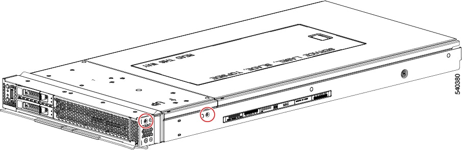
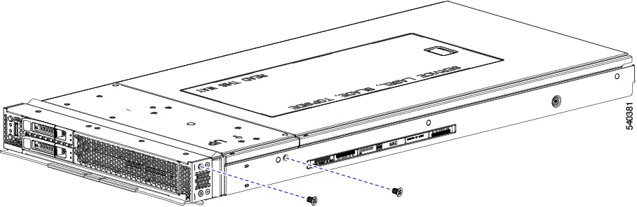
Remove the screws.
|
|
Step 3 |
Grasp the front mezzanine module at the middle of the top front edge and lift the front mezzanine module straight up to remove it from the compute node.
|

What to do next
Connect the front mezzanine GPU module to the compute node. Installing the Front Mezzanine GPU Module
Installing the Front Mezzanine GPU Module
To install the front mezzanine GPU module, you will insert screws on the side of the compute node's sheet metal tray and on the node's motherboard.
Use the following task to install the X10c front mezzanine GPU module.
Before you begin
Review Cabling Considerations for important information before beginning this task.
Procedure
|
Step 1 |
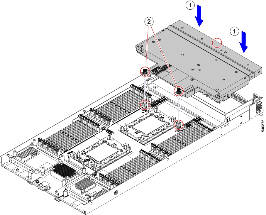
Holding the front mezzanine module by the center of the top edge, keep the module level, and lower it down onto the compute node (1). |
||
|
Step 2 |
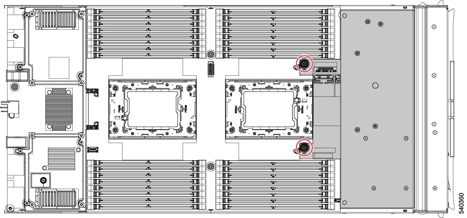
Align the rear captive screws with the threaded standoffs (2).
|
||
|
Step 3 |
Press down evenly on the module to seat the module's connectors into their sockets on the motherboard. |
||
|
Step 4 |
Using a Phillips screwdriver, tighten the two rear captive screws to 5 in-lb of torque. |
||
|
Step 5 |
Using a T8 Torx driver, tighten the four T8 flat head screws on the sides of the compute node (2 screws per side) to secure the module to the compute node.
|
||
|
Step 6 |
Replace the compute node top cover and reinstall the compute node into the chassis. |
 Feedback