Core Components Design Considerations
General Solution Requirements
Data Backup for Your Solution
Run data backup tools only during a scheduled maintenance window. If you use local SQL backups, make sure that the local machine has sufficient capacity. If not, back up to remote storage on the network.
NTP and Time Synchronization
Finesse Time Synchronization:
While time drift occurs naturally, it is critical to configure NTP to keep solution components synchronized. Cisco Finesse server and the Desktop client machines should be time synchronized with the same NTP server (Linux-based NTP v4) for the Duration fields within the Live Data reports to be updated correctly.
Live Data Time Synchronization:
Contact center enterprise solutions require that all parts of the solution have the same time. To prevent time drifts on Live Data reports, the NTP settings on the followinge VMs must be synchronized:
-
Router
-
Logger
-
Administration & Data Server
-
Unified Intelligence Center Publisher and Subscriber
Detailed Contact Center Enterprise Reference Design Topologies
Detailed 2000 Agent Reference Design
This figure shows the logical connections under general operating conditions between the sides in a redundant data center.

Detailed 4000 Agent Reference Design
This figure shows the logical connections under general operating conditions between the sides in a redundant data center.

Detailed 12000 Agent Reference Design
This figure shows the logical connections under general operating conditions between the sides in a redundant data center.

Detailed 24000 Agent Reference Design
For the 24000 Agent Reference Design, the logical connections under general operating conditions follow the pattern of the 12000 Agent Reference Design. However, there are a minimum of 12 CVPs, PGs, and Finesse servers.
Ingress, Egress, and VXML Gateways Design Considerations
IOS Gateway Roles
The contact center enterprise solutions use IOS Gateways for TDM ingress and VXML rendering. You can usually use any Cisco gateway that the solutions support can for either purpose or both. This table lists which call flows use each function:
|
Call Flows |
TDM Ingress |
VXML Rendering |
|---|---|---|
|
Reference Design |
||
|
Comprehensive Using Unified ICM Micro-Apps |
Yes |
Some |
|
Comprehensive Using Unified CVP VXML Server |
Yes |
Some |
|
Non-Reference Design |
||
|
Standalone Self-Service |
Yes |
Yes |
|
Call Director |
Yes |
No |
|
VRU Only with NIC Controlled Routing |
Yes |
Yes |
 Note |
You can use Cisco Virtualized Voice Browser as an alternative for VXML gateways. |
When both Ingress and VXML are required, you can run both functions on the same gateways or designate some gateways for ingress and others for VXML. Use the following guidelines to determine whether to combine or split the functions:
-
In branch office deployments, where the call is queued at the branch where it arrived, always combine the ingress and VXML functions.
-
Where many non-CVP PSTN connections share the gateways, use separate gateways for each function.
-
VXML-only gateways are less costly because they do not require DSP farms or TDM cards.
-
For low call volumes, you generally combine the functions for redundancy purposes. If one combined gateway fails, the other gateway can still process calls at a reduced capacity.
The next decision is whether to use Cisco Integrated Service Router (ISR) or ISR-G2 Gateways.
The classic branch office in which to use ISR Gateways, includes:
-
One of several sites where TDM calls arrive from the PSTN
-
A site that is separated from the main site where most of your solution's equipment resides
-
Each site uses one gateway
TDM-IP Gateway Design Considerations
For the most current information about the various digital (T1/E1) and analog interfaces supported by the various voice gateways, see the latest product documentation available at the following sites:
-
Routers—http://www.cisco.com/cisco/web/psa/default.html?mode=prod&level0=268437899
-
Unified Communications Gateways—http://www.cisco.com/cisco/web/psa/default.html?mode=prod&level0=278875240
Cisco Unified Border Element Design Considerations
The Cisco Unified Border Element (CUBE) is a session border controller (SBC) that provides connectivity between IP voice networks with SIP. Your solution can use physical CUBEs or virtual CUBEs. Your solution can only use CUBE in flow-through mode, where all calls are routed through CUBE.
Note |
Unlike flow-through mode, flow-around mode loses the ability to do DTMF interworking, transcoding, and other key functions, such as telephone and media capabilities. |
Your solution needs a CUBE when replacing a TDM voice circuit with an IP voice trunk from a telephone company. CUBE serves as a feature demarcation point for connecting enterprises to service providers over IP voice trunks.
Note |
For outbound calls, physical CUBE supports Call Progress Analysis (CPA). Virtual CUBE does not support CPA. |
Our testing shows that you can use CUBE in the following scenarios:
-
SIP-to-SIP connectivity between a third-party SIP device and Unified CVP over Cisco-certified SIP trunks.
-
SIP-to-SIP connectivity between Unified CM and Unified CVP.
-
Coresidency of VoiceXML Gateway and CUBE for any of the above scenarios but with the limitation that the call flow does not work when the configurations listed here occur at the same time on the CUBE:
-
Survivability TCL script and incoming translation rules are configured under the same incoming dial-peer.
-
Header-passing between the call legs is enabled globally.
-
For more information about using the CUBE with contact center enterprise solutions, see Cisco Unified Border Element for Contact Center Solutions at http://cisco.com/en/US/docs/voice_ip_comm/unified_communications/cubecc.html.
Note |
For a listing of the maximum sessions that each CUBE supports, see the Cisco Unified Border Element Configuration Guide at http://www.cisco.com/c/en/us/support/routers/cloud-services-router-1000v-series/products-installation-and-configuration-guides-list.html. |
Note |
Due to a limitation in Cisco IOS, the CUBE does not support midcall escalation or descalation from audio to video or the reverse. |
Note |
Currently, CVP does not check the Allowed-Methods in the SIP message. As a result, it passes the Workaround: Disable the |
CUBE Deployment Restrictions
Note the following restrictions when deploying CUBE with SIP Trunks:
-
Configure CUBE in media pass-through mode, the default mode on the dial-peer, in the Unified CVP deployment. Media flow-around mode is supported only in Webex Experience Management.
-
CUBE does not support passing the Refer-To header URI designation from CVP when a REFER call flow is initiated. CUBE rewrites the destination address based on the dial peer configuration. Therefore, configure the dial plan on CVP and CUBE.
-
You cannot use REFER passthrough with Survivability. The script does not let REFER messages be relayed to a SIP service provider regardless of other CUBE configuration.
-
You cannot use REFER consume with Survivability and Router Requery. Survivability always accepts the REFER, even if the transfer does not complete. Unified CCE deems the transfer successful and does not attempt to requery.
-
You cannot use survivability with service provider Alternate Destination Routing (ADR). Manipulation in the script does not let error messages (ring-no-answer or busy) reach the service provider. Use manipulation in the Remote-Party-ID header instead.
-
If GTD is present on the incoming call or if Unified CCE sets a value for the UUI variable, Unified CVP sends a BYE immediately after outpulsing digits in a DTMF transfer. If you need a delay between the digits, use a comma at the end of the label.
-
If GTD is not present on the incoming call, Unified CCE does not set a value for the UUI variable. Then, the service provider does not disconnect a call after receiving digits in a DTMF transfer. Unified CVP sends a BYE request after the SIP.ExternalTransferWait timer expires.
-
Solutions with Courtesy Callback require survivability.
Note |
Call Survivability is supported on CUBE HA mode with the following restrictions:
|
Cisco ASR 1000 Series as a Unified Border Element
Unified CVP supports Cisco IOS XE software with the following limitations:
-
The ASR 1000 Series gateways do not support VXML. So, route the VRU leg of the call to a separate VXML Gateway. Do not use the
Send To Originatorsetting on the CVP Call Server to route the VRU leg of the callback to the originating ASR CUBE Gateway. Route standalone CVP calls to a separate VXML Gateway. -
Unified CVP does not support the global
Pass Thru SDPsetting on the ASR 1000 Series gateways. -
The Courtesy Callback call flow does not work if you configure the ASR as CUBE for the media flow-around, instead of the media flow-through.
-
Typically, you position a proxy server behind the session border controller. If the proxy is in front of the ASR session border controller, use the proxy servers to perform UDP to TCP Up-Conversion when receiving large packet SIP messages. In this case, turn off the proxy servers to ensure that UDP transport is used for the connection on the inbound call.
-
Do not use the following Survivability.tcl options on the ASR. These options are traditionally for POTS dial peers:
-
ani-dnis-split.
-
takeback-method.
-
-- *8.
-
-- hf.
-
icm-tbct.
-
digital-fxo.
-
-
The following Survivability.tcl options are not supported:
-
aa-name—This option is not supported because ASR does not support the CME auto-attendant service.
-
standalone—This option is not supported because ASR does not support VXML.
-
standalone-isntime—This option is not supported because ASR does not support VXML.
-
-
Due to ASR limitations, the following features are not supported:
-
Refer with Re-query
-
Legacy Transfer Connect using DTMF *8 label
-
-
ASR 1000 does not terminate the TDM trunks. Therefore, the following TDM Gateway features do not apply to ASR 1000:
-
PSTN Gateway trunk and DS0 information for SIP calls to Unified CCE
-
Resource Availability Indication (RAI) of DS0 trunk resources through the SIP OPTIONS message to Unified CCE
-
Note |
If your solution uses ASR 1000 Series gateways, it requries an Assessment to Quality (A2Q) review. This review is required for new contact center enterprise solutions and existing solutions that are upgrading to the ASR 1000. |
Cisco ISR as a Unified Border Element
Unified CVP supports ISR with the following limitations:
-
The Courtesy Callback call flow does not work with ISR as CUBE configured for the media flow-around. Configure it for the media flow-through instead.
VXML Gateway Design Considerations
Note |
You can use Cisco Virtualized Voice Browser as an alternative for VXML gateways. |
VXML Gateway with DTMF or ASR/TTS
The VXML Gateway allows customers to interact with the VXML browser through DTMF tones or ASR/TTS. Because the gateway does not have PSTN interfaces, voice traffic is sent using Real-Time Transport Protocol (RTP) to the VXML Gateway. The RFC 2833 uses in-band signaling in RTP packets to transmit DTMF tones. A VXML with DTMF or ASR and TTS allows you to increase the scale of the deployment and support hundreds of VXML sessions.
In a branch office topology, you can deploy a separate PSTN Gateway and a VXML Gateway to provide an extra layer of redundancy In addition, provide support for Survivable Remote Site Telephony (SRST) at the branch office.
VXML Over HTTP
The VXML Server and Voice browser communicate with request-response cycles using VXML over HTTP. Uniform Resource Identifiers (URI) link the VXML documents together. Users input information by web forms similar to HTML. The forms contain input fields that the user edited and sent back to a server.
Resources for the Voice browser are located on the VXML Server. These resources are VXML files, digital audio, instructions for speech recognition (Grammars), and scripts. The VXML browser begins every communication process with the Voice application as a request to the VXML Server. The VXML files contain grammars that specify expected words and phrases. A link contains the URL for the Voice application. The browser connects to that URL when it recovers a match between spoken input and one of the grammars.
Note |
The CVP installer installs the CVP Call Server, the CVP VXML Server, and the Media Server together. |
The following points are key to determining the VXML Server performance:
-
QoS and network bandwidth between the Web application server and the voice gateway
-
Performance on the VXML Server
-
Use of prerecorded audio versus Text-to-Speech (TTS)
Voice user-interface applications tend to use prerecorded audio files wherever possible. Recorded audio sounds better than TTS. Choose the quality of the prerecorded audio fileso that it does not impact download time and browser interpretation. Make the recordings in the 8-bit mu-law 8 kHz format.
-
Audio file caching
Ensure that the voice gateway is set to cache audio content. Caching prevents delays in downloading files from the media source.
-
Use of Grammars
You can discover problems in a voice application only through formal usability testing or observation of the application in use. Poor speech recognition accuracy is a common problem with voice applications. It is most often caused by poor grammar implementation. When users mispronounce words or say things that the grammar designer did not expect, the recognizer cannot match their input against the grammar. Another common problem for grammars is many difficult-to-distinguish entries. These entries result in many incorrectly recognized inputs and decrease the performance of the VXML Server. Improve the recognition accuracy by analysizing its performance and tuning the grammar appropriately.
Distributed Gateways
These sections discuss the types of voice gateways and their effects in a distributed deployment.
Ingress or Egress Voice Gateways at the Branch
Your solution can use Ingress Voice Gateways at a branch office to provide callers with access by local phone numbers, instead of by centralized or nongeographic numbers. This capability is important for solutions that span multiple countries.
Your solution can use Egress Gateways at branches either for a localized PSTN breakout or to integrated decentralized TDM platforms into your solution.
The other components of your solution are centrally located. The WAN links provide data connectivity from each branch location to the main site.
Ingress or VXML Gateway at the Branch
Other voice services that run at the branch can affect the Ingress or VXML Gateways. For example, if the branch is a remote
Unified CM site, Unified CM can support both ACD agent lines and nonagent lines. This deployment uses the PSTN gateway for
new contacts and traffic from the nonagent lines. When a branch has the VXML and Voice Gateway functions on separate devices,
ensure that the dial plan sends the VRU leg to the local VXML resource. This is because the Unified CVP Call Server settransferlabel label applies only to coresident VXML and Voice Gateway configurations.
Colocated VXML Servers and VXML Gateways
Your solution can either have all gateways and servers centralized or have a set of colocated Unified CVP VXML Servers and VXML Gateways at each site.
Colocation has the following advantages:
-
A WAN outage does not affect self-service applications.
-
VXML uses no WAN bandwidth.
Colocation has the following disadvantages:
-
Replicated branch offices require extra Unified CVP VXML Servers.
-
Deploying applications to multiple Unified CVP VXML Servers creates more overhead.
Gateways at Branch with Centralized VXML Server
Advantages of centralized VXML:
-
Administration and reporting are centralized.
-
Branch offices can share Unified CVP VXML Server capacity.
Disadvantages of centralized VXML:
-
Branch survivability is limited.
-
Requires more WAN bandwidth for VXML over HTTP traffic.
Local Trunks in Contact Center Enterprise Solutions
Contact center enterprise solutions have two options for local trunks at the customer premise:
-
Cisco Unified Border Element—Enterprise at the customer premise
-
TDM gateway at the customer premise
Note |
Transcoding resources are not deterministically picked from the local customer premise gateway. |
CVP Design Considerations
CVP Call Server Design Considerations
Unified CVP Algorithm for Routing
When you set up a dial plan and call routing, you can combine Unified CVP features to achieve the required effect. For example, you can use Location Based CAC, SigDigits, SendToOriginator, LocalSRV, and Use Outbound Proxy.
CVP uses this process to formulate the destination SIP URI for the outbound calls from Unified CVP. This description covers CONNECT messages that include labels from the Unified CCE (for example, VXML Gateway, and Unified CM). It also applies for calls to the ringtone service, recording servers, and error message playback service.
Note |
This process only describes calls using the SIP subsystem, which includes audio only and basic video SIP calls. CVP supports the |
The process for creating the destination SIP URI host portion for outbound calls, which includes the Unified CCE label, is as follows:
-
The process starts with the Unified CCE label. The Unified CCE subsystem might already have inserted the Location siteID. If you're using SigDigits, they are prepended. For network VRU labels, the Unified CCE subsystem passes in the entire prefix and correlation ID as the label.
-
If
SendtoOriginatoris matched for the Unified CCE label, the Unified CVP algorithm uses the IP or hostname of the caller (Ingress Voice Gateway). The gateway returns the SIP URI.The setting for
SendtoOriginatoronly applies to callers on Cisco Ingress Voice Gateways (the SIP UserAgent header is selected). Non-Cisco IOS Gateways do not have the CVP bootstrap service that the Cisco IOS VXML Gateway uses. -
If
use outbound proxyis set, then use the host of the proxy and return SIP URI. -
If
local static routeis found for the label, return the SIP URI.Note
Iflocal static routeis not found, the algorithm throws aRouteNotFoundExceptionexception.
Consider these points for calls using the SIP subsystem:
-
To avoid complex Dialed Number strings, do not use the SigDigits feature with Locations CAC siteIDs.
-
You can specify an Outbound Proxy FQDN as a Server Group FQDN (local SRV FQDN). You can also configure a local static route destination as a Server Group FQDN.
-
Ringtone DN (91919191), Recording Server (93939393), and Error message services (92929292) follow the same process.
-
SendtoOriginatorcan work with a REFER label. -
A REFER label can work with the SigDigits setting.
CVP VXML Server Design Considerations
The complexity of your VXML applications affect the performance of the VXML Server. Load test your application for memory leaks and application deadlocks to maintain acceptable VXML Server performance.
CVP Media Server Design Considerations
Voice Prompt Deployment and Management
You can deploy voice prompts with the following methods:
-
Local File System
Store the voice prompt files on a local system. Audio prompt retrieval uses no bandwidth. With this method, Voice Browsers do not have to retrieve audio files for playing prompts, so WAN bandwidth is not affected. However, to change a prompt, you change it on every Voice Browser.
-
IOS VXML Gateway—Prompts are deployed on flash memory.
An IOS VXML Gateway is either a VXML Gateway or a PSTN Gateway, which has the Ingress Voice Gateway and VXML Gateway colocated. Store only critical prompts here, such as error messages or messages for when the WAN is down.
When recorded in G.711 mu-law format, typical prompts are about 10 to 15 KB in size. For these gateways, size the flash memory by factoring in the number of prompts and their sizes. Also leave space for storing the Cisco IOS image.
-
Cisco VVB—Prompts are uploaded on the local file system.
Cisco VVB includes built-in CVP prompts. You can change the
Errortone default prompt through the Cisco VVB Administrator console.
-
-
Media Server
Each local Voice Browser, if configured properly, can cache many prompts, depending on the size of the prompts. Cisco VVB can cache up to 512 MB and Cisco IOS can cache up to 100 MB. To test whether your Media Server is appropriately serving the media files, specify the URL of a prompt on the Media Server in a browser. Your web browser downloads and plays the .wav file without any authentication.
The design of a Media Server deployment depends on the following factors:
-
The number of media files that each gateway plays
-
The network connectivity between the gateway and the Media Server
-
How often you change the media files
Design Considerations for Large Numbers of Media Files
If your gateway plays many different media files to your customers, the gateway might not have space to cache all the media files.
For example, consider an enterprise with many agents. Each agent has their own agent greeting file. You cannot cache all those files in the gateway flash memory.
Colocated Media Server with Voice Browser
One approach to this problem is to colocate the Media Server with the Voice Browser. When a Media Server and Voice Browser coexist on a LAN with plenty of bandwidth, the download of prompts does not add noticeable delay.
Media Server and Voice Browser Distributed Over a WAN
Your solution can have a Media Server separated from a Voice Browser across a WAN.
This figure shows a distributed deployment over WAN.

The download of the media files across a high latency WAN to the Voice Browser can add noticeable delays. The delay can greatly affect the user experience. The delay is proportional to the size and number of media files that are transported across the WAN. You can optimize the delay with Cisco Wide Area Application Services (WAAS).
Design Considerations for Media Streaming
Consider the following factors for both the LAN deployment and the WAN accelerator deployment:
-
Maximum network round-trip time (RTT) delays of 200 ms.
An example is the transfer of files from the CVP Operations Console to the Ingress or the VXML Gateway using Bulk Administration File Transfer (BAFT).
-
Maximum number of streaming sessions supported on each gateway with no additional overhead of video with media forking.
The following table lists the preferred media streaming method for various deployments:
|
Scenario |
Frequency of Change |
Over LAN |
Over WAN |
|---|---|---|---|
|
Small number of files |
Rare |
Cached |
Cached |
|
Small number of files |
Often |
Streamed or Cached |
Streaming with WAAS |
|
Large number of files |
Rare |
Streamed |
Streaming with WAAS |
|
Large number of files |
Often |
Streamed |
Streaming with WAAS |
Design Considerations in using VVB Media Streaming
Streaming service provides continuous audio streaming to callers.
Earlier, continuous audio streaming was supported in IOS Voice XML gateway. In Cisco VVB, the support for audio streaming started in release 12.5 via HTTP(S).
Cisco VVB creates a single connection with a streaming server and broadcasts the audio to all callers while they wait for the call to be answered by an agent. The audio streamed can be a live music or promotional audio. Caching is disabled for the audio streaming.
Cisco VVB requires an internet connection to establish a connection with the streaming server. By default, the audio is streamed for a maximum of 30 minutes per caller. Since there's only one connection with the streaming server, whenever callers connect, they hear the same audio as the rest of the callers (not from the beginning of the audio streaming).
The maximum number of connected callers for a single connection streaming is 50. The application developer can use the streaming service to play a streaming URL from a local or cloud streaming server.
Note |
|
For more information on the streaming property, see the Custom VoiceXML Properties section in the Element Specifications for Cisco Unified CVP VXML Server and Call Studio.
Design Considerations for Media File Deployment
No Support for TCP Socket Persistence
Unified CVP does not support TCP socket persistence.
WAN Acceleration Support
The Cisco Wide Area Application Services (WAAS) system is a set of devices called Wide Area Application Engines (WAEs). The WAEs work together to optimize TCP traffic over your network. Cisco WAAS uses TCP optimization techniques and application acceleration features to overcome the most common challenges in transporting traffic over a WAN. When deployed at the periphery of the network on the VXML Gateway side, Cisco WAAS performs these functions:
-
Changes the TCP header to optimize the traffic.
-
Acts as a large HTTP cache located locally.
-
Uses compression algorithms to further reduce the traffic.
-
Reduces traffic with Data Redundancy Elimination (DRE) techniques.
Cisco WAAS is deployed in inline mode where whole data is forced to pass through the Cisco WAAS.
Media File Deployment on IOS Gateway
Nonstreaming and Streaming Modes
In nonstreaming mode, the VXML gateway downloads the entire audio file from the HTTP server before the Media Player can start playing the prompt. This can cause a delay for the caller. For small files, the delay is only a few milliseconds. You can avoid the delay for larger files by using either caching or streaming mode.
In streaming mode, the Media Player streams the audio in media chunks from the HTTP server to the caller. The Media Player can start playing a prompt when it recieves the first chunk. In streaming mode, the size of the audio prompt does not add any delay for the caller. However, the back-and-forth interactions to fetch the media file in chunks can degrade performance.
Caching the audio files in memory reduces the advantage of streaming large files directly from the HTTP server.
Media File Cache Types
There are two types of cache for storing media files:
- HTTP Client cache
- In nonstreaming mode, the HTTP Client cache stores the entire media file. In streaming mode, the HTTP Client cache stores the first chunk of the media file. The HTTP Client cache stores 100 MB of prompts, in either mode. Any file that is larger than the configured HTTP Client memory file size is not cached.
- VRU Media Player cache
- Nonstreaming mode never uses the VRU Media Player cache. In streaming role, the VRU Media Player cache stores all chunks of the file. In nonstreaming mode, the VRU Media Player cache stores 16 MB. In streaming mode, it can store 32 MB.
Query URL Caching
A query is a URL that has a question mark (?) followed by one or more name=value attribute pairs in it. The Unified CVP VXML Server uses query URLs when generating its dynamic VXML pages. Because each call is unique, data retrieved from a query URL can waste the cache memory. The data is also a possible security risk, because the query URL can contain information such as account numbers or PINs.
Cisco IOS disables Query URL caching by default. To ensure that it is disabled, enter a show run command in Cisco IOS and ensure that the following Cisco IOS command does not appear:
Gateway configuration: http client cache queryMedia File Deployment on Cisco VVB
Cisco VVB includes an HTTP client. The client fetches VXML documents, audio files, and other file resources and stores them in flash memory.
A caching property is associated with VXML resources, audio prompts, grammar files, and script files.
By default, Query URLs are not cached. A query is a URL that has a question mark (?) followed by one or more name=value attribute pairs in it.
Cache Aging
The HTTP Client manages its cache by the freshness of each cached entry. Whether a cached
entry is fresh or stale depends on its Age and
FreshTime. Age is the elapsed time since the file
was last downloaded from the server. FreshTime is the expected time for
the file to stay in the HTTP Client cache since the file was last downloaded.
Several variables affect the FreshTime of a file, such as HTTP message
headers from the server and the cache refresh value.
The FreshTime of a file is determined in the following sequence:
-
When downloaded, if the file has an HTTP message header with the
Cache
                                                Control: max-age
header, theFreshTimeis themax-age. -
If Step 1 does not apply, the
FreshTimeis theExpiresheader minus theDateheader.Note
The HTTP/1.1 specification, RFC 2616 (HyperText Transport Protocol), recommends the use of either the
Cache
                                                            Control: max-age
header or theExpiresheader.
-
If the previous headers are not present, the
FreshTimeis 10% of theDateheader minus theLast-Modifiedheader.
For the Cisco IOS VXML Gateway, you can assign a FreshTime value to the
files with the http client cache refresh command. But, that value only
applies if the previous sequence fails to set a value.
Stale files are refreshed only when needed. A stale cached entry stays in the cache until it is removed to make room for a new file, based on these conditions:
-
The cached entry becomes stale.
-
Its refresh count is zero (0); that is, the cached entry is not being used.
-
The cache needs the memory space to make room for other entries.
When the Age exceeds the FreshTime and the file needs to be played, the HTTP Client checks with the media server to determine whether or not the file has been updated. When the HTTP Client sends a GET request to the server, it uses a conditional GET to minimize its impact on network traffic. The GET request includes an If-Modified-Since in the headers sent to the server. With this header, the server returns a 304 response code (Not Modified) or returns the entire file if the file was updated recently. When the Age exceeds the FreshTime and the file needs to be played, the HTTP Client checks with the media server to determine whether or not the file has been updated. When the HTTP Client sends a GET request to the server, it uses a conditional GET to minimize its impact on network traffic. The GET request includes an If-Modified-Since in the headers sent to the server. With this header, the server returns a 304 response code (Not Modified) or returns the entire file if the file was updated recently.
This conditional GET applies only to nonstreaming mode. In streaming mode, the HTTP Client always issues an unconditional GET. There is no If-Modified-Since header included in the GET request that results in an unconditional reload for each GET in streaming mode.
CVP Reporting Server Design Considerations
The CVP Reporting Server houses the Reporting Service and hosts an IBM Informix Dynamic Server (IDS) database management system. The database's schema is available to enable you to write custom reports for the database. The Reporting Service does not itself perform the database administrative and maintenance activities, such as backups or purges. However, Unified CVP provides access to such maintenance tasks through the Operations Console.
The Reporting Service:
-
Provides historical reporting of self-service activity in your contact center. The service summarizes call activity for the contact center managers.
-
Can also provide operational analysis of various VRU applications.
-
Receives reporting data from the IVR Service of VXML server and the SIP Service. The Reporting Service transforms and writes this data into the Informix database.
Your solution can use either a single of multiple CVP Reporting Servers. A single Reporting Server does not necessarily represent a single point of failure. The database management system provides data safety and security. Your solution can tolerate temporary outages due to persistent buffering of information on the source components.
If your solution uses multiple Reporting Servers, you can associate each CVP Call Server with only one Reporting Server. Also, your reports cannot span multiple Informix databases.
Note |
Unified CVP subcomponents cannot synchronize the machine time themselves. Provide a cross-component time synchronization feature, such as NTP, to assure accurate time stamps for logging and reporting. |
CVP Reporting Server Features
Consider the following points when designing your solution with the CVP Reporting Server:
-
You can size the Informix database up to 100 GB. You cannot use a 2 GB or smaller database in a production environment.
-
The Reporting Server supports the Analysis Manager tool. The Analysis Manager can query the Reporting Server with an authenticated user's credentials.
-
The Reporting Server aggregates Unified CVP data in 15-minute increments. Cisco Unified Intelligence Center provides templates to display call data and dominant path information at 15-minute, daily, and weekly intervals.
-
All metadata for administrative processes is in the
Ciscoadmindatabase. This location removes the tables from the general view of reporting users. -
All database backup files are compressed and stored on the Reporting Server. The backup file is called cvp_backup_data.gz and is stored on the %INFORMIXBACKUP% drive in the cvp_db_backup folder.
-
Using the system CLI, you can make the request to list log files on the Reporting Server (show log). This request includes the Informix Database Server Engine logs. The show tech-support command also includes these files.
-
With the debug level 3 (or 0) command from within the System CLI, you can turn on and turn off the debug. When turned on, this command generates trace files for all administrative procedures, Purge, Statistics, and Aggregator.
Note
After the command is turned on, trace files place an elevated burden on the database.
-
Log data for administrative procedures are written on a nightly basis to the %CVP_HOME%\logs folder.
-
All the StartDateTime, EndDateTime, and EventDateTime values are stored as UTC in Reporting Server tables.
-
Transfer Type data and Transfer Labels for SIP call events are stored in the call event table.
-
Summary purge results are logged in the log table.
-
Three new scheduled tasks have been added to the Reporting Server scheduler:
-
CVPSummary, which builds summary tables.
-
CVPCallArchive, which archives Callback data to maintain callback database performance.
-
CVPLogDump, which extracts the administrative logs on a nightly basis.
-
CVP Backup and Restore
Using the Operations Console, you can schedule daily database backups or run database backups on-demand. In a major failure, you can restore the database manually to the last backup time. This limits the loss of data to 24 hours at most.
CVP Call Studio Design Considerations
When you design applications in CVP Call Studio, keep the applications small and closely mapped to your business flows. Large applications are harder to maintain and work with. Maintain a balance between subflows and independent applications.
Unified CVP Coresidency
To calculate the number of servers required with SIP call control, use this formula:
(Self Service + Queue and Collect + Talking) / 3000, rounded up Where:
Self Service is the number of calls that require SIP call control and run an application on the VXML Server.
Queue and Collect is the number of calls that require SIP call control and run an application using Microapps only on the Call Server.
Talking is the number of calls at agents.
The following example applies for VXML and HTTP sessions only.
((3000) + (500) + 3700) / 3000 = 3 servers If you use CUBE as a Session Border Controller (SBC) for flow-through calls to handle VXML requirements, use the sizing information provided in the example.
If you use CUBE as a Session Border Controller (SBC) to handle flow-through calls only (no VXML), then consider Voice Activity Detection (VAD) and see the sizing information in the Cisco Unified Border Element Ordering Guide, available at http://www.cisco.com/c/en/us/products/collateral/unified-communications/unified-border-element/order_guide_c07_462222.html.
Contact Center Enterprise Design Considerations
The contact center enterprise software provides enterprise-wide distribution of multichannel contacts. It can support inbound and outbound phone calls, web collaboration requests, email messages, and chat requests. It can also support geographically separated contact centers. The contact center enterprise software is an open standards-based solution that includes routing, queuing, monitoring, and fault tolerance capabilities.
Note |
Unified CCE is the name for both one of the contact center enterprise solutions and one of the core components for all of the solutions. |
Router Design Considerations
You can geographically distribute redundant Unified CCE servers or locate them at the same physical site. In a production deployment, the Router and Logger must connect over a private network that is isolated from the public network.

Note |
You can use the same private network path for the Central Controller and PGs. |
Logger Design Considerations
The design of the Logger database holds two weeks of data usually. This period allows enough time for the data to replicate to the AW-HDS-DDS.
The Logger uses the same private network path as its Router.
Peripheral Gateway Design Considerations
Agent Peripheral Gateway Design Considerations
The Agent PG communicates with the Unified CM cluster through the CTI Manager. An Agent PG can control agent phones and CTI route points anywhere in the cluster. The Agent PG registers with the CTI Manager on a Unified CM subscriber in the cluster. The CTI Manager accepts all JTAPI requests from the PG for the cluster. When the PG requests a phone or route point on another subscriber, the CTI Manager forwards the request to the other subscriber.
Note |
The Agent PG is the PG that includes the Unified CM PIM. It is sometimes called a Unified CM PG. In Non-Reference Designs only, the Agent PG might be a Generic PG. |
A fault-tolerant design deploys Agent PGs in a redundant configuration, because a PG only connects to the cluster through a single CTI Manager. If that CTI Manager fails, the PG cannot communicate with the cluster. A redundant PG provides a secondary pathway through a different CTI Manager on a different subscriber in the cluster.
The minimum design for a high-availability cluster is one publisher and two subscribers. If the primary subscriber fails, the devices rehome to the secondary subscriber and not to the publisher for the cluster.

The redundant PGs keep in synchronization through a private network that is isolated from the public network. If the two PG servers are geographically distributed, use a separate WAN connection for the private network. To avoid a single point of failure in the network, do not use the same circuits or network gear as for the public network.
Within the Agent PG, the JTAPI Gateway and Unified CM PIM manage the connectivity to the cluster. The JTAPI Gateway handles the JTAPI socket connection protocol and messaging between the PIM and the CTI Manager. The PIM manages the interface between Unified CCE, the JTAPI Gateway, and the cluster. It requests specific objects to monitor and handle route requests from the cluster. The PG starts the JTAPI Gateway and PIM automatically as node-managed processes. The PG monitors the processes and automatically restarts them if they fail.
The JTAPI services from both redundant Agent PGs sign in to the CTI Manager after initialization. Agent PG-A signs in to the primary CTI Manager; Agent PG-B signs in to the secondary CTI Manager. Only one PG in each pair actively registers and monitors phones and CTI route points. The redundant PG runs in hot-standby mode. The redundant PG signs into the secondary CTI Manager only to initialize the interface and make it available for a failover. This arrangement significantly decreases the time for the failover.
When the system starts, the PG that first connects to the Router server and requests configuration information is the active PG. The Router ensures that the PG with the best connection becomes active. The nominal designations of “Side A” and “Side B” do not affect which PG becomes active. During a PG failover caused by a private link failure, a weighting mechanism chooses which PG is active to minimize the impact on the contact center.
If calls arrive at the CTI Route Points before the PIM is operational, the calls fail
unless you set up a recovery number. Place the recovery number in the route points'
Call Forward on Unregistered or Call Forward on
Failure setting. For example, you can set the recovery numbers to the Cisco
Unity voicemail system for the Auto Attendant.
Note |
You cannot use the DN for a CTI Route Point on a different CTI Route Point in another partition. Ensure that DNs are unique across all CTI Route Points on all partitions. |
Active PG Shutdowns
Avoid shutting down an active peripheral gateway service in your production environment. This causes a service interruption of a minute or more while the other side connects and activates. The length of the interruption depends on the size of the configuration and the type of peripheral. For example, the VRU peripheral usually takes less time. The other side for the VRU might take 30 seconds or less to reactivate.
Voice Response Unit Peripheral Gateway Design Considerations
In the standard three PG model, the VRU PG includes two PIMs with a 1:1 pairing to a CVP servers on Side A and Side B.
Media Resource Peripheral Gateway Design Considerations
In the standard three PG model, the MR PG includes PIMs to support these functions:
-
Outbound Option
-
Enterprise Chat and Email
-
Customer Collaboration Platform—This PIM handles Task Routing and Agent Request.
-
Third-party integrations
Administration & Data Server Design Considerations
Administration & Data Server Limits by Reference Design
You can deploy only so many Administration & Data Servers for each Logger.
| Component on each Logger side | 2000 Agent | 4000 Agent | 12,000 Agent |
|---|---|---|---|
|
AW-HDS-DDS |
1 per side, installed on the same server with the core components. |
2 per side |
NA |
|
HDS-DDS |
NA |
NA |
1 per side |
|
AW-HDS |
Optionally, either 1 AW-HDS or AW-HDS-DDS per side, installed on a separate server from the core components |
NA |
3 per side |
|
Real-Time Distributors only1 |
2 per side |
2 per side |
5 per side |
Note |
Each Real-Time Distributor can support 64 users. |
Live Data Server Design Considerations
Reporting Clients by Live Data Configuration
Use the Live Data coresident configuration for 2000 Agent Reference Designs. For solutions with a standalone Live Data server, you typically use the small Live Data deployment configuration with a Unified CCE Rogger deployment. You typically use the large Live Data deployment configuration with a separate Router and Logger.
Note |
The standard Cisco Finesse agent desktop includes the Live Data gadget. |
Cisco Virtualized Voice Browser Design Considerations
The number of Virtualized Voice Browsers that your solution requires depends on the VRU ports that your solution needs on the VXML Gateway. Install Cisco VVB depending on the number of SIP sessions required for your solution. This table lists feature support by Cisco VVB:
|
Platform or Feature |
Cisco Virtualized Voice Browser Considerations |
|---|---|
|
Voice Codec |
G711 |
|
Call Flows |
Standalone and Comprehensive with call survivability are supported. |
|
ASR/TTS |
Supported |
|
Courtesy Callback |
Supported |
|
HTTP |
Supported |
|
HTTPS |
Supported |
|
Local Prompts |
Supported |
|
Local Hostname Resolution |
Supported |
|
MRCP v1 and v2 |
Supported |
|
VXML 2.0 and 2.1 |
Supported |
|
RTSP Streaming |
Not Supported |
|
Video |
Not Supported |
Unified Communications Manager Design Considerations
Note |
The Reference Design layouts use a 7500 user Unified CM OVA which supports 2000 contact center enterprise agents on each redundant pair of subscribers. If you use a different Unified CM OVA, move the cluster off the servers in the Reference Design layout or comply with the specification-based hardware policy. See the Cisco Collaboration Virtualization page for your solution at http://www.cisco.com/c/dam/en/us/td/docs/voice_ip_comm/uc_system/virtualization/cisco-collaboration-virtualization.html for details on the specification-based policy. |
Cisco Unified Communications Manager (Unified CM) connects calls passed from Unified CVP to the agent that Unified CCE chose. Unified CVP transfers callers to Unified CCE agent phones or desktops using SIP. The Unified CVP Call Server receives an agent label from Unified CCE and routes the call using SIP proxy. The call is then sent to the appropriate Unified CM subscriber in the cluster, which connects the caller to the agent. The Call Server proxies the call signaling, so it remains in the call signaling path after the transfer is completed. However, the RTP stream flows directly from the originating gateway to the phone.
All contact center enterprise solutions use redundant Unified CM, Unified CCE, and Unified CVP components. Because of the redundancy, your solution can lose half of its core systems and be still operational. In that state, a solution handles calls by rerouting them through Unified CVP to a VRU session or an agent on the still-operational components. Where possible, deploy Unified CCE so that no devices, call processing, or CTI Manager services run on the Unified CM publisher.
To enable automatic failover and recovery, pairs of redundant components interconnect over private network paths. The components use TCP heartbeat messages for failure detection. Unified CM uses a cluster design for failover and recovery. Each cluster contains a Unified CM publisher and multiple UM subscribers. Agent phones and computers register with a primary target but automatically reregister with a backup target if the primary fails.
To set up a Unified CM cluster for your contact center enterprise solution:
-
Configure a SIP trunk in Unified CM.
-
When configuring agent labels, consider which device is the routing client. When the label is returned directly to Unified CM, Unified CM is the routing client. When the label is sent to Unified CVP, associate the labels with each of the Unified CVP Switch leg Call Servers.
Unified CM Connection to the Agent PG
You can deploy Agent PGs to connect to a Unified Communications Manager cluster in the following ways:
-
Deploy an Agent PG for each pair of subscribers. Each subscriber runs the CTI Manager service. Each Agent PG connects to a CTI Manager running on its corresponding subscriber pair. This figure shows an example where four primary subscribers are required and four backup subscribers are deployed to provide 1:1 redundancy.
Figure 7. Deploy Agent PG for Each Pair of Subscribers in a Cluster 
This figure shows the connections between the components in a solution with two Agent PG pairs and a cluster with four subscribers.
Figure 8. 2 Agent PG Pairs for Unified CM Cluster 
-
Deploy a single Agent PG for the entire cluster. This type of deployment requires a single pair of subscribers running CTI Manager. Spread agent phone registration among all the subscribers, including the subscribers running the CTI Manager service. The following diagram shows an example where four primary subscribers are required and four backup subscribers are deployed to provide 1:1 redundancy.
Figure 9. Deploy Single Agent PG for Entire Cluster 
Note
Use this option when your cluster supports both back-office phones and agent phones.
This figure shows the connections between the components in a solution with two Agent PG pairs and a cluster with four subscribers.
Figure 10. Single Agent PG Pair for Entire Unified CM Cluster This model reduces the server count for the PG. Another benefit is that there is a single PIM for the entire cluster. So, you can create teams that span across many subscribers. This allows supervisors, for example, to monitor agent phones registered to any subscriber in the cluster. However, this deployment can have slightly higher resource usage on the cluster. Use the Cisco Unified Communications Manager Capacity Tool to size the Unified CM servers for your solution.
Single-line and Multi-line Feature Support
Single-line and Multi-line Support
Unified CCE supports Unified CM-based monitoring of a single line and multiple agent lines. Multi-line supports the following capabilities:
-
Monitoring and reporting of calls on all lines.
-
Other than call initiation, all other call controls on the non-ACD extensions are supported from multi-line capable desktops. Calls initiated from the desk phone can be controlled after initial call setup.
-
Requires a maximum of two call appearances.
-
Supports a maximum of four lines per phone, one ACD line and up to three non-ACD lines.
-
Supports shared lines on ACD and non-ACD lines. Please see table below for differences.
-
You can configure multiple devices with a shared non-ACD line, but can only sign in an Agent into one device. Unified CCE supports Shared lines to enable agents with voice facilities at both home and work to share a voicemail line.
Note
A shared non-ACD Line does not support Non ACD Line Impact configuration in PG Explorer.
-
Unified CCE may not be backward compatible with third-party CTI applications when Multi-Line Agent Mode is enabled. Validate Multi-line support with the third-party vendor.
Single-line Versus Multi-line Behavior
|
Action |
Single-line behavior |
Multi-line behavior |
||
|---|---|---|---|---|
|
Accept a routed call while call is on second line? |
Yes |
Yes, when Non ACD Line Impact is set to ensure there is no impact for the deployment. |
||
|
Supervisor Monitor using Unified CM-based silent monitor |
Yes |
Yes.
|
||
|
Call park |
Supported on unmonitored second line |
Not supported because all lines are monitored. |
||
|
Call Waiting / Busy trigger > 1 |
Supported |
No longer supported. Hard-coded to 1 on 69xx series phones (must be configured before enabling multi-line). |
||
|
Reporting on second line calls |
Use CDRs in Unified CM |
Termination Call Detail Records for call to or from an agent's Non ACD line with an unmonitored device or another agent's Non ACD line is reported with a Non ACD Peripheral Call Type. Reporting for all calls on the Non-ACD line is captured in the Agent Interval table for that agent. |
||
|
Number of configured lines on phone |
No limit described (only monitoring one line) |
Do not configure more than four lines. If you do, the agent cannot sign in on any of the lines. This generates a configuration alert. |
||
|
Shared ACD Line |
Shared lines are supported on the ACD line for up to two devices. Device control is selected via the device itself, by going off-hook or making or receiving a call. |
Shared lines are supported on the ACD line for up to two devices. Device control is selected via the device itself, by going off-hook or making or receiving a call. |
||
|
Non-ACD shared line You can configure multiple devices with a shared non-ACD line, but can only sign in an Agent into one device. Unified CCE supports Shared lines to enable agents with voice facilities at both home and work to share a voicemail line.
|
Supported on unmonitored line; no configuration limitations |
Support for non-ACD lines is limited to having one agent login to a device that has a common second line. The agent cannot sign in on both phones at the same time. Another agent cannot sign into another device which has the same common line. |
MTP Usage on the Unified CM Trunk
If your solution uses the Unified CM SIP Trunk, certain call flows, such as Cisco Unity Voice Mail or Mobile Agent, might require an MTP resource.
This is necessary when the negotiated media capabilities of the endpoints do not match, such as with the DTMF in-band versus out-of-band capability. In this case, Unified CM dynamically allocates an MTP due to the DTMF media capabilities mismatch.
Your solution might also require MTPs when interoperating with third–party devices.
Mobile and Remote Access
The Cisco Collaboration Edge architecture includes Unified Communications Mobile and Remote Access (MRA) to enable access by devices that are not in the enterprise network. MRA uses Expressway to provide secure firewall traversal and support for Unified CM registrations. Unified CM can then provide supported devices with call control, provisioning, messaging, and presence services.
For details on Collaboration Edge, see the documentation at http://www.cisco.com/c/en/us/support/unified-communications/unified-communications-system/tsd-products-support-series-home.html. For details on Expressway deployment and configuration, see the documentation at http://www.cisco.com/c/en/us/support/unified-communications/expressway-series/tsd-products-support-series-home.html. See the Compatability Matrix for your solution for details of device support for MRA.
If your solution uses MRA, consider these points:
-
The connection between the Cisco Finesse client and server is over a VPN, not over the MRA connection.
-
Certain phones do not support Extension Mobility over MRA.
-
Contact center enterprise video deployments do not support MRA.
-
If you have VPN split-tunneling configured, you can use Jabber with MRA and the Finesse desktop on the same client machine. See https://www.cisco.com/c/en/us/support/security/anyconnect-secure-mobility-client/products-installation-and-configuration-guides-list.html for Cisco AnyConnect Mobility Client Split-Tunneling configuration.
-
If VPN split-tunneling is not available, you can run after splitting them onto two clients.
-
A remote agent who runs Jabber with MRA on one client machine and the Finesse desktop with a VPN connection on a second client machine.
-
A remote agent who runs a Jabber softphone on a laptop that is connected over MRA and runs the Finesse desktop as a Xenapp thin client.
-
Cisco Finesse Design Considerations
Cisco Finesse is a supervisor and agent desktop for use with contact center enterprise solutions. You install the Cisco Finesse server on a VM. Clients then use a web browser to point to the Cisco Finesse server. No Cisco Finesse software is installed on the client, which speeds and simplifies installation and upgrade.
See the Contact Center Enterprise Compatibility Matrix for supported browsers and operating systems for Cisco Finesse clients (administration console, agent desktop, and supervisor desktop).
The Cisco Finesse desktop application consists of the client and server components. The client uses standard web programming elements (HTML, JavaScript) that are distributed as gadgets using the OpenSocial 1.0 specification. You can configure the agent desktop to use Cisco and third-party gadgets through a layout management mechanism.
Cisco Finesse is part of a class of applications called Enterprise Mashups. An Enterprise Mashup is a web-centric method of combining applications on the client side. The gadget-based architecture of Cisco Finesse enables client-side mashup and easier integration. There are fewer version compatibility dependencies because gadget upgrades are handled independently.
You can customize the agent and supervisor desktops through the Cisco Finesse administration console. Administrators can define the tab names that appear on the desktops and configure which gadgets appear on each tab.
This table summarizes the capabilities of Cisco Finesse:
|
Desktop Functionality |
Cisco Finesse |
||
|---|---|---|---|
|
Desktop Chat |
Yes |
||
|
Team Message |
Yes |
||
|
Browser-based desktops |
Yes |
||
|
Custom development |
Yes (using standard web components such as HTML, JavaScript) |
||
|
Desktop security |
Yes
|
||
|
Workflow automation |
Yes |
||
|
Mobile (remote) agents |
Yes |
||
|
Silent monitoring |
Yes |
||
|
Monitor mode applications |
NA |
||
|
Outbound calls |
Yes |
||
|
Microsoft Terminal Services support |
NA |
||
|
Citrix presentation server support |
NA |
||
|
Agent mobility |
Yes |
||
|
Agent Greeting |
Yes |
Cisco Finesse REST API
Cisco Finesse provides a REST API for client applications to access the supported server features. The REST API transports XML payloads over HTTPS.
Cisco Finesse also provides a JavaScript library and sample gadget code to aid third-party integration. You can find the developer documentation for the REST API, the JavaScript library, and sample gadgets on the Cisco Developer Network at https://developer.cisco.com/site/finesse/.
Cisco Finesse Agent Desktop
Out of the box, the agent desktop provides the following features:
-
Basic call control (answer, hold, retrieve, end, and make a call)
-
Advanced call control (consultation, transfer after consult, conference after consult)
-
Single-step transfer (agents can transfer a call without first initiating a consultation call)
-
Queue statistics gadget (to view information about the queues to which the agent is assigned)
-
View of the agent's Call History and State History
-
Not Ready and Sign Out reason codes
-
Contact lists
-
Workflows
-
Mobile agent support
-
Progressive, Predictive, Preview Outbound, and Direct Preview Outbound
-
Desktop Chat
-
Team Message
Cisco Finesse Supervisor Desktop
The Cisco Finesse supervisor features extend the agent desktop with more supervisor-only gadgets. These features include the following:
-
Team performance gadget to view the agent status
-
Queue statistics gadget to view queue (skill group) statistics for the supervisor's queues
-
View of the supervisor's Call History and State History
-
View the Call History and State History of any agent in the supervisor's team
-
Agent Call Information from Team Performance Gadget (TPG)
-
Unified CM Silent Monitoring
-
Barge-in
-
Intercept
-
Change agent state (A supervisor can sign out an agent, force an agent into Not Ready state, or force an agent into Ready state.)
Cisco Finesse IP Phone Agent
With Cisco Finesse IP Phone Agent (IPPA), agents can access Cisco Finesse capabilities on their Cisco IP Phone instead of through the browser. Cisco Finesse IPPA only provides a subset of Cisco Finesse features that are available on the browser. It enables agents and supervisors to receive and manage Cisco Finesse calls without access to a PC.
Note |
Supervisors can only perform agent tasks on their IP Phones. Cisco Finesse IPPA does not support supervisor tasks, such as monitor, barge, and intercept. |
Cisco Finesse IPPA supports the following functionality:
-
Sign in and out
-
Call variables display
-
Pending state
-
Wrap-up reasons
-
Optional wrap-up
-
Not Ready reasons
-
State change using reason codes
-
One Button Sign In
Cisco Finesse Administration Console
Cisco Finesse includes an administrative application that allows administrators to configure the following:
-
Connections to the CTI server and the Administration & Data Server database
-
Cluster settings for VOS replication
-
Not ready and sign out reason codes
-
Wrap-up reasons
-
Contact lists
-
Workflows and workflow actions
-
Call variable and ECC variable layouts
-
Desktop layout
-
Desktop Chat server settings
-
Team resources
-
Cisco Finesse IP Phone Agent (IPPA)
Reason codes, wrap-up reasons, contact lists, workflows, and desktop layouts can be global (apply to all agents) or assigned to specific teams.
Cisco Finesse Deployment Considerations
Cisco Finesse and the Multiline Feature
Cisco Finesse supports the configuration of multiple lines on agent phones if Unified CCE is configured for multiline. You can configure several secondary lines on an agent phone. However, the Cisco Finesse server blocks any events that the CTI server sends in response to operations on secondary lines. The Cisco Finesse server does not publish these events to the Cisco Finesse clients. Information about calls on secondary lines does not appear on the Cisco Finesse desktop.
If your agents use 8900 Series or 9900 Series phones, enable Multi-Line on the Unified CM peripheral. This configuration option is a peripheral-wide option. If you enable Multi-Line for even one agent with an 8900 Series or 9900 Series phone, enable it for all agents.
To support multiline, configure all phones with the following settings:
-
Set Maximum number of calls to 2.
-
Set Busy trigger to 1.
Cisco Finesse with Citrix
Contact center enterprise solutions support running the Cisco Finesse desktop within a Citrix environment. Cisco Finesse supports Citrix XenApp and XenDesktop.
Note |
AWs, Configuration-Only Administration Servers, and Administration Clients can operate only as a single remote instance on a given VM. |
For more information about supported versions, see the Compatibility Matrix for your solution at https://www.cisco.com/c/en/us/support/customer-collaboration/unified-contact-center-enterprise/products-device-support-tables-list.html.
Cisco Finesse with NAT and Firewalls
Some solutions have two or more disjointed networks that interconnect with Network Address Translation (NAT).
Cisco Finesse provides limited support for NAT. Cisco Finesse supports basic NAT (one-to-one IP address mapping) between the Cisco Finesse servers and clients.
The following caveats apply to Cisco Finesse and NAT:
-
You cannot use PAT/NPAT (one-to-many address mapping that uses ports) between the Cisco Finesse servers and clients.
-
You cannot use NAT between the Cisco Finesse servers and any of the servers to which they connect (such as Unified CCE or Unified CM servers).
-
Cisco Finesse IP Phone Agent (IPPA) does not support NAT.
Note |
For more information about NAT and firewalls, see the chapter on solution security. |
IP Phone and IP Communicator Support
Cisco Finesse supports the use of Cisco IP hardware phones and the Cisco IP Communicator software phone.
For more information about the supported phone models and IP Communicator versions, see the Compatibility Matrix for your solution at https://www.cisco.com/c/en/us/support/customer-collaboration/unified-contact-center-enterprise/products-device-support-tables-list.html.
IP Phones and Silent Monitoring
Silent monitoring supports both IP hardware phones and Cisco IP Communicator.
IP Phones and Mobile Agent
The Mobile Agent feature does not require any specific type of phone. You can even use analog phones with this feature.
IP Phones and Citrix or MTS
Cisco Finesse supports both IP hardware phones and Cisco IP Communicator when using Citrix or MTS.
In these environments, install Cisco IP Communicator on the agent desktop PC. You cannot deploy Cisco IP Communicator on the Citrix or MTS server.
Cisco Finesse and Cisco Jabber
Cisco Finesse supports Cisco Jabber for Windows as a contact center enterprise voice endpoint. Cisco Finesse supports the following Jabber functionality:
-
Voice and Video
-
Built-In Bridge (BIB) for silent monitoring
-
IM and Presence
Note |
Agents cannot use Jabber to transfer or conference calls. Agents must use the Cisco Finesse desktop for transfer and conference. |
To use Jabber with Cisco Finesse, change the default Jabber configuration as follows:
-
Change Maximum number of calls from 6 to 2.
-
Change Busy trigger from 2 to 1.
For more information on support for Jabber, see the Compatibility Matrix for your solution at https://www.cisco.com/c/en/us/support/customer-collaboration/unified-contact-center-enterprise/products-device-support-tables-list.html.
Desktop Chat
Desktop Chat is a XMPP browser based chat, which is powered by Cisco Instant Messaging and Presence (IM&P) service. Desktop Chat allows agents, supervisors, and Subject Matter Experts (SMEs) within the organization to chat with each other.
For more details see, https://www.cisco.com/c/en/us/support/unified-communications/unified-communications-manager-callmanager/products-implementation-design-guides-list.html.
Instant Messaging and Presence (IM&P) provides presence and chat capabilities within the Unified CM platform. The Desktop Chat interface is hosted by the Finesse Agent desktop and requires a separate log in to the IM&P service.
Note |
In HCS deployments, the Desktop Chat user search functionality shows all the users available from LDAP and is not restricted to the users from the corresponding customer whose agent or supervisor initiated the search. In HCS deployments from Release 12.5(1), the desktop chat user search displays all the users from LDAP by default. You can refine this search to display the users from the corresponding customer whose Agent or Supervisor initiated the search, based on the Organization Unit (OU) defined in Cisco Unified Communications Manager IM and Presence Service. This is supported on Cisco Unified Communications Manager IM and Presence Service, Release 12.5(1)SU2 ES build version 12.5.1.12900-26 onwards. Contact Cisco TAC for more details. Desktop Chat does not support Cisco Mobile Remote Agent /VPN based access to the IM&P server. Desktop Chat requires direct access to the IM&P server to connect to the chat service. |
For more information, see Desktop Chat Server Settings section in Cisco Finesse Administration Guide at https://www.cisco.com/c/en/us/support/customer-collaboration/finesse/products-maintenance-guides-list.html.
Cisco Instant Messaging and Presence (IM&P)
IM&P incorporates the Jabber platform and supports XMPP protocol and can track the user's presence via multiple devices. IM&P pulls its user list from users who have been enabled for chat capabilities, from Unified CM (or LDAP if LDAP integration is enabled). Only Unified CM users enabled for chat capability can login to IM&P.
Cisco IM&P supports multiple forms of clustered deployment to provide high availability. Finesse is configured with a specific Agent PG. This Agent PG is connected to a Unified CM that associated with a specific IM&P cluster. Configure Finesse to connect to this IM&P cluster.
Identity, Presence, Jabber
A User is identified in the IM&P service with a unique identity which is in the form of username@FQDN.com.
In Unified CCE, the identity is not the same as the username or peripheralID configured in Unified CCE.
A user is described in terms of the identity of the user, presence status, (available, unavailable, or busy) and the presence capabilities of the user.
The presence status of the user is not related to the Agent Status and has to be managed independently by the user post login.
Cisco IM&P service combines the presence status of user across multiple devices and publishes them for subscribers who have added the contact in their contact list.
IM&P supports a composed presence for the users, which is derived from the state matrix of all the devices that the agent is logged into. Cisco IM&P takes sources of presence from the XMPP client for the user, on-hook and off-hook status from CUCM, and in a meeting status from Microsoft Exchange to generate the users overall composed presence. Desktop Chat displays the composed presence of the user. For details about how to arrive at the composed presence, refer to the Cisco IM&P User Guide at: https://www.cisco.com/c/en/us/support/unified-communications/unified-communications-manager-callmanager/products-user-guide-list.html .
Irrespective of the deployment type, the Desktop Chat requires an explicit login using the IM&P identity of the user after logging into the Finesse Desktop.
SSO is not supported with Desktop Chat and thus an explicit login is required in SSO mode.
Desktop Chat presence indicates the availability of users to communicate across the configured devices.
Desktop Chat availability will also be reflected in the combined IM&P presence of the user.
Logging into Desktop Chat, by default sets the users state as available.
An agent logging into Desktop Chat can thus be seen as available in Jabber or other XMPP platforms connected with IM&P and can communicate with these users.
Note |
File transfer is supported only for users communicating using Desktop Chat. For more information on the supported file types and the maximum size of file attachments see, Desktop Properties CLIs section in the Cisco Unified Contact Center Express Administration and Operations Guide. |
Example for Desktop Chat availability:
A Desktop Chat user can be logged into the Desktop Chat and Jabber at the same time. Incoming chats will be relayed to all the logged in clients including Desktop Chat. However, Desktop Chat does not support Multi-Device-Messaging. So messages being sent from other XMPP clients like Jabber will not be displayed within the Desktop Chat. Once alternate clients are used to respond to incoming chats, further messages are not shown in Desktop Chat until the user starts responding using the Desktop Chat.
For more information on network designs, refer to the Solution Reference Network Design guide https://www.cisco.com/c/en/us/support/unified-communications/unified-communications-manager-callmanager/products-implementation-design-guides-list.html.
Cisco IM&P Design Considerations
Finesse browser makes a separate connection to Cisco IM&P over HTTPS, after it retrieves the chat server URI from the Finesse server. This requires separate certificates to be accepted if self-signed certificates are employed, in an HTTPS deployment.
The chat interaction happens over XMPP protocol, on the HTTP connection with long polling or BOSH established with Cisco IM&P.
There are no other interactions between Finesse server and browser for chat related capabilities, except for retrieving the Cisco IM&P server configurations.
Chat log persistence is available with the browser during the desktop session.
User search capabilities require Unified CM LDAP integration. In its absence, remote contacts have to be manually added by the user.
If the user is an existing Jabber user, the same contacts are shared between the Desktop Chat and Jabber which are also persisted across sessions.
There are no limits on the number of ongoing chats or the contacts in Desktop Chat apart from the restrictions or guidelines advised by Cisco IM&P. For the limit on the number of ongoing chats or the contacts and how to configure the Cisco IM&P server for chat, see the IM&P Solution Reference Networking Guide.
Note |
Desktop Chat requires the Cisco IM and Presence certificates to be trusted. For more information on accepting certificates, see the Accept Security Certificates section, in the Common Tasks chapter of Cisco Finesse Agent and Supervisor Desktop User Guide for Cisco Unified Contact Center Express at https://www.cisco.com/c/en/us/support/customer-collaboration/unified-contact-center-express/products-user-guide-list.html. |
Cisco IM&P Deployment Considerations
Finesse is configured to the primary and secondary IM&P chat servers through the Cisco Finesse Administration interface.
Desktop Chat automatically discovers the appropriate IM&P node, configured for the user, by connecting to the configured servers and connects to the appropriate nodes in IM&P. This resolution is only performed for the first time chat is loaded and subsequently uses the same nodes, until the browser cache is cleared by the user.
Note |
Desktop Chat does not use DNS_SRV* records unlike Jabber and cannot automatically configure itself based on the network configurations. The explicit chat URI configuration from Administrative pages is required for chat server discovery. |
For details on Cisco IM&P deployment, see Unified CM Solution Reference Network Design guide at https://www.cisco.com/c/en/us/td/docs/voice_ip_comm/cucm/srnd/collab12/collab12/presence.html.
See Configuration and Administration of the IM and Presence Service on Cisco Unified Communications Manager guide for details about the following:
-
How to install and configure IM&P services.
-
How to configure IM&P to enable chat services for end users.
-
How to configure clusters and high availability deployment.
-
How to configure IM&P Federation.
Desktop Chat Server Settings
Desktop Chat is an XMPP browser based chat, which is powered by Cisco Instant Messaging and Presence (IM&P) service. It provides presence and chat capabilities within the Unified CM platform. For more details, see Configuration and Administration of the IM and Presence Service at https://www.cisco.com/c/en/us/support/unified-communications/unified-communications-manager-callmanager/products-installation-and-configuration-guides-list.html.
Desktop Chat connects to Cisco IM&P servers over port 5280 from the browser hosting the agent desktop. IM&P server visibility and port accessibility needs to be ensured if clients intend to use this feature. The Desktop Chat gadget configures the IM&P host BOSH URL’s used by the desktop to communicate with the IM&P server over BOSH HTTP.
IM&P has a clustered design, where users are distributed across multiple nodes in the cluster. The Desktop Chat initially discovers the IM&P nodes that a user has configured, caches this information and communicates with the actual server for subsequent login, until the browser cache is cleared. To spread the initial discovery load, it is advisable to configure the nodes in a round robin fashion if the deployment has more than one Finesse cluster. For example, if there are 5 IM&P nodes configure Finesse cluster A with node 1 & 2, Finesse cluster B with nodes 3 & 4, and so on.
Node availability should be considered while configuring the IM&P URL. The secondary node will be available for discovery in scenarios where the first node is not reachable. The secondary node will be connected for discovery only if the primary node is unreachable.
For the URL to be configured, refer Cisco Unified Presence Administration service, in System, Service Parameters. Choose the required IM&P server, select Cisco XCP Web Connection Manager. The URL binding path is listed against the field HTTP Binding Path. The full URL to be configured in Finesse is https://<hostname>:5280/URL-binding-path.
Use the Desktop Chat Server Settings to configure chat settings for the Finesse desktop. The following table describes the fields on the Desktop Chat Server Settings gadget.
|
Field |
Explanation |
|---|---|
|
Primary Chat Server |
Enter the IM&P primary server URL of Desktop Chat. |
|
Secondary Chat Server |
Enter the IM&P secondary server URL of Desktop Chat. |
-
Save: Saves your configuration changes
-
Revert: Retrieves the most recently saved server settings
Important |
For Desktop Chat to work without any issues, ensure the following services are running on IM&P:
|
Note |
Desktop Chat requires the Cisco IM and Presence certificates to be trusted. To start the Desktop Chat without experiencing an exception, you must add the certificate to the browser trust store, or configure IM and Presence with CA-signed certificate, or push self-signed certificate through group policies in supported browsers. For more information on accepting certificates, see the Accept Security Certificates section, in the Common Tasks chapter of Cisco Finesse Agent and Supervisor Desktop User Guide for Cisco Unified Contact Center Express at https://www.cisco.com/c/en/us/support/customer-collaboration/unified-contact-center-express/products-user-guide-list.html. For more information on adding certificates to the browser trust store, see the Certificate Management section, in the Getting Started chapter of Cisco Finesse Administration Guide at https://www.cisco.com/c/en/us/support/customer-collaboration/finesse/products-maintenance-guides-list.html. |
Note |
Desktop Chat is not supported with the unrestricted versions of IM&P. |
Cisco Unified Intelligence Center Design Considerations
Unified Intelligence Center Deployments
A Unified Intelligence Center deployment consists of the following:
-
One or more Unified Intelligence Center reporting (member) nodes in a cluster
-
Real-time and historical data sources
-
Live Data sources
-
Other optional data sources
Note |
Ensure that the Unified Intelligence Center and the data source servers are in synch with the same NTP server. |
Unified Intelligence Center nodes are deployed in standalone VMs in contact center enterprise solutions. Unified Intelligence Center supports Historical, Real-time, and Live Data reports.
The data flow for a historical or real-time report runs like this:
-
The web client makes an HTTPS request for a Unified Intelligence Center historical or real-time report.
-
The web server on the Unified Intelligence Center reporting node receives the request.
-
The reporting node pulls the data for the report from the data source server.
-
The reporting node sends the report to the web client through the web server.

The client updates Live Data reports from a Live Data event stream from the Live Data service. For more information on Live Data control and data flows, see the Serviceability Guide for Cisco Unified ICM/Contact Center Enterprise at http://www.cisco.com/c/en/us/support/customer-collaboration/unified-contact-center-enterprise/products-installation-and-configuration-guides-list.html.
Unified Intelligence Center Reporting Node
The reporting node is the core of Unified Intelligence Center and contains all the features for reporting. You can deploy reporting nodes in the following configurations:
-
A standalone reporting node on a controller node
-
A controller node with up to seven reporting member nodes in a cluster
A reporting node includes the following applications:
-
A firewall
-
A web server that runs the Unified Intelligence Center application
-
JAVA services and JSP pages that translate the web requests into HTML
-
A Unified Intelligence Center Database (Informix) with replication support within the cluster
-
The Administration (OAMP) application (on the publisher node)
Unified Intelligence Center Database (Informix)
Each reporting node includes the Unified Intelligence Center application database. The Unified Intelligence Center database is the main data store for the Unified Intelligence Center reporting web application. It holds configuration information relating to users, reports, and user access rights for each node in the cluster.
In a Unified Intelligence Center cluster, each database server connects to all other database servers. Data immediately replicates from any server to all other servers.
An automated daily purge runs at midnight and handless database maintenance activities. You can change the purge schedule as needed. Purge and backup are the only local database maintenance tasks for local Unified Intelligence Center databases.
Unified Intelligence Center Data Sources
Unified Intelligence Center supports these data sources:
-
Microsoft SQL-based or Informix data sources for Real-time and Historical reports. A SQL-based data source is a valid JDBC-compliant database and the schema that store the reporting data.
-
Streaming data sources for Live Data reports
These data source servers are supported for these reports:
-
Contact center enterprise reports, including those displayed in Cisco Finesse gadgets
-
Importable Unified CVP reports
-
Customer Collaboration Platform reports
-
Enterprise Chat and Email reports

Live Data with Unified Intelligence Center
Unified CCE publishes real-time updates in agent, skill group, and calltype states through WebSockets. Unified Intelligence Center reports consume these messages directly from Live Data Services and display the updates in real time.
In Unified CCE, the Live Data Service resides on its own VM.
Live Data reports can run in the Unified Intelligence Center Report Viewer. Cisco Finesse desktops can show Live Data reports in gadgets. They use a WebSocket tunnel from the Cisco Finesse desktop parent container to one of the Live Data Services. The gadget creates the tunnel during loading.
If a WebSocket connection fails, the Live Data reports automatically fail over to the currently connected Live Data node.
This figure shows the architecture for Live Data reporting in a contact center enterprise deployment:

Administration & Data Server as the Data Source
The Unified Intelligence Center stock reports use the Administration & Data Server as their data source. A contact center enterprise deployment can have multiple Administration & Data Servers. Unified Intelligence Center uses the database and its views as the tables for the data source queries.
The Unified Intelligence Center installation adds two data sources to the reporting (member) nodes:
-
The historical data source, which supplies data for the historical reports and user integration
-
The realtime data source, which supplies data for the realtime reports
Your deployment can use the same AW-HDS for both data sources, or you can configure a different server for each data source. Unified Intelligence Center requires an AW-HDS as a data source for standard historical reports. But, it can also use an AW as a data source for standard real-time reports. Unified Intelligence Center requires an AW-HDS-DDS or HDS-DDS as the data source for custom reports on TCD records.

Unified CVP as the Data Source
For deployments that import reports from Unified CVP, Unified Intelligence Center uses the CVP Reporting Server as the data source.
The CVP Reporting Server houses the Reporting Service and hosts an IBM Informix Dynamic Server (IDS) database management system. The database's schema is available to enable you to write custom reports for the database. Your solution can include several CVP Reporting Servers.
Unified Intelligence Center only connects to the CVP Reporting Server. The CVP Reporting Server mediates between the other Unified CVP subcomponents and Unified Intelligence Center.
Unified Intelligence Center in WAN Deployments
You can distribute the Unified Intelligence Center cluster over the WAN. Each node in a cluster requires a connection to every other node. In a cluster, either over a LAN or WAN, the configuration objects that are created on one node automatically replicate to the other nodes. The replication uses bandwidth across the WAN. But, since you create configuration objects infrequently, this affects the WAN bandwidth less often than running reports.
An object is instantly available users on the local node. It can take a few seconds before the object replicates to other nodes. The WAN bandwidth for replication depends on the configuration of the cluster.
Site Organization
A Unified Intelligence Center cluster can have a maximum of eight nodes. To have fully redundant clustering, each site is at most four nodes. As qualified, each Unified Intelligence Center supports up to 200 reporting users under the standard reporting profile. Although you can have up to eight nodes in a cluster, you cannot exceed the Reference Design limit for the maximum reporting users.
The primary (controller) node is at the primary site. The primary node hosts the following services:
-
Administration application
-
Scheduler
WAN Failures
Each Unified Intelligence Center node buffers replication data to send to other nodes in the cluster. During a connection loss, the node queues the data until contact with the other nodes is restored. Each node continues to work independently during a connectivity failure. The queue holds up to 1600 MB. If connectivity is restored before the buffer exhaustion, the node synchronizes at a rate proportional to the amount of queued data and the connection bandwidth.
When the node nears buffer exhaustion, it sends an alarm. If connectivity is not restored before the buffer exhaustion, then replication is reset. By resetting replication, the node can continue to run reports and work independently. A secondary node that resets replication requires full synchronization with the primary node (primary database backup and restore on secondary node) after reconnecting with the primary node. If replication is reset, then all created or modified objects on the secondary node are rolled-back to the state of the primary database.
If the primary node fails, reinstall and revert to a saved backup. Back up the primary node periodically to avoid data loss.
For more information on data replication, see the Administration Console User Guide for Cisco Unified Intelligence Center.
Unified Intelligence Center Administration
The Unified Intelligence Center Administration server provides operations, administration, maintenance, and provisioning (OAMP) functions. The Administration server is the primary interface for configuring and provisioning devices in a Unified Intelligence Center cluster. You deploy and access the administration functions on the primary (controller) node in the cluster.
Cisco Unified Intelligence Center uses Hazelcast for application clustering. Hazelcast provides a second-level cache for the Unified Intelligence Center application layer. When any entity (for example: report, report definition, and so on) cached by Hazelcast is updated in one of the Unified Intelligence Center nodes, it must be invalidated and reloaded in all the other Unified Intelligence Center nodes in the cluster. The Hazelcast cluster automatically takes care of it by publishing clusterwide notifications containing the identifiers of such entities which must be invalidated.
In Unified Intelligence Center, the default mechanism for Hazelcast cluster discovery or formation is UDP multicast. Unified Intelligence Center uses the Multicast group IP address 224.2.2.3 and port 54327. You cannot change these settings in Unified Intelligence Center.
The UDP multicast based discovery mechanism will not work for the customer in the following scenarios:
-
When the network has multicasting disabled.
-
If the nodes in the Unified Intelligence Center cluster are in different subnets.
In such scenarios, you can change the discovery mechanism to TCP/IP. You can form the CUIC application cluster using TCP/IP instead of the default UDP Multicast based discovery mechanism.
For more information on the administration functions or on cluster configuration using Hazelcast, see the Administration Console User Guide for Cisco Unified Intelligence Center at http://www.cisco.com/c/en/us/support/customer-collaboration/unified-intelligence-center/products-maintenance-guides-list.html.
Note |
You do not use the Administration application for system-level functions such as network options, certificates, upgrades, and SNMP and Alert settings. |
Throttling for Historical and Real-Time Reports
The Unified Intelligence Center throttling mechanism prevents servers from freezing or encountering an Out-of-Memory situation under extreme load.
Note |
Do not use the throttling mechanism for any sizing purposes. The throttling mechanism only prevents an Out-of-Memory situation. Throttling does not ensure a good quality of service. If your deployment is overused, the level of service can degrade substantially before the throttling mechanism activates. Always use the sizing calculator to determine the proper reporting resources for your solution. |
Processing report data consumes the most memory in Unified Intelligence Center. The throttling mechanism controls memory consumption due to reporting activity.
Unified Intelligence Center measures reporting activity through the report row. This measure of reporting activity gives you flexibility. You can run a few large reports or many small ones and the throttling mechanism is equally effective without requiring any tuning.
Unified Intelligence Center measures reporting activity through the report row. This measure of reporting activity gives you flexibility. You can run a few large reports or many small ones and the throttling mechanism is equally effective without requiring any tuning.
Tests with the stock reports show that 2 KB is a conservative estimate for the size of a report row. Based on that estimate, a Unified Intelligence Center server can load a maximum of 250,000 report rows into memory before the server runs out of memory.
To enforce this limit, each Unified Intelligence Center keeps count of the report rows currently loaded into memory. All reporting operations check that count to determine if they can load more report rows into memory. When you reach the limit, reporting operations fail and display an error as follows:
-
Violations while fetching data from the data source—The report cancels and marks the report as failed. Unified Intelligence Center does not take partial results. The system either reads all the data for a request or marks the report as failed and stores none of the data.
-
Violations while preparing an HTTPS response for a browser—Unified Intelligence Center rejects the display request. An error message says that the server is low on resources and cannot render the report.


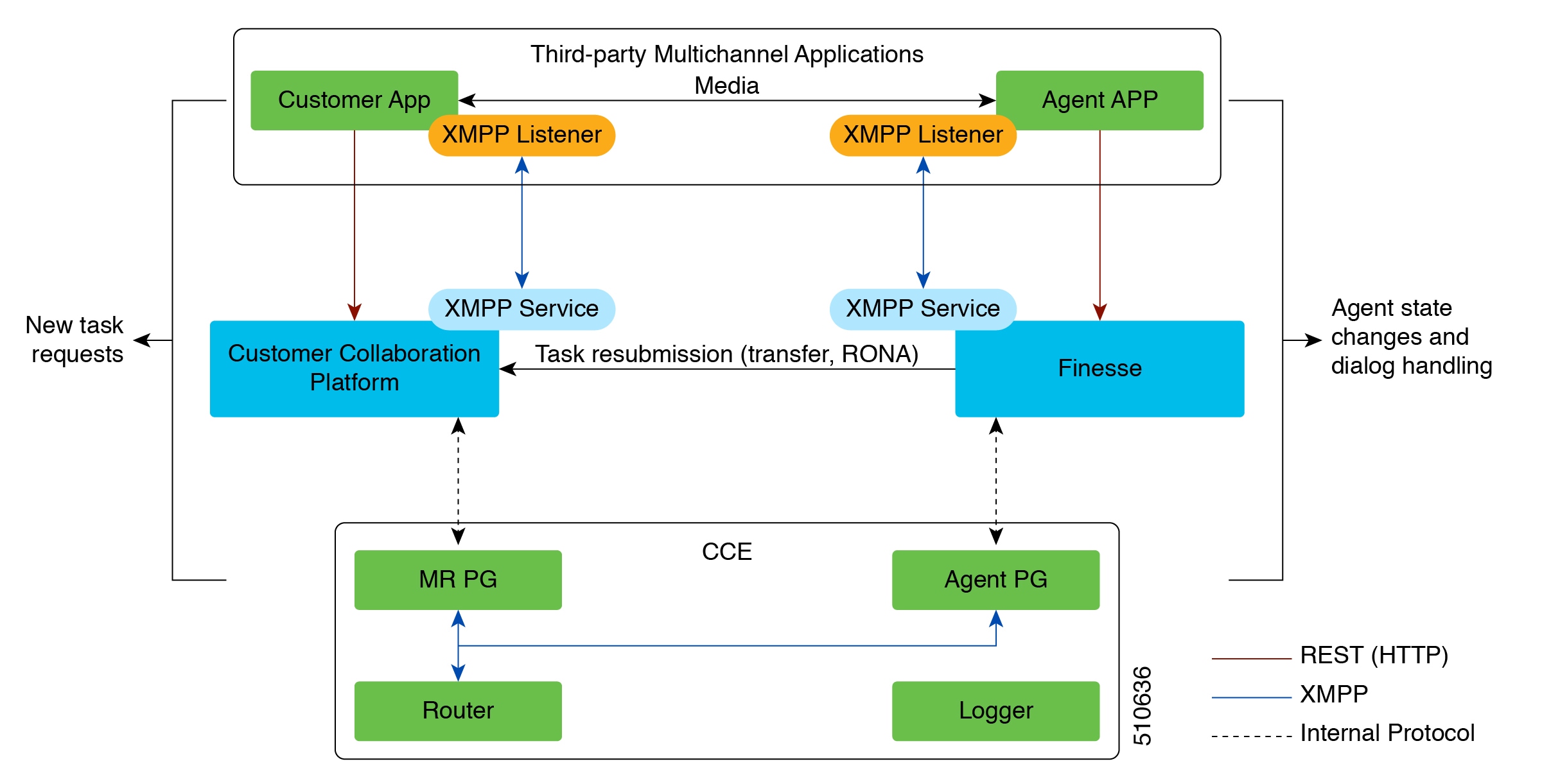


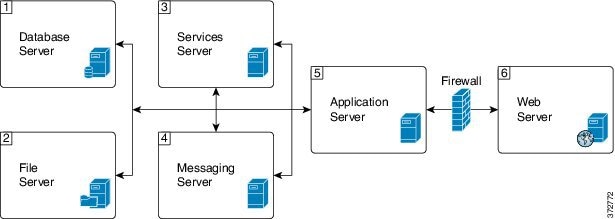


 Feedback