Scripting and Media Routing Guide for Cisco Unified ICM/Contact Center Enterprise, Release 12.6(1)
Bias-Free Language
The documentation set for this product strives to use bias-free language. For the purposes of this documentation set, bias-free is defined as language that does not imply discrimination based on age, disability, gender, racial identity, ethnic identity, sexual orientation, socioeconomic status, and intersectionality. Exceptions may be present in the documentation due to language that is hardcoded in the user interfaces of the product software, language used based on RFP documentation, or language that is used by a referenced third-party product. Learn more about how Cisco is using Inclusive Language.
You can use routing scripts to divert a call to a Network VRU for
additional call processing.
A VRU, or Voice
Response Unit, is a telecommunications device, also called an Interactive Voice
Response Unit (IVR), that plays recorded announcements and responds to
caller-entered touch-tone digits. Cisco Unified Customer Voice Portal (CVP) is
the supported VRU for Packaged CCE. A VRU can also be equipped with Automatic
Speech Recognition (ASR) or Text-to-Speech (TTS) capabilities.
Network VRU Functionality
A Network VRU supports the Unified ICM's service control interface. A Unified
ICM routing script can divert a call to a Network VRU and instruct the VRU
to perform specific processing before the Unified ICM determines the final
destination for the call.
VRU Configuration
You configure Network VRUs through Unified ICM Configuration Manager.
Following are the general steps you must take to configure VRUs before you
can write routing scripts. There are different Network VRU types. Each type
represents a different architecture and call flow. These are summarized
below and described in detail in the Configuration Guide for Cisco Unified ICM/Contact Center Enterprise. Before you can write routing scripts, you must do the
following through the Unified ICM Configuration Manager:
Procedure
Step 1
Configure the Network VRU.
Step 2
Associate the Network VRU with a Network VRU Label.
Note
This step is required for Type 3, Type 5, and Type 7
VRUs.
Step 3
Depending on the type of Network VRU configured, you need to configure various
additional items.
Step 4
Configure Network VRU scripts.
Note
You create and maintain VRU scripts on the VRU; however, you
must define these scripts through the Unified ICM Configuration Manager so that Unified
ICM is aware of these scripts so they can be called from Unified ICM
routing scripts.
Network VRU Types
and Script Nodes
Before a routing
script can run a Network VRU script or queue a call at a Network VRU, it may
require an explicit node to force the routing client to connect the call to the
Network VRU. The node used to send the call to the Network VRU depends on the
Network VRU type, as shown in the following table:
Table 1. Network VRU
Types
Type
Description
Routing
Script Node to Use to Send Call to VRU
2
A Network
VRU at the customer premises. In a NAM environment, a Type 2 VRU is connected
at Unified ICM and not at the NAM: Unified IP IVR in a
Unified CCE solution.
Translation
Route to VRU
3
A Network
VRU connected to a NAM where there is a separate routing client that controls
the connection to the VRU. Use this type rather than Type 7 when the routing
client can automatically take back the call from the VRU when Unified ICM
returns a destination.
Send to VRU
5
A Network
VRU that is controlled by the routing client. Use this type (rather than a Type
3 or Type 6) when the routing client has access to multiple VRUs.
Send to VRU
6
A Network
VRU that receives the call and then sends a route request to Unified ICM.
Send to VRU
7
A Network
VRU controlled by the routing client. Note: Use this type (instead of Type 3)
when the routing client cannot take back the call from the VRU. That is,
Unified ICM automatically instructs the VRU to release when it sends a route
response to the routing client: Cisco Internet Service Node using a Cisco
IOS-based Voice Browser.
Send to VRU
8
Similar to
Type 2, but a Type 8 VRU is used when the NAM has a routing client that
controls the call to the VRU.
Translation
Route to VRU
9
Used for self-service / queuing at IP-IVR when using a System PG, typically in a Parent-Child deployment.
Send To VRU
10
Simplifies configuration requirements in Unified CVP Comprehensive Model deployments. Use this type for calls that need to
be transferred to Cisco Unified Customer Voice Portal (Unified CVP) for self-service or queuing.
Send To VRU
Translation Route to VRU
Access to VRU Scripts in Unified ICM Scripts
After you set up VRUs through the Configuration Manager, you can write routing scripts that send calls to the VRU, queue the
call, and invoke specific VRU scripts.
Send Call to a VRU
with Send to VRU Node
You can send a call to a VRU for further processing by using the Send to VRU node (in the Queue tab of the Palette).
Figure 1. The Send to
VRU Icon
The Send to VRU node is also valid for use with Type 3, Type 5, Type 6, Type 7, and Type 10 VRUs.
When Unified ICM
runs a Send to VRU Node, it looks up the call's Dialed Number, the Dialed Number's Customer, and the Customer’s Network
VRU. If that fails to retrieve a Network VRU, the router uses the system default Network VRU.
If the Network VRU is of Type 3 or Type 7, the router sends an instruction to the routing client to connect the call to the
Network VRU. The instruction contains the label configured for this Network VRU as well as a correlation ID to allow the router
to uniquely identify the dialog with the routing client and the dialog with the VRU PG. The router waits until it receives
a RequestInstruction message from one of the connected VRU PGs with the same correlationID as a sign that the call is now
connected to the VRU.
If the Network VRU is of Type 5 the router sends an instruction to the routing client to connect the call to a VRU resource.
The instruction contains the label configured for this Network VRU. The router waits for a response back from the routing
client that the call is properly connected to the VRU resource.
If the Network VRU is of Type 10 (which is typically used only with Unified CVP), the Router uses a two-step transfer. The
first transfer is to move the call to the Unified CVP, followed by a second automatic transfer to setup a VRU leg for the
call that employs the VXML Gateway or Cisco Virtualized Voice Browser (VVB) for IVR treatment. The purpose of Type 10 VRU
is to simplify the configuration needed in the Comprehensive Call flow model.
Important points to note while you are using the Type 10 network VRU are:
For calls originating from Unified CM, the Correlation ID is automatically added to the end of the transfer label defined
in the Type 10 Network VRU configuration.
For calls that are front-ended or originating from Unified CVP, only a single automatic transfer from the switch leg to the
VRU leg occurs, using the transfer label defined for the Type 10 Network VRU.
For calls originating from all other routing clients like TDM ACD's, other VRU's or NIC's, a "Translation Route to VRU" node
should be employed for the first phase of transfer, instead of the "SendToVRU" node without which the calls would fail.
There are two
failure cases:
If the label
does not exist, script execution continues with control flowing through the
nodes failure output terminal.
If Unified ICM
does not receive confirmation, execution continues with control flowing through the nodes failure output terminal.
In all other cases
script execution continues with control flowing through the nodes success
output terminal.
Notes:
If the Run External Script, Play, Menu, Collect Data, or Queue node is used in a script before a Send To VRU node, an implicit
Send To VRU node is assumed. For Network VRUs of Types 3, 5, 6, or 7 you do not have to use the Send To VRU node. However, include the node in routing scripts as a visual aid if you ever need
to troubleshoot the script.
If the call is delivered to the VRU but then abandoned, script execution ends. In monitor mode, a special label on the Send To VRU node accounts for these cases.
You do not need to
set properties for the Send to VRU node. However, you can optionally add
comments or connection labels.
Send Call to a VRU with Translation Route to VRU
For Type 2 and Type 8 VRUs, you can send a call to a VRU by using the Translation Route to VRU node (in the Queue tab of the
Palette).
Figure 2. The Translation Route to VRU Icon
When Unified ICM uses the translation route to VRU method to route a call to a Type 2 SCI VRU, the VRU becomes the new routing client (dynamic
routing client) for the call. This means that the next Connect message is sent to the VRU from the CallRouter to connect the
call (to an agent, for example).
To transfer a call to CVP using the Translation Route scheme, you must use the CVP DNIS API to configure DNIS numbers in the
CVP call server. For more information, see the CVP Dialed Number Identification Service API chapter in the Cisco Packaged Contact Center Enterprise Developer Reference guide.
Note
For the dynamic routing client feature to work, the routing target (network VRU, services, and so on) needs to have labels
configured for the type 2 VRU as a routing client.
This feature is applicable for following call scenarios:
Receiving a call on a converged enterprise network after a carrier pre-route using Unified CVP to control the call.
Supporting Outbound Option for Unified CCE where a shared Network VRU is used for providing announcements to targeted phones/answer
machines.
Using pre-routing for load balancing purposes before the call is sent to a Unified CVP controlled network, with call context
and cradle to grave reporting capabilities.
In an environment where the routing client is not capable of Network Transfer all the pre-route calls must be transferred
to Unified CVP by a Translation Route To VRU to take advantage of network transfer feature.
Typical Call Flow Example:
A call is pre-routed by Unified ICM using a carrier NIC to a Type 2 premise VRU using the TranslationRouteToVRU mechanism. The VRU becomes the new routing client.
When the VRU is done with the call, the script connects the call to an agent on a TDM ACD (using translation routing again)
and the VRU connects the call to the agent.
The agent answers the call and talks to the caller.
The agent initiates a transfer and the script and configuration initiate a network transfer. The Connect message is sent to
the Type 2 VRU, and the VRU connects the call to the new destination.
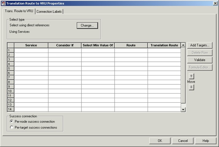
Following is the Properties dialog box for the Translation Route to VRU node:
Figure 3. Translation Route to VRU Properties
Define Translation Route to VRU node properties as follows:
Procedure
Step 1
To change the type of target:
Click
Change. The Select Type dialog box opens.
Choose the Target Type (Enterprise Service, Service, or
Service Array).
If you selected Enterprise Service, select a
Business Entity and
Enterprise target.
Specify whether the Translation Route to VRU node is to act
like a Select or Distribute node.
Distribute Among Targets. The
Translation Route to VRU node is to act like a Distribute node, distributing
calls among the targets based on the relative values.
Select Most
Eligible Target. (Radio button.) The Translation Route to VRU node is to act
like a Select node.
If you select this option, you:
Define whether to pick the target with the maximum value or
the minimum value.
Define a formula that determines which target is to be
accepted.
Define the type of target search.
Step 2
To add targets, click
Add Targets. The Add Targets dialog box opens. Use the
Available Targets list and the Add button to select targets.
Note
If you
choose Enterprise Service as a target type, you can select just one item from
the list. If you choose Service or Service Array, you can select one or more
items from the list.
Step 3
Click
OK to close the Add Targets dialog box. The target members you
selected appear in the Properties dialog box.
Step 4
Continue defining Target information for each target:
Consider If (Optional.) A formula that must evaluate to true for the target when the Unified ICM initiates the Translation Route to VRU node, or that target is not considered.
Select Max/Select Min Value of A formula that determines which of the targets is selected.
(Drop-down list.) The route on which to send the call if you select this target. (The list contains all routes associated
with the target.)
Translation Route (Drop-down list.) The route to send the call for initial VRU processing if you select this target. (The list contains all
translation routes associated with the same peripheral as the target.)
Note
You must specify a value for this field. When a call is sent to a translation route, the PG retrieves the final route from
the Unified ICM and coordinates the other processing with the VRU.
Per-node success connection(Radio button.) Select this option to attach one success output terminal to the node. This terminal is used regardless of
which target you select.
Per-target success connection (Radio button.) Select this option to attach a success output terminal to each target in the node.
Note
This option is useful in situations where you want to use different scripts depending on the selected target for a call.
Step 5
Optionally, click
Validate to validate the node properties.
Step 6
Optionally, add connection labels.
Send Call to a VRU after Translation Route to VRU
A SendToVRU node first checks for the Dialed Number. If the Dialed Number
is not configured, the node immediately fails, interrupting the dialog. If
the Dialed Number is configured, the node checks for the Customer. If the Customer is not defined, the node tries to send
the call to
Default Network VRU.
If the Customer is defined, the SendToVRU node sends the
call to the Customer's Network VRU. If the node cannot identify the Customer Network VRU, the
node sends the call to the Default Network VRU.
An explicit SendToVRU node only exits if the call is at the
specified VRU, for example, the dialed
number's customer Network VRU. If the call is at the wrong VRU, the node transfers the call to the correct VRU.
Example Call Flows:
A call is moved to a Type 2 VRU via a Translation Route to VRU. The SendToVRU node moves the call to a Type 3 VRU if the Type
3 VRU is configured to be the network VRU for this call.
A call arrives from a Type 6 VRU. SendToVRU attempts to send the call to the configured network VRU if the network VRU is
different from the routing client’s VRU.
SendToVRU fails the node if the transfer to the
network VRU fails.
If the configuration is wrong or missing, (for example, if a network VRU is not defined, or proper label is not defined) then
the fail path is run and the call remains at the VRU.
If the CallRouter succeeds in sending a Connect message,
the CallRouter resets the previous VRU information and waits
for RequestInstruction to set up the new VRU connection. If
the operation times out, (RequestInstruction never arrives),
then the fail path of the SendToVru node is taken and the
call is assumed not to be at a VRU. The same behavior
applies if CallRouter receives a ReRoute instead of a
RequestInstruction command.
A registry flag enables/disables this feature. The registry key is
called NetworkVRUCheckEnabled and is located at
...\Router\CurrentVersion\Configuration\Global.
The default value is 1 (enabled), setting it to 0 disables
it.
Run External
Scripts
You can instruct a Network VRU to run a specific script by using the Run External Script node (in the Queue tab of the Palette).
Figure 4. The Run External Script icon
You can use multiple Run External Script nodes to run a series of scripts on the VRU.
The Run External Script node is valid for use with all the VRU types.
Note
When you integrate the ECE with the Unified ICM, you can also use the Run External Script node to push a URL to the caller's web browser. To do this,
an entry in the Network VRU list must point to the URL map file on the ECE. For more information, see the Configuration Guide for Cisco Unified ICM/Contact Center Enterprise.
The execution of Unified ICM
routing script waits for the external script to finish:
If the external script runs successfully, control then passes through the success branch of the Run External Script node.
If the external script does not run successfully for any reason, then control passes through the failure branch of the Run
External Script node.
Note
If the current call is not at a VRU when the Run External Script node is run, Unified ICM
sends the call to the associated Network VRU, as run a Send to VRU node.
Design scripts so that the Failure branch of a Run External Script Node contains a test for the Call.VRUStatus variable. If
the value is 2, the VRU is likely to be not functioning properly. Therefore, the script avoids executing any subsequent Run
External Script nodes on this Failure branch.
Note
When an uninterruptible script is used in a Run External Script node, the CallRouter waits for the script result from the
VRU. It then runs the next node. Calls can only be routed when they reach an interruptible node. The Wait node and interruptible
Run External Script node ( micro apps) are interruptible. Every other node is uninterruptible.
Following is the Properties dialog box for the Run External Script node:
Figure 5. Run External Script Properties
Define Run External Script node properties as follows:
Procedure
Step 1
Select the Unified ICM
Script/External Script Name you want to run.
Step 2
Optionally, add
comments and connection labels.
VRU Errors
The following table lists the possible values for the VruStatus variable:
Table 2. VruStatus Variable Codes
Value
Meaning
Description
0
VRU_SUCCESS
The last VRU node was successful.
1
VRU_ERROR
The last VRU node failed because of a routing or
configuration error.
2
VRU_TIMEOUT
The last Send To VRU or Translation Route to VRU node failed because the routing client did not respond within 20 seconds or the last Run External Script node failed because the
timeout limit defined for the script expired.
3
VRU_ABORTED
The last VRU node did not complete because the caller ended the call or stopped responding. (Because this causes the routing
script to terminate immediately, this value is never seen.)
4
VRU_DIALOG_ FAILED
The last VRU node failed because communication with
the VRU ended unexpectedly.
5
VRU_SCRIPT_ NOT_FOUND
The VRU failed because the referenced VRU script was not found in the Unified ICM
configuration.
6
STATUS_MAX_QUEUE_LIMIT_EXCEEDED
The last node failed because the maximum call queuing limit was exceeded.
7
STATUS_NO_VALID_EXPRESSION
The last node failed because no valid expression was found.
8
STATUS_NO_VALID_TARGET
The last node failed because no valid target was found.
10
STATUS_NO_MRD_MATCH
The last node failed because no targets matched with the Media Routing Domain on the call.
11
STATUS_CONSIDER_IF_FAILED
The last node failed because the Consider If expression failed on all targets.
12
STATUS_NO_VALID_PERIPHERAL
The last node failed because none of the targets were configured on the supported peripheral.
13
STATUS_NO_ONLINE_PERIPHERAL
The last node failed because all targets are on peripherals that are offline.
Call Queuing at
VRUs
You can queue a call at a Network VRU until a specific resource becomes available. A call can be queued for one or more skill
groups, an enterprise skill group, a precision queue, or one or more scheduled targets. As soon as an agent becomes available at one of the specified targets, the call is removed from the queue and sent to the
target.
Specifically, you
can:
Place a call in
a precision queue.
Place the call in one or more skill groups, an enterprise skill group, or one or more scheduled targets.
Adjust the priority of call in a queue for one or more skill groups or scheduled targets.
Remove the
current call from any queues to which it is assigned.
Call Flow:
The call is
first sent to the Network VRU. This step is required before you queue the call.
The call is
queued for three skill groups.
If the call is successfully queued, the script cycles between a Wait node and a Run External Script node so that the caller
hears an announcement every 30 seconds.
If an agent in one of the skill groups becomes available, the call is removed from queue and taken back from the a VRU . Routing script execution ends and the call is delivered to the target.
You could use other nodes like Queue to Skill Group or Queue to Precision Queue to queue the calls to different targets.
Caution
Do not use the nodes like Route Select to queue the calls when the script cycles between a Wait node and a Run External Script
node.
Note
In this scenario,
you would likely make the VRU script interruptible so that the routing script
can retrieve the call immediately when the resource becomes available.
Place a Call in Queue
You can place a call in queue at a VRU for one or more skill groups, enterprise skill group, or one or more scheduled targets
using the Queue node (in the Queue tab of the Palette).
Figure 6. The Queue Icon
If an agent becomes available in one of the skill groups or at one of the scheduled targets, the call is routed to that resource.
Note
If the current call is not at a VRU when the Queue node is run, the Unified ICM sends the call to the associated Network VRU.
(This does not apply to Type 2 or Type 8 VRUs, which are VRUs at customer premises.)
You cannot reference two types of targets (for example, skill groups and scheduled targets) within a single Queue node. However,
you can run multiple Queue nodes sequentially to queue a call to different target types.
The Queue node includes a Priority field, which sets the initial queuing priority for the calls processed through this node versus other calls queued for the
same target. The priority is expressed as an integer from 1 (top priority) to 20 (least priority). The default value is 5.
If more than one call is queued to a group when an agent becomes available, the queued call with the lowest priority number
is routed to the target first. For example, assume an agent in a skill group becomes available and two calls are queued to
that skill group. If one call has priority 3 and the other has priority 5, the call with priority 3, the lower value, is routed
to the skill group while the other call continues to wait.
Note
The Queue node does not actually result in instructions being sent to the VRU. When queuing occurs the Queue node exits immediately
through the success branch and the call is assumed to be at the VRU; the script should then continue with a Run External Script
node to instruct the VRU what to do while holding the call until an agent to becomes available. Typically this would invoke
a Network VRU script that plays music-on-hold, possibly interrupted on a regular basis with an announcement.
Following is the Properties dialog box for the Queue node:
Figure 7. Queue to Skill Group Properties
Define Queue node properties as follows:
Procedure
Step 1
To change the queue type:
Click Change. The Queue Type dialog box opens.
Select a Target Type (Enterprise Skill Group, Scheduled Target, or Skill Group). You cannot reference more than one type of target within a single Queue node. To queue a call to more than one
target type, run multiple Queue nodes sequentially.
Optionally, select a Business Entity and Enterprise Target.
Optionally, select a Priority to set the initial queuing priority for calls processed through this node versus other calls
queued for the same target: 1 for top priority to 20 for least priority. (The default is 5.)
Optionally, check Enable Target Requery.
Note
When Target Requery is enabled in a Queue node and a Requery happens, for example because the call is presented to an available
agent, but the agent does not answer, the script continues through the failure terminal. The script can then inspect the call
variable RequeryStatus to determine what to do next. The typical action in case of a No Answer would be to Queue the call
again, possibly to other skill groups, and possibly increase the priority so that it is taken out of the queue before regular
queued calls.
Click OK to close the Queue Type dialog box.
Step 2
To add targets:
Click Add Targets. The Add Targets dialog box opens, listing available targets of the type you specified.
Use the Available Targets list and the Add button to select targets.
Click OK to close the Add Targets dialog box. The target members you selected appear in the Properties dialog box.
Step 3
Optionally, continue defining Target Type information foreach target member:
Route. (Drop-down list.) The route to send the call to when an agent in the target type becomes available. (The drop-down
list includes all routes associated with the target.)
Translation Route. (Drop-down list.) The route to send the call for initial VRU processing if you select this target. (The
list contains all translation routes associated with the same peripheral as the target.)
Scheduled Target. Individual targets to which the call is queued, if the Target Type is Scheduled Target.
Step 4
Optionally, add connection labels.
What to do next
Note
When processing a Queue node, the router first checks for an available target, if there is none available then the router
attempts to queue the call. The call does not move to the VRU if there is an available agent.
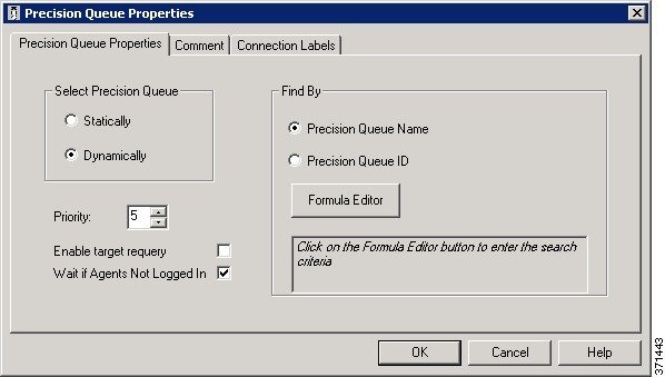
Precision Queue
Script Node
You can use the Precision Queue script node to queue a call or task based on caller requirements until agents with desired
proficiency become available. This node contains multiple agent selection criterion which are separated into steps.
Figure 8. Precision
Queue Script Node
A single call can be queued on multiple precision queues. If an agent becomes available in one of the precision queues, the
call is routed to that resource. You cannot reference multiple precision queues with a single Precision Queue node. However,
you can run multiple Precision Queue nodes sequentially to achieve this.
The Precision Queue node includes a Priority field, which sets the initial queuing priority for the calls processed through this node versus other calls queued to the
other targets using different nodes. The priority is expressed as an integer from 1 (top priority) to 20 (least priority).
The default value is 5.
If more than one
call is queued to a precision queue when an agent becomes available, the queued
call with the lowest priority number is routed to the target first. For
example, assume an agent in a precision queue becomes available and two calls
are queued to that precision queue. If one call has priority 3 and the other
has priority 5, the call with priority 3, the lower value, is routed to the
precision queue while the other call continues to wait. If the priorities of
the two calls are same, then the call queued first is routed first.
VRU script
instructions are not sent to the VRU. If a call enters the Precision Queue node
and no resource is available, the call is queued to the precision queue and the
node transfers the call to the default VRU, if the call is not already on a
VRU. The script flow then exits immediately through the success branch and
continues to a Run External Script node to instruct the VRU what to do while
holding the call until an agent becomes available. Typically, this invokes a
Network VRU script that plays music-on-hold, possibly interrupted on a regular
basis with an announcement. The script flow can also use other queuing nodes to
queue the same call to other targets, for example, Queue to Skill Group and
Queue to Agent.
The following property
is unique to static precision queues:
Drop-down list—To route
calls that enter this node to a static precision queue, you must select a
precision queue from the list.
The following
properties are common to static and dynamic precision queues:
Select Precision Queue radio
buttons—You can select one of the following options for each a precision
queue:
Statically—Select this
option to choose a single precision queue to be selected for all the calls that
enter this node.
Dynamically—Select this
option to select a precision queue on a call-by-call basis based on a formula.
Note
Dynamic Precision Queue selection is not available when an External Authorization server is used with Internet Script Editor
and will be grayed out in the interface.
Priority selection—To select the initial queuing priority for calls processed through this node, you can select from 1 to 20. The default is
5.
Enable target requery check
box—To enable the requery feature for calls processed through this node,
select this check box. When a requery occurs, for example if a call is
presented to an available agent and the agent does not answer, the script
continues through the failure terminal. The script can then inspect the call
variable RequeryStatus to determine what to do next. The typical action in case
of a No Answer is to queue the call again to other precision queues, and
increase the priority so that it is taken out of the queue before regular
queued calls.
Wait if Agents Not Logged In check box — When this check box is selected and the agents who are associated with a step are not logged in, then the router will wait
for the time that is configured for that step. When this check box is not selected, the router will not wait on any step.
However, on the last step, the router will wait indefinitely irrespective of the selection.
The following list
describes the Precision Queue Properties dialog box for a dynamic precision
queue script node.
Use dynamic precision
queues when you want a single routing script for multiple precision queues (for
example, when the overall call treatment does not vary from one precision queue
to another). Dynamic precision queues can simplify and reduce the overall
number of routing scripts in the system.
Dynamic Precision Queue selection is not available when an External Authorization server is used with Internet Script Editor
and will be grayed out in the interface.
The following
properties are unique to dynamic precision queues:
Find By radio buttons—To
dynamically route calls that enter this node to a Precision Queue name or ID,
use the Find By radio buttons.
Precision Queue Name
radio—Select this option to dynamically route calls that enter this node to
a Precision Queue name.
Precision Queue ID—Select
this option to dynamically route calls that enter this node to a Precision
Queue ID.
Formula Editor button—To determine to which Precision Queue name or ID to route calls that enter this node, click the Formula Editor button to
create a formula. The formula is then evaluated at run time to select a precision queue by either name or by database ID.
For example, you can use the formula "Call.PeripheralVariable4" to look up the Precision Queue if call variable 4 contained
the Precision Queue name, as a result of a database lookup or from VRU call processing.
Note
The section on static precision queues describes the properties that are common to static and dynamic precision queues.
Queuing Behavior of
the Precision Queue Node
Precision queues internally are configured with one or more time-based steps, each with a configured wait time. After a call
is queued, the first step begins and the timer starts. This occurs although the path of the script exited the success node
and a new node may be targeted (for example, Run Ext. Script).
If the timer for the first step expires, control moves to the second step (assuming one exists), and so on. As long as the
call remains in queue and there are steps left to perform, the call internally continues to move between steps regardless
of the path the call takes after it leaves the precision queue node. If a call is queued to two or more precision queues,
the call internally walks through the steps for each precision queue in parallel. After the call reaches the last step on
a precision queue, it remains queued on that step until the call is routed, abandoned, or ended.
If there is an update to the precision queue definition, then all queued calls in the precision queue are re-evaluated and
are re-run from the first step.
For example, consider the wait time for an ongoing call at step 1 to be 1080 seconds, of which 1000 seconds has already elapsed.
Now, suppose the wait time is changed to 900 seconds, then the wait time for this call is also reset to 900 seconds, even
though only 80 more seconds are left to move to the next step.
Adjust Priority of a Call in a Queue
You can override the priority of a call in queue set by the Queue node by
using the Queue Priority node (in the Queue tab of the Palette).
Figure 11. The Queue Priority Icon
For example:
The original priority of the call in queue is set by the Queue to
Skill Group node or the Precision Queue node.
The call waits in queue for 20 seconds while the caller listens to
an announcement.
Call control passes to a second Wait node.
If 20 more seconds pass without an agent becoming available, the Queue Priority node is run and raises the call's priority
in queue.
Notes:
Only use the Queue Priority node after a Queue to Skill Group node or a Precision Queue
node. Any subsequent use of the Queue to Skill Group node or the Precision Queue node results in
setting the queue priority back to the original setting for that node.
The Queue Priority node sets the priority for a call within all
queues that the call is placed in. If a call requires the
priority to be raised in one queue only, you should use a subsequent Queue to Skill Group
or Precision Queue node for only that skill group/queue (with the new priority).
Queuing priorities should be handled very carefully. Just increasing Queue priority does not get a call handled sooner. The
effect depends on the other call in the queue. For example, if all calls are treated using the example above, the priority
increase has no net effect. If the script above is only used for the Platinum customers while the Standard customers script
leaves them at the default priority level, the effect is that all Platinum customers that have been in queue for more than
20 seconds are handled first regardless of other customers in queue. As the delay for Platinum customers is greater than 20
seconds, no Standard customers are handled ever. The solution is to increase the priority level for Standard customers as
well, but only after they have been in queue for a longer period, for example 3 minutes.
Following is the Properties dialog box for the Queue Priority node:
Figure 12. Queue Priority Properties
Remove Call from a Queue
You can remove a call from any queues by using the Cancel Queuing node (in
the Queue tab of the Palette).
Figure 13. The Cancel Queuing Icon
You do not have to define properties for the Cancel Queuing node. You can
optionally add comments or connection labels.
VRU MicroApp Nodes
Note
You can only use these nodes if supported by your VRU.
The three VRU MicroApp nodes (Collect Data, Menu, Play) are essentially
specialized Run External Script nodes. They allow you to specify all details of the
interaction in the script node, rather than using
the Unified ICM Configuration Manager to specify the
Network VRU Script.
The three MicroApp nodes each represent a specific sort of VRU
interaction:
Collect Data instructs the VRU to collect data from a caller after
playing a prompt. The prompt can be played using a recorded
announcement or using TTS. The data collected can be collected using
touch-tone or using Automatic Speech Recognition (ASR).
Menu is a simplified form of Collect Data that instructs the VRU
to build a menu. It prompts the caller (either using a recorded
announcement or TTS) and collects a single digit (either using touch
tone or ASR). At the Menu node the script branches, depending on the
input from the caller.
Play instructs the VRU to speak a recorded announcement or a data
element, such as a number or date. This can be done either by using
recorded announcements or through Text-to-Speech (TTS) capabilities.
Collect Data From Caller
You can have a script play a prompt and instruct the caller to enter information by using the Collect Data node (in the Queue
tab of the Palette) . The caller-entered data can then be used to redirect the call to the appropriate destination.
Figure 14. Collect icon
Following is the Properties dialog box for the Collect Data node:
Figure 15. Collect Data Properties
Define Collect Data node properties as follows:
Procedure
Step 1
In the File Name field, enter the name of the media file to be
played to the caller.
Step 2
In the Library drop-down list, select the location of
the file. You can select:
System
Application (default)
None
Step 3
In the Protocols drop-down list, select the data
transmission convention to use for the media file contents. You
can select:
HTTP: (Hypertext Transfer Protocol, the default)
RSTP: (streaming)
file:
other
Step 4
Specify the number of digits a caller can enter:
In the Minimum number of digits field,
select a number from 1 to 32 to indicate the minimum number
of digits the caller must enter. The default is 1.
In the Maximum number of digits field,
select a number from 1 to 32 to indicate the maximum number
of digits the caller must enter. The default is 1.
In the Termination key field, enter the
key that the caller presses to signify the end of digit
entry. Value options are the digits 0-9, # (pound, the
default) or * (asterisk). For variable-length data entry,
only. A key that the user presses to signify the end of
digit entry. Valid options: The digits 0-9, # (pound, the
default) or * (asterisk).
Note
If the minimum number value equals the maximum number
value, this field is grayed out.
Step 5
Optionally, check Use ASR to use
automatic speech recognition. If you check this option:
Caller-entered information is obtained from spoken input
as well at DTMF entry.
In the Automatic speech recognition
grammar text box, enter a grammar against which
caller spoken-input is matched.
Step 6
Optionally , check Allow barge-in to have any
digit entry by the caller interrupt the media playback. Unified CVP deals with barge-in as follows: If barge-in is not
allowed (not checked), the Voice Browser continues to prompt play
when a caller starts entering digits. If barge-in is allowed
(checked), the Voice Browser discontinues prompt play when the
caller starts entering digits.
Step 7
Optionally, click Advanced Properties to specify
how the micro-application should handle invalid or timed-out
entries.The Advanced Properties override the VRU Default settings
configured in the Unified ICM configuration database. The values you set
apply only to the current node; other Collect Data nodes are not
affected. Initial values for timeouts and number of tries on this dialog
box show the current values, obtained either from the database defaults
or from a VRU Settings node. Invalid entry and No entry Media file names may be
defined on the VRU device and invisible to Unified ICM
environment. If this is the first micro-application operation in
the script, the value for these fields is Default; it remains
this value unless a VRU Settings micro-application changes
it.
Optionally, clear Unified ICM may interrupt. When checked
(the default), the operation of the node can be interrupted
by the router.
Optionally, clear Inter-digit timeout. When checked (the
default), enter the number of seconds allowed between
entering digits before the system assumes the caller is
finished. Valid options: 1-99, default: 3.
In both the Invalid Entry Media Properties and No Entry
Media Properties sections, enter the file names of the files
to play if the caller enters invalid data or if the caller
enters no data.
Note
To use the default settings on the VRU device, enter the
word Default in these fields.
Select the locations of the files in the Library drop-down
lists. Valid options: System, Application (default),
None.
Note
If None, include the full path file name
in the File name value; for example:
http://www.xyzcorp.com/Media_Folder/File.wav.
Select the data transmission convention to use in the
Protocol drop-down lists. Valid options: HTTP: (Hypertext
Transfer Protocol, the default), RSTP: (streaming), file:,
other.
Enter a number in the Number of tries field to indicate
the number of times the Collect Data or Menu MicroApp queries the user for data when the user enters invalid data or
does not enter data. Valid options: 1-9 (default: 3).
Note
Optionally, you can clear the check box to have the
default value defined in the database used.
In the No Entry Media Properties section,
enter a number in the Timeout field to indicate the number
of seconds a caller is allowed to begin entering digits. If
exceeded, the system times-out. Valid options: 1-99,
default: 5.
Note
If not checked, the default value defined in the database
is used.
When you have finished specifying advanced properties,
click OK.
Step 8
Optionally, add comments or connection labels.
Prompt Caller to Select from a Set of Options
You can have a script play a prompt and instruct the caller to select from
a list of options using the Menu node ( in the Queue tab of the Palette).
Figure 16. The Menu Icon
You can then use the caller-entered data to redirect the call to the
appropriate destination.
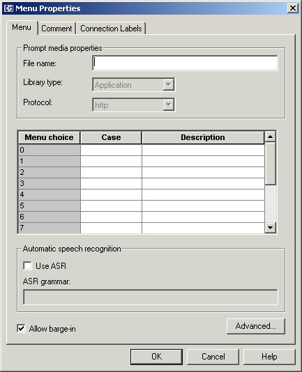
Following is the Properties dialog box for the Menu node:
Figure 17. Menu Properties
Note
You must define one or more success connections from the Menu node before
you can define Menu node properties.
Define Menu node properties as follows:
Procedure
Step 1
In the File Name text box, enter the name of the
media file to be played to the caller.
Step 2
In the Library drop-down list, select the location of
the file. You can select:
System
Application (default)
None
Step 3
In the Protocols drop-down list, select the data
transmission convention to use for the media file contents. You
can select:
HTTP: (Hypertext Transfer Protocol, the default)
RSTP: (streaming)
file:
other
Step 4
Define menu choices. For each row beginning with the
possible caller entered digit (which you cannot edit):
In the Case column, select a number from
the drop-down list. The available numbers correspond to the
success branches from the Menu node. The number indicates
that if the caller enters the digit in that row, the call
processing continues down that success branch.
Enter a description from the selected menu choice.
Step 5
Optionally, check Use ASR to use
automatic speech recognition. If you check this option:
Caller-entered information is obtained from spoken input
as well at DTMF entry.
In the Automatic speech recognition
grammar text box, enter a grammar against which
caller spoken-input is matched.
Step 6
Optionally , check Allow barge-in to have any
digit entry by the caller interrupt the media playback.
Note
The Unified CVP deals with barge-in as follows: If barge-in is not
allowed (not checked), the Voice Browser continues to prompt play
when a caller starts entering digits. If barge-in is allowed
(checked), the Voice Browser discontinues prompt play when the
caller starts entering digits.
Step 7
Optionally, click Advanced Properties to specify
how the micro-application should handle invalid or timed-out
entries. The Advanced Properties override the VRU Default settings
configured in the Unified ICM configuration database. The values you set
apply only to the current node; other Collect Data nodes are not
affected. Initial values for timeouts and number of tries on this dialog
box show the current values, obtained either from the database defaults
or from a VRU Settings node. Invalid entry and No entry Media file names may be
defined on the VRU device and invisible to Unified ICM
environment. If this is the first micro-application operation in
the script, the value for these fields is Default; it remains
this value unless a VRU Settings micro-application changes
it.
Optionally, clear Unified ICM may interrupt. When checked
(the default), the operation of the node can be interrupted
by the router.
Optionally, clear Inter-digit timeout. When checked (the
default), enter the number of seconds allowed between
entering digits before the system assumes the caller is
finished. Valid options: 1-99, default: 3.
In both the Invalid Entry Media Properties and No Entry
Media Properties sections, enter the file names of the files
to play if the caller enters invalid data or if the caller
enters no data.
Note
To use the default settings on the VRU device, enter the
word Default in these fields.
Select the locations of the files in the Library drop-down
lists. Valid options: System, Application (default), None.
Note
If None, include the full path file name
in the File name value; for example:
http://www.xyzcorp.com/Media_Folder/File.wav.
Select the data transmission convention to use in the
Protocol drop-down lists. Valid options: HTTP: (Hypertext
Transfer Protocol, the default), RSTP: (streaming), file:,
other.
Enter a number in the Number of tries field to indicate
the number of times the Collect Data or Menu MicroApp queries the user for data when the user enters invalid data or
does not enter data. Valid options: 1-9 (default: 3).
Note
Optionally, you can clear the check box to have the
default value defined in the database used.
In the No Entry Media Properties section, enter a number
in the Timeout field to indicate the number of seconds a
caller is allowed to begin entering digits. If exceeded, the
system times-out. Valid options: 1-99, default: 5.
Note
If not selected, the default value defined in the database
is used.
When you have finished specifying advanced properties,
click OK.
Step 8
Optionally, add comments or connection labels.
Play Specific Recordings to Caller
You can instruct the VRU to play a series of media files and/or data to
the caller by using the Play node (in the Queue tab of the Palette).
Figure 18. The Play Icon
Data can be a literal string or a formula that evaluates to a string. The
data, its type, and the format it is to be played in is sent to VRU as part
of the play request.
Note
The CallRouter does not verify the format setting to see if it is valid
for the specific data type or micro-application. If the data format is
invalid, the micro-application's result code indicates such an
error.
Following is the Properties dialog box for the Play node:
Figure 19. Play Properties
Define Play node properties as follows:
Procedure
Step 1
Click Add to add a new file or data element to
play to the caller.
Step 2
In the pop-up menu, choose Media or Data.
Step 3
If you selected Media in Step 3:
Enter the name of the file to play in the File name field.
In the Library drop-down list, select the location of the
file. You can choose:
System
Application (default)
None
In the Protocols drop-down list, select
the data transmission convention to use for the media file
contents. You can choose:
HTTP: (Hypertext Transfer Protocol, the default)
RSTP: (streaming)
file:
other
Step 4
If you selected Data in Step 3:
In the Data field, enter a string (or a formula that
evaluates to a string) to be played by the VRU.
In the Data type drop-down list, choose the type of data
to be played: Type of data to be played by the VRU. Valid
options are:
Number - Numeric
Char - Character
Etime - Elapsed timeTOD - Time of day (12 hr)
TOD - Time of day
24TOD - Time of day (24 hr)
DOW - Day of week
Date - Entire date
Currency - Money units
Text - text
If you have selected the Etime, TOD, or 24TOD options in
Step b ( in the Time format drop-down list), then you should
select the time format. The valid options are:
HHMM (default) - Hours and minutes
HHMMSS - Hours, minutes, and seconds
HHMMAP (TOD format, only) - Hours and
minutes, A.M. or P.M.
Note
If the minimum number value equals the maximum number
value, this field is grayed out.
Step 5
Optionally, clear the Allow barge-in check box to
not have any digit entry by the caller interrupt the media playback. Unified CVP deals with barge-in as follows: If barge-in
is not
allowed (not checked), the Voice Browser continues to prompt play
when a caller starts entering digits. If barge-in is allowed
(checked), the Voice Browser discontinues prompt play when the
caller starts entering digits.
Step 6
Optionally, clear the ICM may interrupt check box.
When checked (the default), the operation of the node can be
interrupted by the router.
Step 7
Optionally, add comments or connection labels.
Override VRU Settings
You can override a default VRU setting on a call-by-call basis by using
the VRU Settings node (in the Queue tab of the Palette).
Figure 20. The VRU Settings Icon
You can only override one VRU setting with the VRU Settings node; you must
use additional nodes to override additional settings.
Following is the Properties dialog box for the VRU Settings node:
In the VRU Variable list, select the VRU variable to override.
Step 2
Select an option in the Set To field:
Select ICM Configured Setting to have Script Editor set
the variable to the value stored in the VRU_Defaults table,
at runtime.
Select VRU Peripheral Setting to have Script Editor, at
runtime, leave the variable's value as is.
Note
This value might be from the VRU_Defaults table, or
consist of a value defined through a previous VRU Settings
node.
Select Customer Defined Value to have Script Editor, at
runtime, set the variable to the value specified in the New
Value field. If you select this setting, the New Value field opens for
editing. Specify a value in this field. (The variable type
determines the type of data you can enter.)
Step 3
Optionally, add comments or connection labels.
Temporarily Halt
Script Execution
You can halt script execution for a specified number of seconds by using the Wait node (in the Queue tab of the Palette).
Figure 22. The Wait Icon
The Wait node simply stops script executing for the specified number of seconds. In the meantime, the Network VRU is waiting
for instructions.
Warning
You must set protocol time-out variables in the VRU system to a value greater than the longest wait node used in the script.
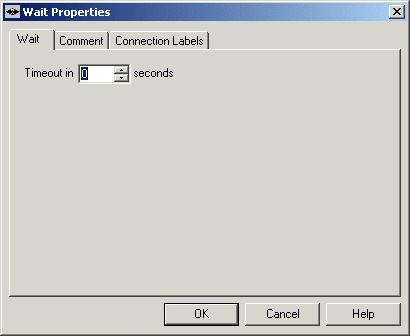
Following is the Properties dialog box for the Wait node:
Figure 23. Wait Properties
Define Wait node properties as follows:
Procedure
Step 1
In the Timeout
in field, specify an interval to wait, in seconds.


 Feedback