Design Considerations for Integrated Features

Agent Greeting Considerations

Consider these points when you add Agent Greeting to your solution:

  • Agent Greeting does not support outbound calls made by an agent. The announcement plays for inbound calls only.

  • Only one Agent Greeting file plays per call.

  • Supervisors cannot listen to agent recorded greetings.

  • Agent Greetings do not play when the router selects the agent through a label node.

  • Agent Greeting supports Unified CM-based Silent Monitoring with this exception: Supervisors cannot hear the greetings themselves. If a supervisor starts a silent monitoring session while a greeting plays, a message appears that a greeting is playing and to try again shortly.

  • Use either G.711 a-law or mu-law for the VRU leg on the Voice Browser dial-peer. Do not use the voice-class codec.

  • In general, Agent Greeting feature requires shorter latency across the system. For example, the public network has a maximum round-trip latency of 100 ms to support Agent Greeting feature as designed.

Agent Greeting requires the following:

  • The phones have the BIB feature.

  • The phones must run the latest firmware version delivered with Unified Communications Manager.

  • The phones must be have BIB enabled in Unified Communications Manager.

Agent Greeting with Whisper Announcement

You can use Agent Greeting with the Whisper Announcement feature. Consider these points when using them together:

  • The Whisper Announcement always plays first.

  • To shorten your call-handling time, use shorter Whisper Announcements and Agent Greetings than if you were using either feature by itself. A long Whisper Announcement followed by a long Agent Greeting equals a long wait before an agent actively handles a call.

  • If you use a Whisper Announcement, your agents probably handle different types of calls: for example, "English-Gold Member-Activate Card," "English-Gold Member-Report Lost Card," "English-Platinum Member-Account Inquiry." Ensure that greetings your agents record are generic enough to cover the range of call types.

Agent Greeting Phone Requirements for Local Agents

Agent Greeting is available to agents and supervisors who use IP Phones with Built-In Bridge (BIB). These agents are typically located within a contact center. Phones used with Agent Greeting must meet these requirements:

Agent Greeting Call Flows

Figure 1. Agent Greeting Call Flow
  1. The incoming call arrives from CUBE or a TDM gateway at CVP.

  2. CVP sends the incoming call to Unified CCE.

  3. Unified CCE instructs CVP to queue the call.

  4. CVP sends the call to the Voice Browser for VRU treatment.

  5. When an agent is available, Unified CCE sends the agent number to CVP.

  6. CVP sends the call to Unified CM.

  7. Unified CM establishes the connection to the agent phone.

  8. The caller connects to the agent phone and stops hearing the ringback.

  9. Unified CCE determines which CVP to invoke, and instructs Unified CM to tell the phone BIB to open a stream to CVP.

  10. Unified CCE and CVP shake hands to set the trigger for CVP to let it know which greeting to play.

  11. CVP instructs the Voice Browser to have the Media Server play the greeting.

  12. The phone's BIB mixes the greeting. After the greeting plays, CVP disconnects and the agent speaks with the caller.

Agent Greeting Design Impacts

Sizing Considerations with Agent Greeting

Agent Greeting invokes conference resources to bring the greeting into the call. For most phones, it uses the Built-In Bridge feature on the phone. For Mobile Agent, it uses conference resources. This adds a short but extra call leg to every call, which has impacts on several components.

Voice Browser and CVP

Agent Greeting uses CVP and Voice Browser resources. Agent Greeting has a profile of short calls but at a high call rate. Account for these calls when sizing your solution.

Router and Logger

Agent Greeting has an impact of up to 1.5 regular calls on the Router and Logger. That lowers the maximum call rate for your solution by a third. Each Agent Greeting involves an additional route request. The Router PerfMon counter reflects this extra request as a higher call rate.

Peripheral Gateway

The impact of Agent Greeting on the PG resource usage does not reduce the supported agent capacity per PG.

Unified CM

When Agent Greeting can affect the number of agents that a Unified CM subscriber supports.

Mobile Agent

If you enable Agent Greeting with Mobile Agent, it uses extra Conference Bridge and MTP resources. To properly size the Conference Bridge and Unified CM resources, add a conference for each inbound call in place of the Agent Greeting.

Sizing the Agent Greeting Prompt Cache

If you enable Agent Greeting, properly size the prompt cache.

Consider the following example for a 1-minute long file in the G.711 mu-law codec:

The following calculation shows that the prompt uses approximately 1/2 MB:

Prompt size = 8 kb/sec (g711uLaw bit rate) * 60 seconds - 480 kb

On a Cisco IOS router, the maximum prompt cache is 100 MB. The maximum size of a single file should be 600 KB.

This table gives some example sizing for prompt caches on an IOS router:

Table 1. Agent Greeting Prompt Cache Sizing

Greeting Duration

Greeting Size

Total Greetings

5 second

40 KB

2000 agent greetings with 80-percent space reserved for Agent Greeting

60 second

480 KB

100 agent greetings with 50-percent space used for Agent Greeting


Note


For Cisco VVB, the maximum cache size is 512 MB which allows you to cache more greetings.


Agent Greeting Impact on the Call Server

The maximum CPS for contact center enterprise solutions assumes that you use Agent Greeting. The impact of this feature is already accounted for in the CPS limit.

Enabling Agent Greeting also affects the port usage. The required ports are calculated based on the CPS and duration of agent greeting.

Agent Greeting Impact on the Voice Browser

Agent Greeting increases the Voice Browser sessions required for your solution. You calculate the Voice Browser sessions based on CPS and the duration of the agent greeting. The agent greeting counts as one extra call to the Voice Browser.

Use the following formula to determine the total sessions including the extra sessions required for the Agent Greeting feature:

Total sessions = Inbound sessions + ((Greeting Duration / Total call duration) * Inbound sessions)

For example, 120 calls with a 60-second duration is a rate of 2 CPS and requires 120 inbound sessions. If the agent greeting duration is 5 seconds, then the overall rate is 4 CPS, but the number of sessions required is 130.

Total sessions = 120 inbound sessions + [(5-second agent greeting duration / 60-second total call duration) *
120 inbound sessions] = 130 total sessions.

Application Gateway Considerations

The custom application requires to be written to conform to the specifications described in the application gateway protocol spec, GED-145.

The application gateway has several options for fault tolerance models which are required to be considered while designing and deploying the application.

Application Gateway Call Flows

The basic Contact Sharing call flow runs as shown in this diagram:

Figure 2. Application Gateway Call Flows

Application Gateway Design Impacts

The target server for the application gateway is required to run on a separate virtual machine.

Application Gateway Sizing Considerations

The maximum call rate in Application Gateway parallels to the maximum call rate for the system.

Business Hours Considerations

Administrators can easily configure Business Hours from CCE Administration web interface rather than the regular CCE Configuration tools such as Agent Explorer Tools, Announcement tool and so on. A partner can use the API to incorporate this functionality in their tools.

Business Hours Use Cases

Use the Business Hours feature to manage the incoming customer calls or digital channel communications, by routing these contacts based on the Business Hours you configure.

Use the Business Hour status in an IF node in scripts to control the call and digital channel contacts, such as email and chat, and notify the customers accordingly.

You can have Business Hours scripts for the following treatments:

  • When the business is open, route calls and digital contacts to the applicable skill groups and precision queues.

  • When the business is closed, play the message for the closed status with the appropriate Status Reason and terminate the call. Route the digital contacts to the appropriate queues.

  • When the business is not open 24x7, route the calls to skill groups and precision queues for after-hours support or play the after-hours message.

  • When the business is open 24x7, at a predefined time before the end of each shift, route the calls and digital contacts to the appropriate queues for the next shift.

  • When the business is closed for an emergency on a working day, notify the customers contacting your contact center appropriately about the emergency closing.

Based on reason code and status, the customers will hear appropriate prompts on the call.

Business Hours Design Impacts

Packaged CCE supports Business Hours for these reference designs:

  • 2000 Agents

  • 4000 Agents

  • 12000 Agents

Call Context Considerations

Expanded Call Context Variable Considerations

Expanded Call Context (ECC) variables enable you to set business relevant data for transfer to the agent desktop. Unlike the call variables, you can configure the size, format, and the name of each ECC variable. You use an ECC payload to pass defined sets of ECC variables, the members of that ECC payload. An ECC payload holds 2,000 bytes. The Router can store approximately 6,000 bytes of ECC variables for each call. If you exceed the system-wide limit on ECC variable contents, the solution generates events to warn you.

The solution includes an ECC payload named "Default" for backward compatibility. If your solution does not require more ECC variable space, you only need the Default payload. If your solution only has the Default payload, the solution automatically adds any new ECC variables to the Default payload until it reaches the 2000-byte limit.


Note


You cannot delete the Default payload. But, you can change its members. CVP, Outbound Option, Multi-Channel, and the ECC variables consume some of the space in the Default payload.


Create your ECC payloads to carry the ECC variables for a particular interface:


Note


For ECC payloads to a CTI client, the size limit is 2,000 bytes plus an extra 500 bytes for the ECC variable names. Unlike other interfaces, the CTI message includes ECC variable names.


Only one ECC payload can have scope at any time during a call. You set which ECC payload has scope in the scripting environment. The solution uses the Default payload unless you override it.

For conferences and transfers, in general, use the same ECC payload through the call flow. The variable merging behavior is more complex when merging two calls with different ECC payloads. For more information, see the Scripting and Media Routing Guide for Cisco Unified ICM/Contact Center Enterprise.

ECC Payload Use by Interface

This table summarizes the use of ECC payloads in various operations:

Condition

ECC Payload That Is Used

Routing to VRU

Default payload

If an ECC payload is specified in the configuration of that VRU, it overrides the Default payload.

Routing to Application Gateway

ECC payload that currently has scope in the script

Routing to Agent PG (including the Unified CM PG and Avaya PG)

ECC payload that currently has scope in the script

Routing to Media Routing PG

Default payload

If an ECC payload is specified in the configuration of the VRU for that MR PG, it overrides the Default payload.

Routing to pre-12.0 PG

Always Default payload

Routing to System PG (Agent or VRU)

Always Default payload

Routing to Avaya Aura Symposium PG

Always Default payload

Routing to Aspect PG

Always Default payload

Contact Director to target Unified CCE

ECC payload that currently has scope in the script

Routing to INCRP NIC

ECC payload that currently has scope in the script

Pre-route to Gateway PG on Parent in Parent/Child

Always Default payload


Note


If you do not create another ECC payload, the solution uses the Default payload for everything.


Use of UUI in Contact Center Enterprise Solutions

You can set UUI by Unified CCE scripts and extract it by Unified CVP for resending in SIP messages.

UUI processing scenarios:

  • You can have GTD (generic type descriptor) data in the inbound call leg of the SIP INVITE message in the mime body format for GTD. In this case, Unified CVP saves the GTD data as inbound GTD and passes the UUI portion (if present) to Unified CCE.

    Cisco IOS gateways support this GTD format on outbound VoIP dial peers with SIP transport.

    If Unified CCE modifies the data, it sends the modified UUI back to Unified CVP. Unified CVP converts the UUI data from Unified CCE into hex, modifies the UUS (if present), and overwrites the inbound GTD value. Unified CVP only modifies the UUS portion, using the format:

    UUS,3,<converted Hex value of data from Unified CCE>

    Unified CVP preserves the rest of the GTD parameter values, saving the values as they arrived from the caller GTD.

  • If the inbound call leg has no GTD, Unified CVP prints a message on the trace stating "No GTD Body present in Caller Body." The call then continues as a regular call.


Note


  • Unified CCE passes the modified UUI in the user.microapp.uui ECC variable or the Call.UsertoUserInfo variable.

  • If you use both variables, the Call.UsertoUserInfo variable takes precedence.


Modified GTD is set in the outbound INVITE mime body from CVP SIP B2BUA, which includes IP originated callers and TDM callers. If a DTMF label for outpulse transfer is received on a connected call, then the BYE message is sent with the GTD only if Unified CCE passes UUI. The BYE message comes immediately after the SIP INFO with DTMF.


Note


You cannot use the UUI data transfer feature with Hookflash or Two B Channel Transfer (TBCT).


UUI in Unified CCE Scripts

To extract the UUI in your Unified CCE Script, look at the user.microapp.uui Call ECC variable and the Call.UserToUserInfo variable. By using the SET node on either one of these variables, you can set the variable on the outbound direction of the call.

Setting Call.UserToUserInfo variable takes precedence over using the ECC variable.


Note


Unified CVP sends a BYE message on the DTMF label only if Unified CCE passes UUI.


If a BYE message is received, then the GTD from the received BYE is used to send it on the other leg.

Configure the Ingress Gateway with signaling forward unconditional, so that GTD with UUI and UUS are forwarded on the VoIP side. For example:

voice service voip
        signaling forward unconditional

UUI in REFER and 302 Redirect Responses

If you use a REFER call flow, you can configure UUI in the Unified CCE script. The UUI is in a mime body and hex-encoded according to an ATT IP Toll Free NSS format. This placement of UUI also applies to 302 redirect responses.

VER,1.00
PRN,t1113,*,att**,1993
FAC,
UUS,0,(hex encoded UUI string here)

Cisco Outbound Option Considerations

Cisco Outbound Option for Unified CCE places outbound calls through a Voice Gateway. The Outbound Option Dialer does not require telephony cards to generate tones or to detect tones or voices.

The Cisco Outbound Option involves the following processes:

  • Campaign Manager and Import processes manage campaigns.

  • Depending on your fault tolerance strategy, you can have one Campaign Manager or a redundant pair.

  • The Dialer process dials customers and connects them with properly skilled agents or available VRUs. The Dialer reports the results of all contact attempts back to the Campaign Manager. The active Campaign Manager manages all Dialer processes. The Dialer is installed on the same platform as the Agent PG.

  • A Media Routing Peripheral is required for the Dialer to reserve agents for outbound use. It can coreside on other servers in a Unified CCE deployment.

  • Mobiles agents are supported only with a nailed connection for outbound campaigns.


Note


Precision Routing does not support Cisco Outbound Option. Outbound campaigns use skill groups. However, an agent involved in an outbound campaign (through an outbound skill group) can sign in to a Precision Queue and handle inbound Precision Routing calls.


Cisco Outbound Option provides the following benefits:

  • Enterprise-wide dialing, with IP Dialers placed at multiple call center sites. The Campaign Manager server is located at the central site.

  • Centralized management and configuration through the Unified CCE Administration & Data Server.

  • Call-by-call blending of inbound and outbound calls.

  • Flexible outbound mode control. Use the Unified CCE script editor to control the type of outbound mode and percentage of agents within a skill to use for outbound activity.

  • Integrated reporting with outbound specific reporting templates.

The time required to complete a call transfer of a customer call to an agent depends on the telephony environment. The following factors can add to transfer times:

  • Improperly configured Cisco Unified Communications infrastructure—Port speed mismatches between servers or inadequate bandwidth.

  • WAN—WAN unreliable or not configured properly.

  • IP Communicator—Media termination running on a desktop does not have the same system priority as with a desk phone. Use desk phones instead of IP Communicator for Outbound Option.

  • Call Progress Analysis—Call Progress Analysis (CPA) takes a half second to differentiate between voice and an answering machine if the voice quality is good. When calling mobile phones, the voice quality is often less than optimal, so it takes the dialer or Voice Gateway longer to differentiate.

    You cannot use Virtual CUBEs with CPA.

Outbound Option Dialing Modes

Outbound Option has several dialing modes.


Note


All dialing modes reserve an agent at the start of every outbound call cycle by sending a reservation call to the agent.


Predictive Dialing

In predictive dialing, the dialer determines the number of customers to dial per agent based on the abandon rate. The agent must take the call if that agent is signed in to a campaign skill group.

A Predictive Dialer is designed to increase the resource utilization in a call center. It is designed to dial several customers per agent. After reaching a live contact, the Predictive Dialer transfers the customer to a live agent along with a screen pop to the agent’s desktop. The Predictive Dialer determines the number of lines to dial per available agent based on the target abandoned percentage.

Outbound Option predictive dialing works by keeping outbound dialing at a level where the abandon rate is below the maximum allowed abandon rate. Each campaign is configured with a maximum allowed abandon rate. In Predictive mode, the dialer continuously increments the number of lines it dials per agent until the abandon rate approaches the preconfigured maximum abandon rate. The dialer begins lowering the lines per agent until the abandon rate goes below the preconfigured maximum. In this way, the dialer stays just below the preconfigured maximum abandon rate. Under ideal circumstances, the dialer internally targets an abandon rate of 85% of the preconfigured maximum abandon rate. Due to the random nature of outbound dialing, the actual attainable abandon rate at any point in time may vary for your dialer.

Preview Dialing

Preview dialing reserves an agent prior to initiating an outbound call and presents the agent with a popup window. The agent may then Accept, Skip, or Reject the call with the following results:

  • Accept - The customer is dialed and transferred to the agent.

  • Skip - The agent is presented with another customer call.

  • Skips-Close - The customer is not called again, and the agent is presented with another customer call.

  • Reject - The agent is released. The system delivers another call to the agent, either another preview outbound call, or a new inbound call.

  • Rejects-Close - The agent is released and the record is closed so it is not called again. The system delivers another call to the agent, either another Preview outbound call or a new inbound call.

Direct Preview Dialing

The Direct Preview mode is similar to the Preview mode, except that the dialer automatically calls from the agent's phone after the agent accepts. Because the call is initiated from the agent's phone, the agent hears the ringing, and there is no delay when the customer answers. However, the agent must deal with answering machines and other results that the Dialer Call Progress Analysis (CPA) handles in other modes.


Note


  • The CPA and the transfer to IVR features are not available while using Direct Preview Dialing mode

  • A zip tone is a tone that announces incoming calls. There is no zip tone in Direct Preview mode


Progressive Dialing

Progressive Dialing is similar to predictive dialing. But, in Progressive Dialing mode, Outbound Option does not calculate the number of lines to dial per agent. It allows you to configure a fixed number of lines that are always dialed per available agent.

Personal Callback Mode

When the person who is called requests to be called back later, the agent can specify that the callback is directed to the same agent. The system then calls the customer back at a prearranged time established between the requested agent and the customer.

Cisco Outbound Option Call Flows

Call Flow for Agent Campaign

The following figure illustrates a transfer to agent call flow in an Outbound Option deployment with a SIP dialer.

Figure 3. SIP Dialer Agent Campaign Call Flow


The following steps describe this call flow in detail:

  1. The import is scheduled and the campaign starts. The records are delivered to the dialer.

  2. The dialer looks for an available agent through the media routing interface.

  3. The media routing peripheral gateway (MR PG) forwards the request to the router.

  4. The routing script identifies an agent and responds to the MR PG.

  5. The media routing PIM notifies the dialer that the agent is available.

  6. The dialer signals the gateway to call the customer.

  7. The gateway calls the customer, and the dialer is notified of the attempted call.

  8. Call Progress Analysis (CPA) is done at the gateway.

  9. When voice is detected, the dialer is notified.

  10. The dialer asks the voice gateway using SIP REFER to transfer the call to the reserved agent by its agent extension.

  11. The gateway directs the call to the agent through Unified CM (using dial peer configuration to locate the Unified CM).

  12. Media are set up between the gateway and the agent's phone.

Call Flow Diagram for VRU Campaign

The following figure illustrates a transfer-to-VRU call flow in an Outbound Option deployment with a SIP dialer.

Figure 4. SIP Dialer Unattended VRU Campaign Call Flow


The following steps describe this call flow in detail:

  1. An unattended VRU campaign starts, scheduling an import. Customer records are delivered to the dialer.

  2. The dialer sends a SIP INVITE to the voice gateway to start a call to a customer.

  3. The gateway places the customer call.

  4. The voice gateway does Call Progress Analysis (CPA) and detects an answering machine (AMD). The dialer is notified.

  5. The dialer sends a VRU route request to the MR PG.

  6. The MR PG forwards the route request to the router and the routing script is invoked.

  7. The router sends the route response with the network VRU label to the MR PG.

  8. The MR PG forwards the route response to the dialer.

  9. The dialer sends a SIP REFER request for the label to the voice gateway.

  10. The voice gateway transfers the call to Unified CVP. CVP takes control of the call, handshakes with Unified CCE to get call context, and invokes the Voice Browser.

  11. Media is set up between CUBE or the TDM-IP gateway and the Voice Browser.

Cisco Outbound Option Design Impacts

Follow these requirements when implementing Cisco Outbound Option:

  • Configure abandon to VRU in agent-based campaigns. Telemarketing laws often require this behavior.

  • Schedule large imports of the contact list and Do-Not-Call list during off-hours because the Campaign Manager runs on the same system as the Logger.

  • Do not use Cisco IP Communicator softphone for agents configured for Cisco Outbound Option. IP Communicator can introduce an extra delay in transferring customer calls to the agent.

  • An IPv6 client cannot import to Outbound Option.

  • Finesse IP Phone Agent (IPPA) does not support Cisco Outbound Option.

  • If you use the redundant Campaign Manager, Outbound Option Importer, and Database, your databases are larger:

    • Do Not Call records require more space. For comparison, 60 million DNC records require about 1 GB of extra disk space.

SIP Dialer Design Considerations

Cisco Outbound Option enables an agent to participate in outbound campaigns and take inbound calls through a SIP software dialer.

Follow these requirements when implementing the SIP Dialer:

  • T1 PRI, E1 PRI and CUBE interfaces to the PSTN are supported for Outbound Option SIP dialers. BRI, FXO, E1R2 will not work with Dialer.

  • Cisco Finesse supports Progressive, Predictive, Preview, and Direct Preview modes.

  • For redundant SIP Dialers, use a Media Routing PIM on each redundant MR PG. One SIP Dialer is active while another SIP Dialer is in warm standby mode. One MR PIM is for each SIP Dialer. In a redundant MR PG environment, each PG side has only one PIM that connects to the local dialer when the Dialer becomes active.

  • Use the G.711 codec in the dialer peer configuration of the gateway when the campaign configuration enables recording for the SIP Dialer.

  • Enable SIP Dialer call throttling to prevent overloading the Voice Gateways.

  • The Voice Gateway dial peers and CUSP routing policies are used for SIP Dialers to place outbound calls. This enables calls to be placed using gateways that are deployed to leverage toll-bypass and lower local calling rates.

  • Configure CVP to send calls back to the gateway that they came from to reduce network DSP resource usage and to improve media transfer. This is important when the SIP Dialer and CVP share a Voice Browser that places outbound calls for VRU treatments.

  • The Outbound Option Dialer uses IPv4 to place calls. Use IPv6 NAT at the voice gateway to translate the calls to IPv6.

  • Although the SIP Dialer does not advertise the a-law codec, SIP Dialers with CUBE support a-law with specific design considerations. This deployment uses DSP resources on CUBE during the initial negotiation (no media) between the SIP Dialer and the SIP service provider. During a REFER from the Dialer to the agent, CUBE renegotiates the codec with the agent's endpoint to use a-law. CUBE then releases the Transcoder.


Note


The CUBE allocates a DSP for each outbound dialer call, whether or not the CPA is enabled.

Outbound Option Deployments

The SIP Dialer offers high scalability by offloading call process resources and call progress analysis to the gateway. Furthermore, the SIP Dialer has no Unified CM or gateway proximity requirements.

You can deploy the SIP dialer on the VM with the MR PG. Redundant MR PGs and Agent PGs are required. Run Outbound Option on a VM that meets the minimum requirements specified in the Virtualization Wiki for your solution.

The redundant Agent PG supports only redundant SIP Dialers; one dialer is active and another dialer is in warm-standby mode. For redundant SIP Dialer installations, each SIP Dialer connects to the MR PIM on the same MR PG side (Side A or Side B).

SIP Dialer with Single Gateway Deployment

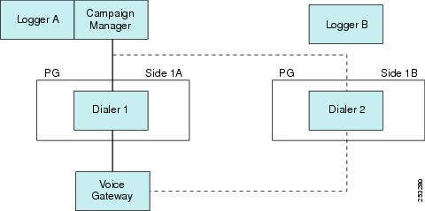
This figure shows the installation of redundant SIP Dialers with a single Gateway. The Dialers are shown to be installed on Side A and Side B of the redundant PGs. The port capacity depends on the type of Cisco Voice Gateway deployed. This deployment model is used when scaling and high availability are not factors.

Figure 5. Single Gateway Deployment for SIP Dialer

Note


This figure does not show the optional redundant Campaign Manager.


The SIP Dialer architecture supports only one active SIP Dialer per peripheral. Configure only one SIP Dialer. You install two Dialers on separate PG platforms, but you use the same Dialer Name.

For Unified CCE deployments, the SIP Dialer and Media Routing PG processes can run on a separate VM or on the same VM as the Agent PG. For a deployment with redundant SIP Dialers and MR PGs on the Agent PGs, each MR PG has one MR PIM that connects to the coresident SIP Dialer.

The SIP Dialer uses the local static route file to place and transfer outbound calls when Sip Server Type is set to Voice Gateway in the Dialer setup dialog. These outbound calls are transferred to CVP or outbound agents. Make sure that the SIP Dialer uses the local static route file for single gateway deployments.

The SIP Dialer uses the Unified SIP Proxy server to place and transfer outbound calls when Sip Server Type is set to CUSP Server in the Dialer setup dialog. These calls are placed or transferred to CVP or outbound agents.


Note


Codec configuration (G.729 versus G.711) impacts port capacity and CPU utilization of gateways. Configuring G.729 requires more DSP and CPU resources for gateways.


SIP Dialer with Multiple Gateways Deployment

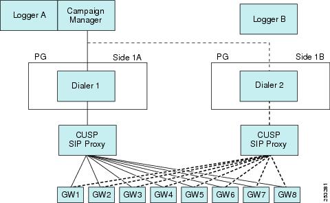
The following figure shows the deployment model for Unified SIP Proxy and eight Voice Gateways. The active Dialer points to the Unified SIP Proxy server. The proxy handles load balancing and failover. The SIP Dialer supports Unified SIP Proxy on the Cisco 3845 Integrated Services Router.

Figure 6. Multiple Gateway Deployment for SIP Dialer

Note


This figure does not show the optional redundant Campaign Manager.


In a multiple gateway deployment, the SIP Dialer requires Server Group and Route Table configurations on Unified SIP Proxy servers to identify the gateways. It also requires numbers so that the gateways can transfer customer calls to CVP or agents for the Dialer. Setting the Sip Server Type radio button to SIP Proxy in the Dialer setup dialog is required for multiple gateway deployment.

Outbound Option and Clustering Over the WAN

The deployment model for clustering Unified CCE over the WAN allows for improved high availability by deploying redundant components on the other end of the WAN. The "Single Campaign Manager, Importer, and Database" high-availability model differs from the model for clustering over the WAN. When deploying Outbound Option with clustering over the WAN, keep in mind that you only gain benefits with redundant Outbound Option components.

Distributed Deployments of Outbound Option

A distributed deployment model involves a central Unified CCE system and Unified Communications Manager cluster located at one site, with the Campaign Manager installed on the logger at this site, and a second site reachable over a WAN, which consists of the dialer, a PG, and a second cluster with Cisco Outbound Option.

For SIP Dialer deployment, a Unified SIP Proxy server is installed for one SIP Dialer on each PG side, and the Side A/Side B Dialer is targeting the same set of Voice Gateways through its own Unified SIP Proxy server. Multiple Voice Gateways can be installed locally to customer phones, or each Voice Gateway can be installed locally to an area so that tolls are not encountered if leased circuits or IP MPLS WAN circuits are available.

The Campaign Manager sends dialer records over the WAN, and the dialer places calls to local customers. The second site would support inbound agents as well.

The following bandwidth options are available between India and the US in customer environments:

  1. Terrestrial P2P leased 2 Mbps circuits

  2. Terrestrial P2P DS3 (44 Mbps) leased circuits

  3. IP MPLS WAN circuits. Varying speeds are available from the service provider depending on customer needs. Typical usage is 44 Mbps.

  4. The service provider hands off PRI (E1) trunks to India. The WAN cloud is usually built on SIP by the service provider. The service provider converts TDM to IP at the ingress/egress point in the United States and converts IP to TDM in India.

Options 1 and 2 above are the most common. Option 3 is becoming more popular with outsourcers because the MPLS cloud can connect to several of their customers. For example, the diagrams in the following sections show that the Outbound Contact Center System is deployed across multiple sites in the United States and India for various agent-based campaigns or transfer to a VRU campaign. The customers are in one country; for example, in the United States.

Distributed Deployment for Agent-Based Campaigns

This figure shows an example of a distributed deployment for an agent-based campaign.

Figure 7. Distributed Deployment Example for Agent-Based Campaign

In this distributed deployment example for an agent-based campaign:

  • The Voice Gateway and Router and Logger A servers are distributed between two sites (Site 1 and Site 3) in the United States.

  • The Unified Communications Manager cluster is located at Site 2 in India along with the Agent PG.

  • The redundant MRPG/Dialer and redundant Agent PGs are installed on the same VM at Site 2 in India.

  • The SIP Dialer at Site 2 uses the Voice Gateways that are located at Site 3 in the United States.

  • The Voice Gateways are included in the diagram with CT3 interface at Site 3 in the United States. These routers provide 1:1 redundancy for Dialer calls.

  • The Unified SIP Proxy servers are locally redundant at Site 2 to avoid the WAN SIP signaling traffic for transfering live outbound calls.

  • Each SIP Dialer connects to its own Unified SIP Proxy server at Site 2.

  • Each Unified SIP Proxy server controls the set of Voice Gateways at Site 3 in the United States.

  • Each Unified SIP Proxy server controls the set of Voice Gateways at Site 3 in the United States.

If recording is enabled at the SIP Dialer, the bandwidth requirements are as follows:

  • Answered outbound calls require the following bandwidth for each agent call:

    • G.711 Codec calls require a WAN bandwidth of 80 kbps

    • G.729 Codec calls require a WAN bandwidth of 26 kbps

  • Alerting outbound calls require the following bandwidth for each agent call:

    • G.711 Codec calls require a WAN bandwidth of 80 kbps

    • G.729 Codec calls require a WAN bandwidth of 26 kbps

Sizing for Outbound Option

Cisco Outbound Option can run fully blended campaigns in which agents can handle inbound and outbound calls alternately.


Note


See the chapter on configuration limits and feature availability for other limits that impact sizing.


When sizing your deployment, do not use the maximum outbound agents on a PG without also looking at expected hit rate, lines dialed per agent, and average handle times.

SIP Dialer targets the support of 1000 outbound agents for one PIM per PG. The number of supported agents is smaller when deploying mobile agents. To support this number of agents, the deployment must have at least five high-end gateways dedicated to outbound dialing.

SIP Dialer can support 3000 ports and 60 calls per second (CPS).

Each port can dial two calls per minute, assuming an average 30 seconds per call attempt, so 30 ports can handle one call per second for the Dialer. If the time to get all ports busy exceeds the average port busy time, then some ports are always idle.

Dialer Port Calculations

The following formula can be used to calculate the number of dialer ports that are required to achieve targeted call rate:

Number of Ports = [target call rate * average call duration * (1 + hit rate %)] 

This table shows the required ports to achieve targeted outbound call rates. These figures assume an average of 30 seconds per outbound call and a 20% hit rate.

Table 2. Ports Required to Achieve Targeted Outbound Call Rates

Targeted outbound calls per second

Number of ports required

10

360

20

720

30

1080

Voice Gateway Considerations

The most powerful Voice Gateway supports about 12 calls per second, even under the most favorable conditions. Five gateways can support an aggregate spike of up to 60 calls per second when evenly distributed. However, even distribution does not account for occasions when ports are tied up with agent or VRU calls after the transfer. So assuming a 50% transfer rate and using a conservative estimate, eight Voice Gateways are required to support a spike of up to 60 calls per second.

For the most current information about Voice Gateway models and releases that the SIP Dialer supports, see the Compatibility Matrix for your solution.

For gateway sizing considerations, see the published Cisco gateway performance data.

Agent PG Considerations

The Unified Communications Manager PIM can support up to 15 calls per second.

If the voice hit rate for the campaign is 15%, then the PG can sustain dialing at a rate of 100 calls per second.

Unified CM Considerations

The Unified CM subscriber supports a certain rate of outbound calls per second. To support a larger CPS at the Agent PG, distribute the Dialer across multiple subscribers using a Unified SIP Proxy server.

CUSP Considerations

A typical outbound call requires two transactions, if the call is transferred to an agent or VRU. A typical outbound call requires one transaction, if the call is not transferred to an agent or VRU.

CVP Considerations

Calls can be distributed to Unified CVP using translation routes. Any load balancing across Unified CVPs happens in the routing script.

Since four SIP Proxy transactions are required for some outbound call scenarios with Unified CVP, give Unified CVP its own Unified SIP Proxy server in large-scale deployments.

Mobile Agent Considerations

The SIP Dialer supports 500 unified mobile agents per Agent PG. With the SIP Dialer solution, the outbound calls have the same impact on Unified Communications Manager as inbound calls. Maintain a 2:1 ratio for number of inbound agents versus outbound agents. Since the SIP Dialer solution supports 1000 outbound regular agents per Agent PG, the SIP Dialer supports 500 outbound mobile agents per Agent PG.

SIP Dialer Throttling

In a single or multiple gateway deployment, the SIP Dialer raises an alarm if any gateway is overloaded. If you enable the autothrottle mechanism, the dialer also automatically throttles the dialing rate of overloaded gateways down to 10 percent of the configured port throttle value per 5000 customer attempts until 50 percent of the correction is met. 50 percent of the correction means that the SIP Dialer stops autothrottling when it reaches 50 percent of the configured port throttle value.


Note


The autothrottle mechanism is disabled by default. To automatically throttle overloaded gateways, enable the autothrottle mechanism by setting the value of registry key EnableThrottleDown to 1.

The SIP Dialer always raises an alarm when a gateway is overloaded, even when the autothrottle mechanism is disabled.


You can control SIP Dialer throttling with the field Port Throttle in the dialer configuration. Port Throttle indicates the number of ports to throttle per second. Setting the value to Port Throttle = 5 allows SIP Dialer to dial outbound calls at a rate of five calls per second per Dialer.

When the SIP Dialer connects to the Voice Gateway directly in the deployment, limit the dialer port throttle by the maximum dialer call setup rate listed on the gateway sizing table.

When the SIP Dialer connects through the CUSP in the deployment, the port throttle setting on the dialer must not exceed the total gateway capacity under assumption. Calls are load-balanced through CUSP and each gateway reaches its maximum available capacity. Limit the port throttle by the CUSP maximum transaction. Currently, the dialer maximum throttle setting is 60 calls per second. Under general transfer rate, calls through CUSP do not exceed maximum CUSP transaction rate given that CUSP is exclusively used by outbound deployments.

Set the port throttle value to 5 for Cisco 2800 Series Integrated Services Routers, set the port throttle value to 15 for Cisco 3800 Series Integrated Services Routers, and set this value to 20 for Cisco Access Servers and Universal Gateways.

Single Gateway Deployment

Use the following formula to calculate the Port Throttle if the gateway is dedicated 100% for outbound campaigns:

Port Throttle = (Value for Gateway)

Use the following formula to calculate the Port Throttle if the gateway is shared by multiple SIP Dialers for outbound campaigns:

Port Throttle = (Value for Gateway) / (Number of SIP Dialers)

Use the following formula to calculate the Port Throttle if the gateway is shared by multiple components (Unified CM, Unified CVP, and SIP Dialer) for inbound and outbound calls:

Port Throttle = (Value for Gateway) * (Percentage of outbound calls) * (1 – Hit Rate)
Multiple Gateway Deployment

Use the following formula to calculate the Port Throttle if the gateways are dedicated 100% for outbound campaigns:

Port Throttle = Total Values for Gateways

Use the following formula to calculate the Port Throttle if the gateways are shared by multiple SIP Dialers for outbound campaigns:

Port Throttle = (Total Values for Gateways) / (Number of SIP Dialers)

Use the following formula to calculate the Port Throttle, if the gateways are shared by multiple components (Unified CM, Unified CVP, and SIP Dialer) for inbound and outbound calls:

Port Throttle = (Total Values for Gateways) * (Percentage of outbound calls) * (1 – Hit Rate)

The throttling mechanism in the SIP Dialer process is not aware of which gateway the Unified SIP Proxy server selects to place outbound calls. Calculate the appropriate weight for each gateway in the Server Group configuration of the Unified SIP Proxy server for the load balance.

Weight = (Value for Gateway) / (Port Throttle) * 100

For example, assume a Cisco 3800 Series Gateway (192.168.10.3) and a Cisco 2800 Series Gateway (192.168.10.4) are used in a multiple gateway deployment. The following configuration allows that 3800 Series gateway in the cucm.example.com server group to receive 75 percent of the traffic and the 2800 Series gateway to receive 25 percent.

netmod(cusp-config)> server-group sip group cucm.example.com enterprise
netmod(cusp-config-sg)> element ip-address 192.168.10.3 5060 tls q-value 1.0 weight 75
netmod(cusp-config-sg)> element ip-address 192.168.10.4 5060 tls q-value 1.0 weight 25
netmod(cusp-config-sg)> lbtype weight
netmod(cusp-config-sg)> end server-group

SIP Dialer Recording

The SIP Dialer can record ("Recording") or enable the recording of Call Progress Analysis by third-party applications ("Media Termination") to be used for CPA troubleshooting. It does not record the full conversation.

There is usually no media stream between the SIP Dialer and the Voice Gateway. But when the recording or media termination is enabled in the Campaign configuration, the SIP Dialer requests the Voice Gateways to send the media stream to the SIP Dialer. The media stream is in G.711 or G.729 codec, depending on the dial peer configuration on the Voice Gateway. The SIP Dialer can record the media stream only with G.711 codec, but it can receive media streams for both G.711 and G.729 codecs to allow a third recording server to perform SPAN-based recording for outbound calls.

When "Recording" is enabled in the Campaign configuration, the SIP Dialer receives media streams, decodes RTP packets in G.711 codec, and writes them into a recording file. The SIP Dialer will send an alarm if the media stream is G.729 codec. The SIP Dialer has been tested to be able to support a maximum of 100 recording sessions per Dialer server due to CPU resource and disk I/O limitations.

When "Media Termination" is enabled in the Campaign configuration, the SIP Dialer will only receive the media stream to allow a third-party recording server to perform SPAN-based recording.

There is a limit for Media Termination Sessions because of a thread resource limitation per process. The SIP Dialer has to create a thread to listen on the media stream. The current limit for Media Termination Sessions is 200.

The SIP Dialer uses the following Registry keys to allow users to manage recording sessions and disk space:

Table 3. SIP Dialer Registry Keys

Name

Data Type

Description

Default Value

MaxRecordingSessions

DWORD

The maximum recording sessions per SIP Dialer, if the recording is enabled in the Campaign configuration.

100

MaxMediaTerminationSessions

DWORD

The maximum media termination sessions per SIP Dialer, if the recording is enabled in the Campaign configuration.

200

MaxAllRecordFiles

DWORD

The maximum recording file size (bytes) per SIP Dialer.

500,000,000

MaxPurgeRecordFiles

DWORD

The maximum recording file size (bytes) that SIP Dialer will delete when the total recording file size, MaxAllRecordFiles, is reached.

100,000,000

Outbound Option Bandwidth, Latency, and QoS Considerations

In many Outbound Option deployments, all components are centralized; therefore, there is no WAN network traffic to consider.

For some deployments, if the outbound call center is in one country (for example, India) and the customers are in another country (for example, US), then consider the WAN network structure under the following conditions:

  • In a distributed Outbound Option deployment, when the Voice Gateways are separated from the Outbound Option Dialer servers by a WAN.

  • When using Unified CVP deployments for transfer to a VRU campaign, and the Unified CVP servers are separated from the Outbound Option Dialer servers by a WAN. Provide Unified CVP with its own Cisco Unified SIP Proxy Server in the local cluster to reduce the WAN traffic.

  • When deploying a SIP Dialer solution for transfer to a VRU campaign, and the Cisco Unified SIP Proxy Servers for the SIP Dialers are separated from the Outbound Option Dialer servers by a WAN.

  • When the third-party Recording Server is separated from the Outbound Option Dialer servers by a WAN, configure the recording server local to the Voice Gateways.

Adequate bandwidth provisioning is an important component in the success of the Outbound Option deployments.

Impact of Redundant Campaign Manager, Outbound Option Importer, and Database

When using these redundant components, consider the following points:

  • Certain deployments can have increased WAN network traffic.

  • Messaging and record replication increases the bandwidth used between Side A and Side B.

Distributed SIP Dialer Deployment

SIP is a text-based protocol; therefore, the packets used are larger than some protocols. The typical SIP outbound call flow uses an average of 12,500 bytes per call that is transferred to an outbound agent. The average hit call signaling bandwidth usage is:

Hit Call Signaling Bandwidth = (12,500 bytes/call) (8 bits/byte) = 100,000 bits per call = 100 Kb per call

The typical SIP outbound call flow uses about 6,200 bytes per call that is disconnected by the outbound dialer. Those outbound calls can be the result of a busy ring no-answer, an invalid number, and so forth. The average non-hit call signaling bandwidth usage is:

Non-Hit Signaling Call Bandwidth = (6,200 bytes/call) (8 bits/byte) = 49,600 bits per call = 49.6 Kb per call

Codec Bandwidth = 80 Kbps per call for G.711 Codec,
or 26 Kbps per call for G.729 Codec

Agent-Based Campaign - No SIP Dialer Recording

This figure shows an example of the distributed Outbound SIP Dialer deployment for an agent-based campaign.

Figure 8. Distributed Outbound SIP Dialer Deployment for an Agent-Based Campaign

The average WAN bandwidth usage in this case is:

WAN Bandwidth = Calls Per Second * (Hit Rate * (Codec Bandwidth * Average Call Duration 
+ Hit Call Signaling Bandwidth) + (1 – Hit Rate) * Non-Hit Call Signaling Bandwidth) = Kbps
Example 1

With call throttling of 60 cps on the SIP Dialer, a 20% hit rate for the agent-based campaign, and a WAN link with G.711 codec and average call duration of 40 seconds, the bandwidth usage is:

60 * (20% * (80 * 40 + 100) + (1 – 20%)*49.6) = 41980.8 kbps = 41.98 Mbps
Example 2

With call throttling of 60 cps on the SIP Dialer, a 20% hit rate for the agent-based campaign, and a WAN link with G.729 codec and average call duration of 40 seconds, the bandwidth usage is:

60 * (20% * (26 * 40 + 100) + (1 – 20%)*49.6) = 16060.8 kbps = 16.06 Mbps
Agent-Based Campaign - SIP Dialer Recording

The average WAN bandwidth usage in this case is:

WAN Bandwidth = Calls Per Second * (Codec Bandwidth * Average Call Duration + Hit Rate 
* Hit Call Signaling Bandwidth + (1 - Hit Rate) * Non-Hit Call Signaling Bandwidth) = Kbps 
Example 3

With call throttling of 60 cps on the SIP Dialer, a 20% hit rate for the agent campaign, and a WAN link with average G.711 codec and average call duration of 40 seconds, the bandwidth usage is:

60 * (80 * 40 + 20% *100 + (1 – 20%)*49.6) = 199180.8 kbps = 199.18 Mbps
Example 4

With call throttling of 60 cps on the SIP Dialer, a 20% hit rate for the agent campaign, and a WAN link with average G.729 codec and average call duration of 40 seconds, the bandwidth usage is:

60 * (26 * 40 + 20% *100 + (1 – 20%)*49.6) = 67660.8 kbps = 67.66 Mbps
Transfer-To-VRU Campaign - No SIP Dialer Recording

The following figures show examples of the distributed Outbound SIP Dialer deployment for transfer to a VRU campaign.

Figure 9. Distributed Outbound SIP Dialer Deployment for Transfer to a VRU Campaign with CVP

The average WAN bandwidth usage in this case is:

WAN Bandwidth = Calls Per Second * Hit Rate * Hit Call Signaling Bandwidth + Calls Per Second 
* (1 - Hit Rate) * Non-Hit Call Signaling Bandwidth = Kbps
Example 5

With call throttling of 60 cps on the SIP Dialer, a 20% hit rate for the transfer-to-IVR campaign, and a WAN link with G.711 codec, the bandwidth usage is:

60 * 20% * 100 + 60 *(1 – 20%)*49.6= 3600 kbps = 3.6 Mbps
Transfer-To-VRU Campaign - SIP Dialer Recording

The average WAN bandwidth usage in this case is:

WAN Bandwidth = Calls Per Second * (Codec Bandwidth * Average Call Duration + Hit Rate 
* Hit Call Signaling Bandwidth + (1 - Hit Rate) * Non-Hit Call Signaling Bandwidth) = Kbps
Example 6

With call throttling of 60 cps on the SIP Dialer, a 20% hit rate for the agent campaign, and a WAN link with G.711 codec and average call duration of 40 seconds, the bandwidth usage is:

60 * (80 * 40 + 20% *100 + (1 – 20%)*49.6) = 199180.8 kbps = 199.18 Mbps 
Example 7

With call throttling of 60 cps on the SIP Dialer, a 20% hit rate for the transfer-to-VRU campaign, and a WAN link with G.729 codec and average call duration of 40 seconds, the bandwidth usage is:

60 * (26 * 40 + 20% *100 + (1 – 20%)*49.6) = 67660.8 kbps = 67.66 Mbps

Contact Center AI Services Considerations

Cisco Unified CCE solution leverages Artificial Intelligence (AI) and Natural Language Understanding (NLU) to provide the following Contact Center AI Services:

  • Virtual Agent–Voice (VAV) via cloud-based connector: Enables the customers to resolve issues within the IVR by integrating the IVR platform with cloud-based speech services.

  • Agent Answers: Assists the agents via Agent Answers gadget on the Cisco Finesse desktop by providing relevant suggestions and recommendations in real time.

  • Call Transcription: Assists the agents via Call Transcript gadget on the Cisco Finesse desktop.

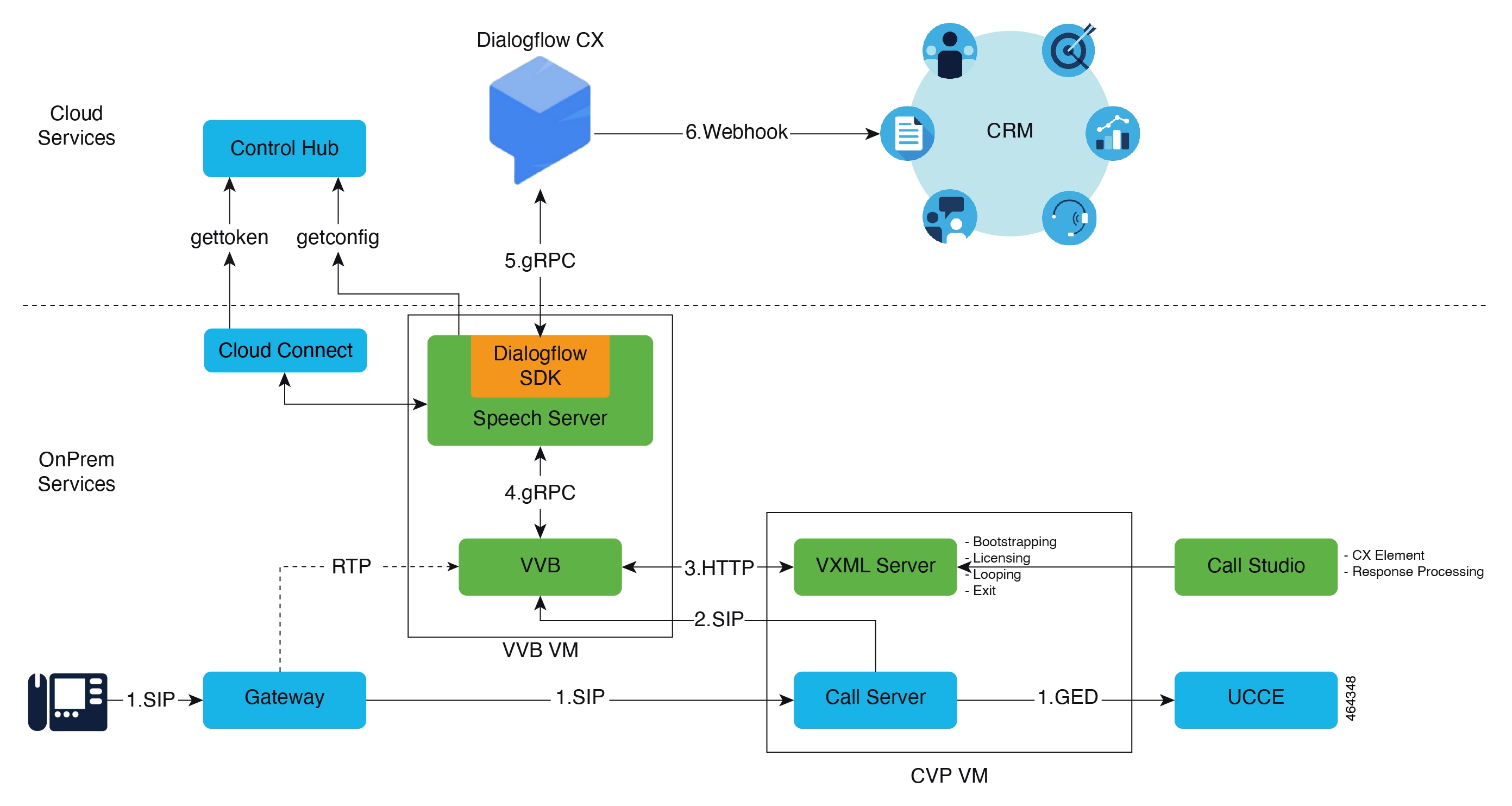
Figure 10. Contact Center AI Services Architecture

Unified CCE solution integrates with the following to provide the Contact Center AI Services:

  • An AI provider such as Google's CCAI is an extension of services that assist human agents in conversations with end users by providing real-time documents and response suggestions. For more details, see https://cloud.google.com/solutions/contact-center.

  • Webex Contact Center AI (Webex CCAI) services offer AI capabilities and mediation services between different AI service providers:

    • Webex CCAI Orchestrator service routes the voice streams of a conversation to the chosen AI Service provider (such as Google CCAI) in real time.

    • Webex CCAI API service receives the AI service provider's response from the Webex CCAI Orchestrator service. These responses are provided to the Agent Answers and Call Transcript gadgets.

  • Webex Cloud is a multi-tenant cloud solution which manages the tenant and its configuration.

  • Webex Common Identity (Webex CI) authenticates the tenant before allowing access to Webex CC/Webex CCAI services.

  • CUBE acts as a gateway in the call flow and forks the media streams of the agent and the caller towards the Webex CCAI Orchestrator service via the WebSocket protocol.

  • VVB interfaces with the Orchestrator Service for providing VAV capability. While the call is in the IVR state, VVB acts as a gateway to the Orchestration Service via the GRPC protocol.

In CCE, the customer associates the Contact Center AI Services with all or specific call types and then provisions these services for a specific agent or multiple agents. In Cisco Finesse, the customer configures the Agent Answers and Call Transcript gadgets for the required teams. During an incoming call, if the CCE and Agent Desktop configurations are present for an agent and if the call has associations to the AI services, the gadgets are displayed to the agents. When the agent speaks with the caller:

  • The Agent Answers gadget displays relevant suggestions and recommendations in real time for the agent to consider. The suggestions and recommendations are based on the ongoing conversation between the caller and the agent.

  • The Call Transcript gadget dynamically converts the ongoing conversation to text and presents the text to an agent for real-time viewing and reference.

Regionalized Media Support for Contact Center AI Services

Regionalized Media is now supported for Contact Center AI (CCAI) services, allowing you to localize media flow for specific regions. When using any of the CCAI services, the media flow can be customized according to your specific region. Adopting this regionalized media approach reduces latency, enhances audio quality, and allows for tailored regional configurations in multinational deployments while maintaining an unchanged user experience.

For more information on how to enable the regional media support, refer to the Agent Answers, Call Transcription and Virtual Agent - Voice chapters of the Cisco Unified Contact Center Enterprise Features Guide.

Prior to enabling Regionalized Media support for CCAI, the premise components were configured to connect to the default CCAI cloud services data centers associated with your organization. For example, if your organization was set up in the United States (US) data center, you would have accessed CCAI cloud services located in the US, irrespective of the physical location of your contact center.

After enabling regionalized media support for CCAI (by installing CVP ES15 and VVB ES5), the premise components use a designated variable to connect to the nearest CCAI cloud services data center. These components use this variable to establish the service URL for CCAI cloud services. For example, if your organization has a tenant in the United States but needs to access CCAI cloud services from a remote location, such as India, you can configure the on-site components to connect to the nearest CCAI cloud services data center (India), which is identified by the variable specific to India.

Design Considerations

To adopt regional media and optimize the media flow path, CCAI services would be routed to the nearest Cisco regional media data center. To leverage regional media, you must enable the designated variable when provisioning SIP headers in an outbound SIP invite message sent from the Session Border Controller (SBC) or Cisco Unified Communications Manager (CUCM) to CVP.

Bandwidth and Latency Considerations

For the bandwidth and latency considerations specific to the regional media, refer to the existing bandwidth and latency guidelines for Agent Answers or Virtual Agent (depending on the service being used) in the Bandwidth, Latency, and QoS Considerations section.

Serviceability Considerations

The existing serviceability guidelines apply to regional media as well. For more information, refer to the Serviceability Guide for Cisco Unified ICM/Contact Center Enterprise.

Contact Center AI Services Call Flow

Figure 11. Contact Center AI ServicesCall Flow Diagram

Note


Unified CCE solution components fetch and cache the CCAI authentication token from Cloud Connect to establish communication with the Webex CCAI Orchestrator service. The dotted lines in the preceding image indicate that the authentication tokens are fetched only once from Cloud Connect and not for every call.


  1. An incoming call arrives at CUBE.

  2. CUBE directs the call to CVP.

  3. CVP requests for call treatment instruction from CCE. CCE instructs CVP to subject the call to the standard VAV/IVR treatment.

  4. VVB fetches the Auth token from Cloud Connect, calls the InsightInfer API over GRPC, and sends the media to the Webex CCAI Orchestrator.

  5. Webex CCAI connects with Google CCAI, calls the Analyzecontent API, and relays the media.

  6. Google CCAI sends back the response to be played back to the caller.

    1. VVB processes the response and plays the prompt to the caller further to collect the inputs.

    2. The conversation goes on with voice and DTMF with the caller and CCAI service.

  7. CCE instructs CVP to queue the call until an agent becomes available. When an agent is available, CCE sends the GED CONNECT message to the CVP. The GED CONNECT message indicates which Contact Center AI Services are enabled for that agent. CVP transfers the call to the agent through Unified CM.

  8. CCE sends the call information (which includes details on which Contact Center AI Services are enabled for that call) to the Finesse server.

  9. The call arrives at the Agent Desktop from Finesse. If the Contact Center AI Services are configured for the agent and if the Agent Answers and Call Transcript gadgets are configured on the Agent Desktop, the gadgets are displayed to the agent in the Agent Desktop.

  10. If the GED CONNECT message (received at step 7) indicated that at least one Contact Center AI Service is enabled for the agent, CVP requests CUBE to start forking the media streams of the agent and the caller. The forking request informs CUBE about which AI services are enabled for that call and where the forked media streams should be sent to.

  11. When CUBE receives the forking request, it attempts to establish a WebSocket connection with the Webex CCAI WebSocket server. When the WebSocket connection is successful, CUBE starts forking the media streams of the agent and the caller towards Webex CCAI.

  12. The Webex CCAI Orchestrator Service passes the media streams of the agent and the caller to Google CCAI (or other AI services). Google CCAI processes the media streams and generates the transcripts and suggestions as response.

  13. The Webex CCAI Orchestrator Service publishes the responses received from Google CCAI to the Webex CCAI API Service.

  14. The Agent Answers and Call Transcript gadgets request for Contact Center AI Services by invoking the Webex CCAI API Service.

  15. The Agent Answers and Call Transcript gadgets start displaying the response received from the Webex CCAI API Service to the agent in real-time. If the call has gone through the IVR/VAV phase, the call transcript of that conversation is also displayed in the gadget.

For details on how to configure Contact Center AI Services, see the Virtual Agent–Voice, Agent Answers, and the Call Transcription for Agent/IVR/Virtual Agent-Voice chapters in the Cisco Unified Contact Center Enterprise Features Guide at Cisco Packaged Contact Center Enterprise Features Guide at https://www.cisco.com/c/en/us/support/customer-collaboration/packaged-contact-center-enterprise/products-maintenance-guides-list.html.

Courtesy Callback Considerations

Courtesy Callback reduces the time callers have to wait on hold or in a queue. Your solution can call back callers who meet your criteria, instead of having them wait on the phone for an agent. The caller who has been queued by Unified CVP can end the call. The solution then calls them back when an agent is close to becoming available (preemptive callback).

Preemptive callback does not change the time that a caller waits for an agent. It enables the caller to end the call and not remain in queue listening to music. Callers who remain in queue and those who opt for the callback treatment appear the same to agents answering the call.


Note


Scheduling a callback to occur at a specified time is not part of this feature.


Figure 12. Courtesy Callback Components. This figure shows the components used for the Courtesy Callback feature.


Note


Do not allow the caller to invoke the Courtesy Callback applications more than once for the same call on the VXML Server.

Courtesy Callback uses the TCL service on IOS Voice Gateway and a built-in feature on Cisco VVB.


Courtesy Callback Use Case

In your callback script, you can establish criteria for offering a caller courtesy callback. These are examples of callback criteria that you can establish:

  • Expected wait for a customer in queue exceeds some maximum number of minutes, based on your average call handling time per customer.


    Note


    The included sample scripts use this method for determining callback eligibility.


  • Assigned status of a customer. You can offer gold customers the opportunity to be called back, instead of remaining on the line.

  • The particular service that a customer requests. You can establish sales calls or system upgrades as callback criteria.

Courtesy Callback Call Flows

If the caller opts for a callback, they leave their name and phone number. Their request remains in the system. The system places a callback to the caller when the Estimated Wait Time (EWT) reaches the correct value. The caller answers the call and confirms that they are the original caller, and the system connects the caller to the agent after a short wait.


Note


Courtesy Callback is also supported for IP-originated calls.


A typical call flow for this feature follows this pattern:

  1. The call arrives at Unified CVP and the call is treated in the VRU environment.

  2. The Call Studio and Unified CCE Courtesy Callback scripts determine if the caller is eligible for a callback based on your rules.

  3. If the caller is eligible, the system announces the EWT and offers the caller a callback when an agent is available.

  4. The caller chooses what to do:

    1. If the caller chooses not to use the callback feature, queuing continues.

    2. If the caller chooses to receive a callback, the system prompts the caller to record their name and to key in their phone number.

  5. The system writes a database record to log the callback information.


    Note


    If the database is not accessible, the system does not offer a callback to the caller.


  6. The caller disconnects from the TDM side of the call. However, the IP side of the call in Unified CVP and Unified CCE is still active. This keeps the call in the same queue position. No queue music plays, so Voice Browser resources used during this time are less than for a caller actually in the queue.

  7. When an appropriate agent is close to being available (as determined by your callback scripts), then the system calls the person back. The system announces the recorded name when the callback is made to ensure that correct person accepts the call.

  8. A VRU session asks the caller to confirm that they are the correct person and that they are ready for the callback.

    If the system cannot reach the callback number (for example, busy lines, RNA, or network problems), then the call is not sent to an agent. The call also does not go to the agent if the caller does not confirm that they are the correct person. The agent is guaranteed that someone is waiting when they take the call. The system assumes that the caller is already on the line by the time the agent gets the call.

    This feature is called preemptive callback because the system assumes that the caller waits a minimal time for the agent and the caller is on the line when the agent answers.

  9. The system presents the call context on the agent screen-pop.

If the system cannot reach the caller after a configurable number and frequency of retries, the callback cancels and the database status updates appropriately. You can run reports to determine if any manual callbacks are necessary based on your business rules.

See the Configuration Guide for Cisco Unified Customer Voice Portal at https://www.cisco.com/en/US/products/sw/custcosw/ps1006/products_installation_and_configuration_guides_list.html for a call flow description of the scripts providing the Courtesy Callback feature.

Courtesy Callback Design Impacts

Consider the following design impacts for Courtesy Callback feature:

  • The callback uses the same Ingress Gateway through which the call arrived. The outbound calls cannot be made on any other Egress Gateway.

  • Queue calls that allow callback on a Unified CVP VXML Server.

  • Courtesy Callback requires the Unified CVP Reporting Server.

  • Answering machine detection is not available for this feature. During the callback, the caller is prompted with a brief VRU session message and acknowledge with DTMF that they are ready to take the call.

  • Calls that are transferred to agents using DTMF *8, TBCT, or hookflash cannot use Courtesy Callback.

  • Courtesy Callback doesn't support Agent call transfers to the CCB Queue, over a computer telephony integration (CTI) route point.

  • Callbacks are a best-effort function. After a limited number of attempts to reach a caller during a callback, the callback is terminated and marked as failed.

  • Configure the allowed or blocked numbers that Courtesy Callback uses to place calls through the Unified CVP Operations Console .

  • The media inactivity detection feature on the Voice Browser can affect waiting callback calls. For more information, see the Configuration Guide for Cisco Unified Customer Voice Portal.

  • Courtesy Callback call flow routed via CUCM is not supported, even though they originate at CUBE.

  • Courtesy Callback requires an accurate EWT calculation for its optimal behavior.

    Do the following to optimize the EWT, when using Precision Queues for Courtesy Callback:

    • Queue the calls to a single Precision Queue

    • Do not include a Consider If expression when you configure a step.

    • Do not include a wait time between steps or use only one step in the Precision Queue.


      Note


      Use simple Precision Queue definitions (for example, with one step and one-to-one agent mapping). The complexity of Precision Queues makes calculating accurate EWT difficult.


  • Courtesy Callback supports 900 calls with 10 CPS. One reporting server can be configured to support 900 CCB calls simultaneously with standard reporting enabled.


Note


CCB does not support the use of SRTP.


Callback Time Calculations

The following sections provide an overview of how callback time is determined.

These are some definitions of key terms used:

  • Wait Time—The interval of time between when the call enters the queue and when the call leaves the queue.

  • Reconnect Time—The interval between when the callback starts and when the caller accepts the callback and is waiting for an agent.

  • Callback in Queue Time—The interval between when the caller reconnects and when the call leaves the queue.

  • Service Level Agreement (SLA)—Average of Callback in Queue Time. Average means that roughly 50 percent of calls are within the service level and 50 percent are outside the service level.

  • Average Dequeue Time—The average number of seconds that it takes for a call to leave the queue.

  • Remaining Time—The number of seconds left to count down to call back the caller.

Callback in Queue Time

The average Callback in Queue Time after a callback is based on an agreed service level. Courtesy Callback also avoids calling back too early or too late, as both scenarios are undesirable. If callers are called back too early, they are more likely to have to wait in the queue for a longer time. If the callback is made too late, there is a greater chance that your agents could be idle and waiting for calls.

The remaining time changes when the dynamics of a call center change. Such changes include when more or fewer agents are available or when the average handle time changes. Courtesy Callback calculates the Average Dequeue Time based on various factors, such as calls in queue, average handle time, and agents in ready and talking states.

The Average Dequeue Time updates when a call enters the queue and when it leaves the queue. Calculations use this information to reduce the Callback in Queue Time and minimize times when your agents wait for calls.

Process Details and Calculation Methods

Courtesy Callback uses the following formula to determine the Average Dequeue Time and to update the remaining time for all Courtesy Callback calls in the queue.


Note


Courtesy Callback can support a default wait time of 30 minutes with a maximum exception of 90 minutes.


Average Dequeue Time Calculation

The Average Dequeue Time (D) is calculated using the formula:

D = (EWT + F)/N

Where:

  • EWT is the estimated wait time for a new Courtesy Callback call.

  • F is the number of seconds that the first call is already in position in the queue.

  • N is the number of calls in queue.


Note


The Dequeue Time plays a significant role in the optimal behavior of the Courtesy Callback feature. The average Dequeue Time is calculated based on factors such as call volume, agent availability, and the average handle time for a particular skill group.

The Estimated Wait Time (EWT) is an approximation. The uniformity of average handling time and agent availability for a particular skill group drive its accuracy. If these factors are not uniform, it leads to a difference between the announced wait time and the actual callback time. The use of microapps can insert calls into the queue that were not included in the EWT calculation. For scripting of calls that include Courtesy Callback, queue all calls on the VRU using VxmlScripting, instead of microapps.


Remaining Time Calculation

The remaining time for a callback in the queue is calculated using this formula:

R(p) = p*D - F - C

Where:

  • p is the current queue position of the call from 1 to N.

  • R(p) is the remaining time for the Pth queue position Courtesy Callback call.

  • C, the post-callback time, is the sum of the time to get the Courtesy Callback caller back on the phone and the SLA time.


Note


  • With time in first place (RPT.ewtWithFirstInQueueTime in reporting.properties) = true,

    The remaining time is calculated as:
    R(p) = p*(EWT + F)/ N - F - C
  • With time in first place (RPT.ewtWithFirstInQueueTime in reporting.properties) = false (default),

    The remaining time is calculated as:
    R(p) = p*(EWT)/ N - F - C

Example Scripts and Audio Files

This feature uses Unified CCE scripts. Modifiable example scripts are provided on the Unified CVP install media in \CVP\Downloads and Samples\. These scripts determine whether to offer a callback to the caller. The files provided are:

  • CourtesyCallback.ICMS, the Unified CCE script

  • CourtesyCallbackStudioScripts.zip, a collection of Call Studio scripts

Sample audio files for these scripts are installed to <CVP_HOME>\OPSConsoleServer\CCBDownloads\CCBAudioFiles.zip and also as part of the Media Files installation option.

If you use CCBAudioFiles.zip, unzip the contents onto the media server. CCBAudioFiles.zip has Courtesy Callback-specific application media files under en-us\app and media files for Say It Smart under en-us\sys. If you already have media files for Say It Smart on your media server, then you only require the media files under en-us\app.


Note


The default prompts work for most of the default Call Studio scripts. Review and provision the Say It Smart plugin prompts for specific cases that the default prompts do not cover.


The sample scripts use the default location of http://<server>:<port>/en-us/app. Change the default location of the sample audio files in the sample scripts for your environment. (That is, substitute the media server IP address and port in <server> and <port>).

The following example scripts are provided:

  • BillingQueue—This script plays queue music to callers that either choose not to have a callback or who reenter the queue after receiving a callback. You may customize this script to suit your business needs.

  • CallbackEngine—This script keeps the VoIP leg of a callback alive between when a caller opts for a callback and when a caller receives the callback.


    Important


    Do not customize this script.


  • Callback Entry—This script handles the initial VRU when a caller enters the system and provides the caller the opportunity to receive a callback. You may customize this script to suit your business needs.

  • CallbackQueue—This script handles the keepalive function of a call while a caller is in queue and listening to the music.


    Important


    Do not customize this script.


  • CallbackWait—This script handles the VRU portion of a call when a customer is called back. You may customize this script to suit your business needs.


Note


The Courtesy Callback sample files and scripts are also available on DevNet (Customer Voice Portal (CVP) > Downloads > Courtesy Callback Sample Scripts) at https://developer.cisco.com/site/customer-voice-portal/.


Database Lookup Design Considerations

  • Application Gateway has more overhead in setting up an integration with the GED 145 interface but offers more flexibility in how data is accessed.

  • CVP APIs offer REST API or database or custom integration options which also offload processing on the primary routing engine in the solution. The downside is that CVP processing across multiple nodes adds to complexity in coordination and maintenance. It also does not have all of the context available while running in routing script.

  • Database Lookup has a lower cost of setup than application gateway and makes the information available within the script were reporting objects are accessible, but there are some limitations on how data is indexed, and what data will be available. Database Lookup also provides a way to access external data brought into the script without utilizing ECC variables as are commonly used in Application Gateway or CVP integrations to push data to the router.

Database Lookup Call Flows

The basic Database Lookup call flow runs as shown in this diagram.

Figure 13. Database Lookup Call Flows

Database Lookup Sizing Considerations

The supported Database Lookup rate aligns with the maximum call rate for the system.

Database Lookup Design Impacts

  • The external database is required to be hosted on a virtual machine that is separate from the virtual machines the Packaged CCE solution is hosted on.

  • The external database must be running a compatible version of the Microsoft SQL Server.

  • The timeouts configured for Database Lookup should be consistent and align with other request timeouts. If utilized in a Contact Director route to a target instance, the Database Lookup should be 25% of the route request timeout.

  • The Database Lookup node is based on a single primary key. Complex queries are not supported.

  • The total size of the data from all the columns must not exceed 3500 bytes.

Digital channels integration using Webex Connect considerations

Cisco Contact Center Enterprise (CCE) integrates with Webex Connect to create a seamless omnichannel experience for your agents. This integration helps your customers to interact across voice and digital communication channels.

Digital channels integration architecture overview

The following diagram depicts the high-level deployment architecture of the digital channels integration with CCE:

Figure 14. Digital Channels Integration with Webex Connect—Architecture
  1. The Webex Connect platform brings in the ability to receive customer inquiries from a range of digital messaging channels (SMS, Live Chat, and Email) and facilitates automated handling of these inquiries by leveraging AI-powered bots. To offer these digital channel capabilities to the Cisco Contact Center Enterprise (CCE) customers, you must integrate Webex Connect with CCE. In the Webex Connect platform, configure channel assets and nodes that you can use for creating routing flows for the various incoming tasks across digital channels. For more information, see Webex Connect and Cisco Contact Center Enterprise System (CCE).

  2. When there is a manual intervention required, that is when a task needs to be escalated to a live agent on CCE, Webex Connect populates the Expanded Call Context (ECC) variable, user_DR_ MediaResourceID, with the conversation ID. For more information about ECC variables, see the ECC variables for Digital Routing tasks section in the Scripting and Media Routing Guide for Cisco Unified ICM/Contact Center Enterprise.

  3. Webex Connect then injects the new task request into the Digital Routing service that runs as a container on the Cisco Cloud Connect platform. The task request is routed through a pair of reverse proxy servers that run in a Demilitarized Zone (DMZ) network, which is front ended with a load balancer. The load balancer provides a URL using which the incoming tasks are injected into the Digital Routing service. The reverse proxy servers are two distinct entities that do not communicate with each other, however, they have an in-built mechanism to identify the active side of the Digital Routing service to inject the task. For more information about how to configure reverse proxy servers, see the Reverse Proxy Configuration for Digital Channel Interaction section in the Cisco Packaged Contact Center Enterprise Features Guide.

  4. The Digital Routing service sends the task request to the Unified ICM router through the Media Routing Peripheral Gateway.

  5. Unified ICM runs the routing script that takes the longest available agent (LAA) in the precision queue or skill group for the script. Unified ICM then sends two messages—one message to the Agent Peripheral Gateway about the agent assigned to the task and another message to the Digital Routing service through the MR-PG notifying the selected agent details.

  6. The Digital Routing service sends the agent details as an asynchronous webhook notification to Webex Connect.

  7. Webex Connect calls the Webex Engage API to add the agent to the conversation. You must synchronize the agent details between Webex Engage and Contact Center Enterprise using the DataConn service that runs as a container on the Cloud Connect platform. For more information about agent synchronization, see Synchronise CCE agents to Webex Engage.

  8. The agent receives a notification pop-up in the Manage Digital Channels gadget. When the agent accepts the task request, the conversation that includes bot interactions is presented to the agent. For more information about how to configure the Manage Digital Channels gadget, see the Manage Digital Channels gadget section in the Cisco Finesse Administration Guide.

  9. The task requests such as transfer and close that originate from Cisco Finesse are directly invoked on the Digital Routing service using the mandatory Expanded Call Context (ECC) variables, user_DR_Primary and user_DR_Backup. For more information about the ECC variables, see the ECC variables for Digital Routing tasks section in the Scripting and Media Routing Guide for Cisco Unified ICM/Contact Center Enterprise.

  10. The Digital Routing service sends the transfer and close requests as Webhook notifications to Webex Connect.

Synchronise CCE agents to Webex Engage

For CCE agents to be able to take up the digital channel tasks initiated from Webex Connect, the agent configuration details must be synchronized between the AW database and Webex Engage. The DataConn service that is running on the publisher node of Cloud Connect platform is responsible for synchronizing agent configurations. For the synchronization operations to complete, the bulk agent synchronization callback request is invoked on the publisher node. This callback request is originated from the Webex Engage cloud node and is routed through load balancer, reverse proxy and cloud. The following diagram depicts how the agent configurations are synchronized:

  1. The DataConn service reads the agent configurations available in the AW database and sends a user configuration API request to Webex Engage.

  2. The Webex Engage sends an asynchronous response request to the DataConn service through the load balancer, which is the network entry point for your deployment. For instructions about how to configure the host for network entry points, see the Configure network entry point for agent synchronization section in the Cisco Packaged Contact Center Enterprise Features Guide.

  3. The DataConn service maps the agent configuration details from the AW database with the configurations available in Webex Engage to synchronize the details. For details about the mapping, see the Field mapping between Webex Engage and CCE section in the Cisco Packaged Contact Center Enterprise Features Guide.

  4. Only agents configured for digital channels are synchronized to Webex Engage. For instructions about how to enable agents for digital channels, see the Enable agents for Digital Channels section in the Cisco Packaged Contact Center Enterprise Features Guide.

Rate Limits for Digital Routing Requests

Webex Connect injects Digital Routing task requests into CCE through Task API and Cisco Finesse sends transfer or close task requests to CCE through TaskAction API. These rate limits are implemented at the edge reverse proxy (if you are using the Nginx reverse proxy provided by Cisco) as well as Cisco Web proxy service running on the Cloud Connect node that caters to Web requests/HTTPS requests. When the rate limits are applied, a HTTP status code of 429 (too many requests) is returned. When you see this status code, you can choose to provide an appropriate handling of the contact in your flow. For example, you can invoke a web callback request to have an agent call back the customer after the issue is resolved.

The following tables list the rate limits that the Digital Routing service enforces at the Reverse Proxy and Cloud Connect Web Proxy services:

Table 4. Rate Limits at Reverse Proxy Service

API

Request Type

URI

Limit on Requests

Limit on Connections

DR Tasks

POST/GET

/drapi/v1/tasks*

100 requests per second

  • HTTP1 –50

  • HTTP2 –250

USER SYNC CALLBACK

POST

/dataconn/synccallback

5 requests per minute

  • HTTP1 –50

  • HTTP2 –250

Table 5. Rate Limits at Cloud Connect Web Proxy Service

API

Request Type

URI

Limit on Requests

Limit on Connections

Tasks

POST

/drapi/v1/tasks

50 requests per second

100

Tasks

GET (single task)

/drapi/v1/tasks/0f1f7a57-8908-4ca9-8260-d0283bfb5fa3

50 requests per second

100

TaskAction

POST

/drapi/v1/tasks/0f1f7a57-8908-4ca9-8260-d0283bfb5fa3/taskAction

50 requests per second

100

Digital Routing API task flows

Data Flow for New Task Request

The following diagram illustrates how the data flows across components when a new task request is injected:

Figure 15. New Task Request
  1. When a Digital Channel contact is received over one of the channels that are supported by Webex Connect, a flow is invoked in Connect that would create a new conversation in Webex Engage. The conversations begin with self-service and bot interactions, and if necessary, get escalated to a live agent by invoking a Digital Routing request to CCE. An Engage ConversationID is generated to track the conversation in Engage, which is used as the conversation store to track all messages received from the customer.

  2. Webex Connect initiates a CCE Create Task API request towards the Digital Routing service through a load balancer or reverse proxy server. The Webex Connect Flow transaction ID ($flid) is converted into a universally unique identifier (UUID) and passed into the payload as client TaskID. The request also contains the script selector that would be sent to CCE along with any additional task context in the form of call variables and Expanded Call Context (ECC) variables. The Webex Engage ConversationID is also passed along as a special ECC variable called user_DR_MediaResourceID. This ECC variable is essential for the Agent Desktop to be able to load the conversation.

  3. The Digital Routing service acknowledges the API request with a response code "201 / Created".

  4. The Digital Routing service sends a webhook notification to indicate that the task with specified TaskID is created and is waiting to be sent to CCE for routing.

  5. The Digital Routing service replicates the task request to its peer to provide redundancy.

  6. The Digital Routing service forwards the request to MR PIM along with all the task context and maintains a unique DialogueID for the task until an agent gets assigned from CCE. It additionally includes the FQDN of the Cloud Connect pair in special ECC variables user_DR_Primary and user_DR_Backup.

  7. When the task gets submitted to MR PIM for queuing and routing, a QUEUED Webhook event is sent to Webex Connect, which will trigger the corresponding QUEUED Webex Connect flow that can be used to relay information to the end customer.

  8. The MR PIM forwards the request to the CCE router. The client TaskID received from the Digital Routing service is passed as UsertoUserInfo (UUI) field in the request and the same is stored in the Route_Call_Detail and Termination_Call_Detail tables to track a Digital Routing request in CCE.

  9. The CCE router invokes the scheduled script, based on the script selector received in the request to find a suitable agent.

  10. The CCE router sends a message to the Agent PG to reserve the agent allocated for the task and to also provide context for the impending task that is being routed to the agent. Simultaneously, it informs the MR PIM about the agent who is allocated to the task including any updated task context that should be relayed back to Webex Connect.

  11. The Agent PG informs the Finesse server about the incoming task for the agent. On the MR PG side, the MR PIM sends a message to the Digital Routing service containing the Agent ID (AgentSkillTargetID) of the agent who has been assigned to the task.

  12. The Digital Routing service invokes the ROUTED webhook event that invokes the corresponding Webex Connect flow. On the Agent Desktop a "New Dialog Notification" is received, which allows the agent to accept the task, and add it to the Task pane.

  13. The Webex Connect ROUTED flow adds the specified agent to the existing "Conversation" in Webex Engage using the ConversationID relayed in the webhook event as part of the special ECC variable user_DR_MediaResourceID.

Data Flow for Transfer Task Request

The following diagram illustrates how the data flows across components when a transfer task is initiated:

Figure 16. Transfer Task Request
  1. A transfer request in the form of TaskAction API with the Operation field set to routed-transfer is initiated from Cisco Finesse on the primary Digital Routing service from where the task was injected into the CCE system.

  2. The Digital Routing service acknowledges the receipt of the request.

  3. Finesse sends a message to the CTI server to indicate the end of the current task.

  4. The CTI server sends a message to Finesse to indicate that the task is closed successfully in CCE.

  5. The Digital Routing service communicates with Webex Connect through the TRANSFERRED webhook event, and starts a timer of 15 seconds for the Webex Connect to reinject the task back into CCE. The webhook notification indicates the script selector received from Finesse agent, so that the same can be employed by Webex Connect to reinject the task back into CCE.

  6. The Webex Connect flow for the Transferred event processing calls the 'Remove Participant' node / API to remove the transferring agent from the conversation based on the ConversationID and ParticipantID. The ParticipantID is the task's OwnerID that contains the Agent SkillTargetID value from CCE.

  7. After the agent is removed from the conversation, the 'Transferred' event flow creates a new task request to the Digital Routing service. The new task request has the same TaskID as the original request, but has a new script selector and task context that is received in the TRANSFERRED webhook notification. After receiving the new task API request, the Digital Routing service cancels the timer and moves the task back to Created state. If the new task is not received before the timer is up, the service moves the task to the Closed state with the disposition code, CD_TASK_TRANSFER_TIMEOUT.

  8. The Digital Routing service acknowledges the API request with a response code, "200 / OK".

  9. The Digital Routing service sends a webhook notification to indicate that the task with specified TaskID is created and is waiting to be sent to CCE for routing.

  10. The Digital Routing service initiates a new task request on the MR PIM. The new task request has:

    • The PreviousTaskId field set to the ICMTaskID of the task being transferred.

    • The ServiceRequested field set to ROUTE_SERVICE_REQUEST_TRANSFER.

  11. The Digital Routing service sends a webhook notification to indicate that the task with specified TaskID is queued for processing.

  12. CCE allocates an agent and informs MR PG. The MR PIM sends a message to the Digital Routing service with the details of the new agent who is assigned to the task.

  13. The Digital Routing service initiates a ROUTED webhook notification to indicate that the task with specified TaskID is transferred to a new agent. The Webex Connect ROUTED flow adds the specified agent to the existing "Conversation" in Webex Engage using the ConversationID relayed in the webhook event as part of the special ECC variable, user_DR_MediaResourceID.

Data Flow for Close Task Request

The following diagram illustrates the scenario when a task is closed either by the agent or the customer after the task is routed to the Finesse desktop and the agent has started working on the task:

Figure 17. Close Task Request
  1. The Cisco Finesse server sends a taskAction REST API request to the Digital Routing service that had injected the task into CCE. This is determined by the ECC variable, user_DR_Primary or user_DR_Backup that is received from the Agent PG. The Finesse server indicates a disposition code CD_NORMAL_END_TASK to convey that this is a task completion that the agent has initiated. If the Digital Routing service call times out or receives an error, the Cloud Connect node that is identified using the user_DR_Backup variable is attempted. If the customer leaves the chat in the middle of the conversation, the agent is notified about the same and the agent can move to the Wrap-up state. When the agent clicks the Complete or Close button in the Manage Digital Channels gadget, Finesse sends the taskAction API for the close operation.

  2. The Digital Routing service acknowledges the API request with a response code, "200 / OK".

  3. The Digital Routing service sends a webhook notification to indicate that the task with specified TaskID is closed with a disposition code. Use the disposition code to determine if the task was closed generally or whether it was force-closed due to some error. If the customer conversation is still open in Webex Connect or Webex Engage, the customer is informed about the reason for task closure through the same media channel.

  4. Finesse sends a message to the CTI server for the specified ICMTaskID. The request has the ICM Disposition set to CD_NORMAL_END_TASK(38), which results in a Termination_Call_Detail record in the CCE database for the task.

  5. The CTI server responds with an acknowledgement message to Finesse.

  6. On the Webex Connect side, the flow that was run because of the Closed Webhook event invokes the 'Close Conversation' node to end the conversation in Webex Engage. The ConversationID is extracted from the user_DR_MediaResourceID ECC variable in the Webhook event. A flow designer relays a message to the customer stating that the conversation has been closed, based on the channel the conversation was on.

Abandoned Task Data Flow

When a customer abandons a task after the task request is initiated into the Digital Routing service and before the agent starts working on the task, the following scenarios are considered:

Data Flow for Abandoned Task on Agent Desktop

The following diagram illustrates the flow when a customer abandons the task after it is routed to an agent on the Agent Desktop:

Figure 18. Abandoned Task on Agent Desktop
  1. When a Digital Channel contact is received over one of the channels that are supported by Webex Connect, a flow is invoked in Connect that would create a new conversation in Webex Engage. The conversations begin with self-service and bot interactions, and if necessary, get escalated to a live agent by invoking a Digital Routing request to CCE. An Engage ConversationID is generated to track the conversation in Engage, which is used as the conversation store to track all messages received from the customer.

  2. Webex Connect initiates a CCE Create Task API request towards the Digital Routing service through a load balancer or reverse proxy server. The Webex Connect Flow transaction ID ($flid) is converted into a universally unique identifier (UUID) and passed into the payload as client TaskID. The request also contains the script selector that would be sent to CCE along with any additional task context in the form of call variables and Expanded Call Context (ECC) variables. The Webex Engage ConversationID is also passed along as a special ECC variable called user_DR_MediaResourceID. This ECC variable is essential for the Agent Desktop to be able to load the conversation.

  3. The Digital Routing service acknowledges the API request with a response code "201 / Created".

  4. The Digital Routing service sends a webhook notification to indicate that the task with specified TaskID is created and is waiting to be sent to CCE for routing.

  5. The Digital Routing service replicates the task request to its peer to provide redundancy.

  6. The Digital Routing service forwards the request to MR PIM along with all the task context and maintains a unique DialogueID for the task until an agent gets assigned from CCE. It additionally includes the FQDN of the Cloud Connect pair in special ECC variables user_DR_Primary and user_DR_Backup.

  7. When the task gets submitted to MR PIM for queuing and routing, a QUEUED webhook event is sent to Webex Connect, which will trigger the corresponding QUEUED Webex Connect flow that can be used to relay information to the end customer.

  8. The MR PIM forwards the request to the CCE router. The client TaskID received from the Digital Routing service is passed as UsertoUserInfo (UUI) field in the request and the same is stored in the Route_Call_Detail and Termination_Call_Detail tables to track a Digital Routing request in CCE.

  9. The CCE router invokes the scheduled script, based on the script selector received in the request to find a suitable agent.

  10. The CCE router sends a message to the Agent PG to reserve the agent allocated for the task and to also provide context for the impending task that is being routed to the agent. Simultaneously, it informs the MR PIM about the agent who is allocated to the task including any updated task context that should be relayed back to Webex Connect.

  11. The Agent PG informs the Finesse server about the incoming task for the agent. On the MR PG side, the MR PIM sends a message to the Digital Routing service containing the Agent ID (AgentSkillTargetID) of the agent who has been assigned to the task.

  12. The Digital Routing service invokes the ROUTED webhook event that invokes the corresponding Webex Connect flow. On the Agent Desktop a "New Dialog Notification" is received, which allows the agent to accept the task, and add it to the Task pane.

  13. The Webex Connect ROUTED flow adds the specified agent to the existing "Conversation" in Webex Engage using the ConversationID relayed in the webhook event as part of the special ECC variable user_DR_MediaResourceID.

  14. For asynchronous digital channels such as SMS, the Webex Connect flow detects the customer's intent (based on specific keywords) to quit the chat due to no response from the agent. For Live Chat, the customer closes the Live Chat window on the browser when there is no response from the agent. The Webex Connect flow uses an Evaluate node to detect whether the task is currently assigned to an agent or not by checking whether the conversation status and userID. The Webex Connect flow includes an End Task node that calls the Close taskAction API on the Digital Routing service with one of the following disposition codes:

    • CD_NORMAL_END_TASK—If the Conversation Status is "Active" and the "userId" is not null.

    • CD_TASK_CUSTOMER_ABANDON—All other cases when Conversation Status is not "Active".

  15. The Digital Routing service returns a response code "200 / OK" to acknowledge and accept the request.

  16. The Digital Routing service sends a Webhook notification to Webex Connect with the disposition code CD_NORMAL_END_TASK for the Closed event.

  17. The Closed flow in Webex Connect initiates the Close Conversation node to clear the conversation in Webex Engage.

  18. If the agent clicks the closed task in the Task pane that is available in the Agent Desktop, the Manage Digital Channels gadget attempts to load the conversation and may fail because the conversation is already closed in Webex Engage.

  19. The Finesse server initiates the message towards Agent PG to clear the task in CCE with the ICM Disposition set to CD_TASK_ABANDONED_WHILE_OFFERED(37).

  20. The Agent PG responds back to the Finesse server with a message confirming that the task is cleared in CCE.

  21. The Finesse server initiates the taskAction Close API to clear the Digital Routing service memory.

  22. If the task is already in Closed state in the Digital Routing service memory, Finesse clears the task from it's memory as well.

Data Flow for Abandoned Task at CCE Router Queue

The following diagram illustrates the flow where Webex Connect initiates the CCE End Task node to abandon the task after the Digital Routing service has initiated the NEW_TASK request to MR PIM, and before the CCE router has found an agent for the task:

Figure 19. Abandoned Task at CCE Router Queue
  1. Webex Connect initiates a CCE Create Task API request to the Digital Routing service through a load balancer or reverse proxy server. The Webex Connect Flow transaction ID ($flid) is converted into a universally unique identifier (UUID) and passed into the payload as client TaskID. The request also contains the script selector that would be sent to CCE along with any additional task context in the form of call variables and Expanded Call Context (ECC) variables. The Webex Engage ConversationID is also passed along as a special ECC variable called user_DR_MediaResourceID. This ECC variable is essential for the Agent Desktop to be able to load the conversation.

  2. The Digital Routing service acknowledges the API request with a response code "201 / Created".

  3. The Digital Routing service sends a webhook notification to indicate that the task with specified TaskID is created and is waiting to be sent to CCE for routing.

  4. The Digital Routing service sends a routing request to MR PIM. The task includes the script selector and task context variables.

  5. The MR PIM forwards the request to the CCE router to queue the task.

  6. The Digital Routing service initiates the Webex Connect Webhook URL to indicate that the task is submitted to CCE router for queuing.

  7. Customer abandons the task at this stage. Webex Connect flow invokes the End Task node, which internally invokes the Close TaskAction API with the disposition code set to CD_TASK_CUSTOMER_ABANDON.

  8. The Digital Routing service acknowledges the request with a response code "200 / OK".

  9. Since a route request for the task is already sent to the MR PIM / CCE Router, the Digital Routing service sends the request to MR PIM to cancel the queueing of the task at the CCE router.

  10. The MR PIM notifies the router to abandon the queued task.

  11. The router cancels the queueing and responds back with a message back to MR PIM.

  12. The MR PIM sends an acknowledgement message to the Digital Routing service.

  13. The Digital Routing service initiates a CLOSED webhook event to Webex Connect to indicate that the task is closed successfully.

  14. The Webex Connect flow that corresponds to the CLOSED webhook event initiates the Close Conversation node to clear the conversation in Webex Engage.

Data Flow for Abandoned Task at Digital Routing Service Queue

The following diagram illustrates the scenario when the customer abandoned a task, which is queued in the Digital Routing service:

Figure 20. Abandoned Task at Digital Routing Service Queue
  1. When the customer closes the chat session for Live Chat tasks or when Webex Connect receives the close or stop task request over asynchronous channels like short message service (SMS) in the Webex Connect flow, Webex Connect initiates the CCE End Task node, which in turn initiates the Close TaskAction API request that has the Operation field set to Close and the disposition code as CD_TASK_CUSTOMER_ABANDON.

  2. The task is still in the Digital Routing service queue and is not sent to the MR PIM. The Digital Routing service removes the task from its internal queue.

  3. The Digital Routing service acknowledges the Close TaskAction API request with a response code, "200 / OK".

  4. The Digital Routing service sends a webhook notification to indicate that the task with specified TaskID is closed with the disposition code CD_TASK_CUSTOMER_ABANDON.

  5. The Webex Connect flow for Closed Webhook event invokes the Close Conversation API of Webex Engage to clear the conversation.

Mixed Codec Considerations

Contact center enterprise solutions support G.711 codec only for VRU. The SIP carrier or TDM-IP gateway sends the capability as G.711 and G.729, with a higher priority for G.729. The prompts at the Voice Browser should be G.711. The agents support both G.711 and G.729, with a higher priority for G.729. This configuration avoids the use of transcoders for VRU and connecting calls to agents. You can avoid the use of universal transcoders for Whisper Announcement by defining dual codecs for the ingress gateway and Unified CM.

VRU is negotiated as G.711. The solution automatically renegotiates the caller-agent conversation as G.729 to save bandwidth over WAN links.

You can use either G.711 mu-law or a-law prompts, but configure the entire solution for the same format.

G.711 a-law supports the following features:

  • Agent Greeting

  • Whisper Announcement

  • Unified CM-Based Silent Monitoring

  • Outbound SIP Dialer

  • Courtesy Callback

  • Post Call Survey

  • Mobile Agents


Note


SIP Dialers with CUBE can support a-law with specific design considerations. The SIP Dialer does not advertise a-law. The solution needs DSP resources (transcoder) on CUBE during the initial negotiation (no media) between the SIP Dialer and the SIP service provider. During a REFER from the Dialer to the agent, CUBE renegotiates the code with the agent to use a-law. CUBE then releases the DSP resource (transcoder).


Mixed Codec Use Case

Use mixed codecs to avoid transcoders and DSP resources. Define a dual codec at the ingress and egress gateways and Unified CM. The VRU automatically negotiates the call as G.711. The system then renegotiates the call as G.729 or G.711 for the caller-agent conversation.

Mixed Codec Call Flows

Logical Flow During VRU

  1. A call arrives at the ingress voice gateway (G.729, G.711). The gateway sends a SIP invite message to the SIP Proxy Server, which forwards the request to the Unified CVP SIP Service.

  2. CVP sends the call to the Voice Browser.

  3. The call is established with G.711 codec without the use of transcoders.

Logical Flow During Caller and Agent Conversation

  1. A call arrives at the ingress voice gateway (G.729, G.711). The gateway sends a SIP invite message to the SIP Proxy Server, which forwards the request to the Unified CVP SIP Service.

  2. CVP sends the call to Unified CM to route to a Unified CCE agent.

  3. The call is renegotiated and established as G.729 without the use of transcoders.

Mixed Codec Design Impacts

Design impacts for mixed codec are:

  • A SIP trunk that only supports G.729 forces the use of transcoders.

  • Certain features, such as Whisper Announcement, require universal transcoders for G.729 to G.729 interworking.

  • If transcoders are required due to single G.729 codec, use Unified CM controlled transcoding resources. They trigger automatically for any codec mismatch.

  • Sizing of appropriate transcoding and universal transcoding resources are required based on call flows, supplementary services, and certain integrated features.

Mobile Agent Considerations

Unified Mobile Agent enables an agent with any PSTN phone and a broadband VPN connection to function like a local agent in a formal contact center.

Unified Mobile Agent uses a pair of CTI ports that function as proxies for the mobile agent phone (or endpoint) and the caller phone (or endpoint). Every signed-in mobile agent requires two CTI ports, that's local and remote. The CTI ports take the place of the Cisco IP Phone that Unified CM JTAPI controls. The agent signs in to the local CTI port DN and Unified CM routes calls for the mobile agent to that DN. In a nailed connection, the remote CTI port calls the agent during sign-in. However, in a call-by-call connection, the Unified CM routes a call to the agent. By using media redirection, the CTI ports signal for the two VoIP endpoints to stream RTP packets directly. There's no further involvement from the CTI ports until further call control (transfer, conference, hold, retrieve, or release) is required. The agent performs any subsequent call control from the agent desktop. The PG transmits the necessary subsequent call control by JTAPI to Unified CM for the CTI ports to control the media of the call.

Figure 21. Cisco Unified Mobile Agent Architecture

The two CTI ports (local and remote) are logically and statically linked within the PG software. The PG registers the CTI ports at PG initialization. Call observers are added for these two CTI Ports when a mobile agent signs in. The PG provides call control for the CTI Ports and the call. The voice path is between the two voice gateways.

At the contact center, a mobile agent can sign in as a local agent from a JTAPI-controlled phone, using the same agent ID. Historical call reporting doesn't distinguish between calls handled as a mobile agent or a local agent.


Note


  • Unified Mobile Agent can't use IPv6-enabled CTI ports.

  • To record transferred calls in queue, from Unified Mobile Agent to Unified CVP, we recommend that you record the calls using the remote CTI port instead of the local CTI port.


Connection Modes

With Unified Mobile Agent, you can configure agents to use either call-by-call dialing, a nailed connection, or allow agents to make the choice during sign-in.

With call-by-call connections, consider these points:

  • If the agent phone is configured for voicemail, then disable voicemail to let the RONA call processing to occur.

  • An agent must answer the phone by going off the hook and end the call by disconnecting their phone. The Answer button on the agent desktop is disabled.

  • An agent can't end one leg of a transfer without ending it at the other leg. The transfer must be completed or both legs must be dropped.

  • Autoanswer isn’t possible. There’s no call control mechanism to make the mobile agent phone go off the hook.

With nailed connections, consider these points:

  • A mobile agent can log off by using the desktop or by just disconnecting the phone.

  • You can use autoanswer in a nailed connection.

  • The following Unified CM timers can end a mobile agent call:

    • Maximum Call Duration timer (the default value is 720 minutes)

    • Maximum Call Hold timer (the default value is 360 minutes)

    To keep the mobile agent signed in, set the values for both of these timers to 0 so these timers never expire.

  • Your firewall can block the media stream if:

    • An agent is idle for longer than the firewall idle timeout value.

    • The firewall idle timeout expires.

    To prevent this issue, increase the firewall idle timeout value.

Mobile Agent Call Flows

Call-By-Call Connection Call Flow

In call-by-call dialing, the agent’s remote phone is dialed for each incoming call. When the call ends, the agent’s phone is disconnected before the agent is made ready for the next call.

A basic call flow for this type of dialing is as follows:

  1. At sign-in, a mobile agent specifies their agent ID, password, a local CTI port DN as the extension, and a phone number at which to call them. The administrator preselects the CTI port DN based on the agent's location.

  2. The queueing process works the same for a mobile agent as for a local agent.

  3. When a mobile agent is selected for the call, the new processing for a mobile agent begins. The Router uses the directory number for the agent’s local CTI port as the routing label.

  4. The incoming call rings at the agent's local CTI port. The Agent PG is notified that the local CTI port is ringing but does not answer the call immediately. The caller now hears ringing.

  5. Simultaneously, a call to the agent is initiated from the remote CTI port for the selected agent. This process can take a while to complete, depending on the connection time. If the agent does not answer within the configured time, RONA processing starts.

  6. When the agent answers their phone by going off-hook, this second call is temporarily placed on hold. Then, the original customer call is answered and directed to the agent call media address. The agent call is then taken off hold and directed to the customer call media address. The result is an RTP stream directly between the two VoIP endpoints.

  7. When the call ends, both connections disconnect and the agent is set to ready, not ready, or wrap-up, as appropriate.

Nailed Connection Call Flow

In nailed connection mode, the agent is called once at sign-in, and the line stays connected through multiple customer calls.

A basic call flow for this type of connection is as follows:

  1. At sign-in, a mobile agent specifies their agent ID, password, a local CTI port DN as the extension, and a phone number at which to call them. The administrator preselects the CTI port DN based on the agent's location. A remote CTI port is statically associated with the local CTI port.

  2. The remote CTI port starts a call to the phone number that the mobile agent supplied. When the agent answers, the call is immediately placed on hold. The agent is not signed in and ready until this process completes.

  3. The queueing process works the same for a mobile agent as for a local agent.

  4. When a mobile agent is selected for the call, the new processing for a mobile agent begins.

  5. The incoming call rings at the local CTI port for the mobile agent. The JTAPI gateway detects that the CTI port is ringing, but does not immediately answer the call. The caller now hears ringing.

  6. The agent's desktop indicates that a call is ringing. The agent phone does not ring because it is already off hook. If the agent does not answer within the configured time, RONA processing begins.

  7. When the agent presses the Answer button to accept the call, the customer call is answered and directed to the agent call media address. The agent call is then taken off hold and directed to the customer call media address.

  8. When the call ends, the customer connection disconnects and the agent connection is placed back on hold. The agent is set to ready, not ready, or wrap-up, depending on agent configuration and agent desktop input.

Outbound Call Flow for Mobile Agent

Mobile agents can participate in outbound campaigns only on a nailed connection.

The call flow for predictive, progressive, or preview dialing is as follows:

  1. The mobile agent signs in using the local CTI port DN as the agent phone number.

  2. The standard Outbound Option call flow occurs.

  3. When the Router selects the mobile agent, the MR PG returns the label (local CTI port DN) for an available agent to the dialer.

  4. The dialer places a reservation phone call to the local CTI port DN and automatically places it on hold.

  5. In progressive or predictive mode, when the dialer selects the mobile agent to handle a live call, the dialer transfers the call to the local CTI port.

    In preview mode, when the dialer reaches a live call on behalf of the mobile agent, the dialer transfers the call to the local CTI port.

  6. The dialer auto-answers the transferred call for the agent through the CTI server. This quickly establishes the voice path between the customer and the agent. The dialer then disconnects the reservation call to the mobile agent.

Mobile Agent Design Impacts

Unified Mobile Agents can sign in to Unified CCE with any PSTN phone that gets routed to a Cisco Voice Gateway. Mobile agents also require an agent desktop.

You can use any Voice Gateway that Unified CCE supports for mobile agents. You can register the Voice Gateway with the same Unified CM cluster as the Agent PG or with another cluster. The caller (ingress) and mobile agent (egress) Voice Gateways can use either MGCP or SIP.


Note


If you enable Silent Monitoring, use different Voice Gateways for ingress and egress.


Unified Mobile Agents can use a Cisco IP Phone that is configured for SIP. Calls to mobile agents can also originate from SIP IP Phones.

For improved Unified CM performance, use Extension Mobility, instead of Unified Mobile Agent, for mobile agents with IP Phones on the same cluster as the Agent PG. Because the IP Phone device is associated with the JTAPI user, there is a small performance hit on Unified CM for making that association.

Consider the following factors when designing a Unified Mobile Agent solution:

Agent Location and Call Admission Control Design

Because a CTI port is a virtual type of endpoint, it can be located anywhere. But, always configure the CTI ports for a mobile agent with the same location as the agent’s VoIP endpoint. The CTI port pair for a mobile agent must also be colocated with the Voice Gateway (or VoIP endpoint) that calls the agent. If you do not have both these conditions, call admission is not accounted for correctly.

Call admission control sees the mobile agent call as two separate calls. The first call leg is from the caller to the agent’s local CTI port. The second call leg is from the remote CTI port to the agent. Because the CTI ports are colocated with the agent endpoint, call admission control counts only the call from the caller location to the agent location. This is why it is important for an agent to use CTI ports for their current location.

From the perspective of call admission control locations for the mobile agent CTI ports, there are three deployment scenarios:

  • Use CTI ports colocated with the egress Voice Gateway that calls the mobile agent.

  • Use CTI ports colocated with the ingress Voice Gateway.

  • Use CTI ports colocated with the intercluster trunk between Unified CM clusters.

All pools of CTI ports are colocated with the VoIP endpoint type for the agent (Voice Gateway or IP phone).

Callers and agents can also use VoIP endpoints on another Unified CM cluster. This configuration enables agents in remote locations to be called from local Voice Gateways for a different Unified CM cluster.


Note


If you use Silent Monitoring in this case, your solution requires a monitoring server at the remote site with the agent (egress) Voice Gateway.


For additional information about call admission control design, see the call admission control information in the Cisco Collaboration System Solution Reference Network Designs at http://www.cisco.com/go/ucsrnd.

Dial Plans for Mobile Agent

Configure the Unified CM Dial Plan so that it routes calls from the remote CTI port to a Voice Gateway colocated with the mobile agent CTI ports. Otherwise, call admission control accounting does not work correctly.

You can also configure the Unified CM Dial Plan so that all calls from the CTI ports go through a specific gateway regardless of the called number. In that configuration, you have a dedicated gateway that all mobile agents use. It is more easily managed, but it might not be an efficient configuration from the perspective of PSTN trunk usage.

For additional information about dial plan design, see the Cisco Collaboration System Solution Reference Network Designs.

Codec Design for Mobile Agent

Media streams between the ingress and egress Voice Gateways can be G.711 or G.729. You cannot mix codecs, because all CTI ports for a PG must advertise the same codec type. This requirement can result in G.711 (instead of G.729) calls being sent across the WAN. If you route most calls to agents colocated with the ingress Voice Gateway, sending a few G.711 calls over the WAN might not be an issue. The alternative is to use G.729 for all mobile agent calls. If most Unified CCE calls cross a WAN segment, it probably makes sense to have all CTI ports configured for G.729. However, you cannot have G.711 for some mobile agent calls and G.729 for others. Your solution requires a dedicated region for the CTI ports to ensure that all calls to and from this region use the same encoding format.

For additional information about codec design considerations, see the Cisco Collaboration System Solution Reference Network Designs.

Music on Hold with Mobile Agent

You can use Music on Hold (MoH) for mobile agents just as you do for traditional agents. To let callers hear music, assign MoH resources to the Ingress Voice Gateway. Specify the user or network audio source on the local CTI port configuration. To let the agent hear music when on hold, assign MoH resources to the Egress Voice Gateway. Specify the user or network audio source on the remote CTI port configuration.


Note


Always assign the MoH resources to the gateways. Do not assign MoH resources to local and remote CTI ports. It is unnecessary and can have a performance impact on the system.


A Mobile Agent remote call over a nailed connection is put on hold when there is no active call to the agent. In general, enable MoH to the mobile agent phone for nailed connection calls. If MoH resources are an issue, consider multicast MoH services.

For a nailed connection, disabling MoH for the remote phone might lead to the hold tone playing instead. This depends on the call processing agent that controls the remote phone. For Unified CM, the hold tone is enabled by default and is similar to the Mobile Agent connect tone. With the Unified CM hold tone enabled, it is difficult for the agent to identify if a call has arrived by listening for the Mobile Agent connect tone. Therefore, disable the hold tone for Unified CM by changing the setting of the Tone on Hold Timer service parameter on Unified CM.

For additional information about MoH design, see the Cisco Collaboration System Solution Reference Network Designs.

Cisco Finesse with Mobile Agent

Cisco Finesse supports mobile agents. The Cisco Finesse server needs no configuration to enable the Mobile Agent feature. To use the Mobile Agent feature, follow all configurations as outlined in Cisco Unified Contact Center Enterprise Features Guide.


Note


Cisco Finesse IP Phone Agent does not support mobile agents.


On the Cisco Finesse sign-in page, if you select the mobile agent check box, the mobile agent options are presented to the agent. The mobile agent provides the local CTI port extension, a mode (Call by Call or Nailed Connection), and a dial number for the agent’s phone.

The agent's phone number must route to a VoIP endpoint (Voice Gateway, IP phone, or intercluster trunk) colocated with the CTI port pair for call admission control to work properly.

A Cisco Finesse mobile supervisor can perform all of the functions that a nonmobile supervisor can perform, except for Silent Monitoring. Cisco Finesse does not support Silent Monitoring of mobile agents.

DTMF Considerations with Mobile Agent

If mobile agents consult a VRU or other network component that uses DTMF to navigate, your solution might require MTP resources. The Mobile Agent feature relies on CTI ports, which do not support in-band DTMF (RFC 2833). If the agent's endpoints support only in-band DTMF (or if they are configured for in-band DTMF per RFC 2833), then Unified CM automatically inserts MTP resources to handle the mismatch. Ensure that sufficient MTP resources are available in this case.

Session Border Controllers with Mobile Agent

Some SIP devices, such as the Cisco Unified Border Element or other Session Border Controllers, can dynamically change the media port during a call. If this happens with a Mobile Agent call, your solution requires MTP resources on the SIP trunk that connects to the agent endpoint.

Fault Tolerance for Mobile Agent

The RTP stream for a mobile agent call is between the Ingress and Egress Voice Gateways. Because of this, a failure of Unified CM or Unified CCE does not affect call survivability. However, after a failover, subsequent call control (transfer, conference, or hold) might not be possible. The mobile agent's desktop notifies them of the failover and the agent must sign in again.

Sizing Considerations for Mobile Agent

Mobile agent call processing uses more server resources. This reduces the maximum supported agents on both the Unified CM subscriber and the Agent PG as follows:

  • 2000 with nailed-up connections (1:1)

  • 1500 with nailed-up connections if the average handle time is less than 3 minutes, or if agent greeting or whisper announcement features are used with the mobile agent (1.3:1)

  • 1500 with call-by-call connections (1.3:1)


    Note


    The Large PG OVA supports 2000 agents with call-by-call connections.


Unified Mobile Agent uses conference bridge resources for Agent Greeting. With Agent Greeting, size each call as if it had a conference, rather than the greeting.

Unified Mobile Agent requires the use of two CTI ports per contact center call. One CTI port controls the caller endpoint, and the other CTI port controls the selected agent endpoint. The actual RTP stream is between the two endpoints and its bridged through these two CTI ports. However, there is extra call processing on Unified CM to set up calls to mobile agents through these two CTI ports.

Mobile agents can essentially sign in from any location (with the agent desktop) where they have a high-quality broadband connection and a PSTN phone. However, they are still associated logically with a particular Agent PG and Unified CM cluster, even if the Voice Gateway is registered with a different cluster. The agent is associated with a particular peripheral and cannot migrate freely to other peripherals without some custom modifications.

For specific subscriber and cluster sizing, use the Cisco Unified Communications Manager Capacity Tool. When sizing the cluster, input the maximum number of simultaneously signed-in mobile agents. To handle the configured mobile agents above your maximum simultaneous signed-in mobile agents, enter Type 1 CTI ports with a BHCA and BHT of 0 in the tool. This is similar to the method for accounting for local agent phones that are not signed in by using the CTI third-party controlled lines in the tool. As an alternative, you can input all mobile agents (signed-in and not signed-in) into the tool and adjust the BHCA and BHT per mobile agent accordingly. The total BHCA and BHT must remain the same as when considering simultaneous signed-in mobile agents with their actual BHCA and BHT.

Phone Extension Support Considerations

Consider these aspects for using phone extensions in your solution.

Your contact center can handle the following types of calls, each with its own considerations:

  • Routed ACD Calls – Calls routed to an agent through a central queue that is based on skill or attribute.

  • Routed Agent Calls – Calls routed to a particular agent where the customer has a specific business relationship with this agent.

  • Non-routed calls – Direct dialed calls, possibly through a Direct Inward Dial extension or from unmonitored phones within the business.

  • Agent to Agent calls – Calls placed between agents, either routed or not routed.

A phone extension can be either:

  • ACD Extension – The extension the agent logs into, to which calls are routed.

  • Secondary extension – Sometimes called a non-ACD extension. This is generally an extension where calls are not routed. The agent can use it for business or personal activity. The solution might monitor activity on this extension, depending on configuration, which impacts available features.

Monitored Secondary Extensions

Multi-Line Agent Control (MLAC) is a Cisco CCE agent peripheral setting which enables reporting and call control for calls on the secondary extensions. Use of MLAC imposes some restrictions, such as:

  • No call waiting

  • A limit to four extensions for each agent phone

  • No shared lines between agents

  • Applies to all phones on a given peripheral when enabled

Unmonitored Secondary Extensions

The solution does not track call activity on an unmonitored secondary extension. A secondary extension can have PBX functions that are not generally associated with contact center actions, like the use of shared lines.

Call Type Considerations for Phone Extensions

Non-Routed Direct Agent Dialing

If an ACD line receives calls that are not routed, or that are routed regardless of state, it can impact agent experience and reporting. A direct call from another agent can arrive while an agent is on a call or in a wrap-up state.

If your business model allows, the call flows are cleaner if all calls are routed to agents, even agent-to-agent calls. Write the routing script to take the agent state into account. Otherwise, there are possible race conditions that can impact reporting and agent experience.

Direct Agent Dialing

When agents have relationships with their customers and provide a direct number, there are a few options on how to deploy.

If you use the agent’s primary extension for these direct dialed calls, then consider these options:

  • Non-Routed — The calls go directly to the agent’s ACD extension bypassing routing. Always enable call waiting on the phone. A VRU of routing script cannot add call context. But, if the calling number is not blocked, you can customize Finesse to perform an external database dip if the agent is signed in.

  • Routed — If you route the calls to the agent’s ACD extension, you get richer reporting, can include more call context, and can make routing decisions based on agent state:

    • You can queue the call until the agent is available using a Queue to Agent node.

    • You can send the call to a signed-in agent regardless of state using an Agent to Agent node.

    • You can send the call to an agent’s extension or to voicemail using a Label node.

    • You can use the requery option on those nodes if the agent doesn’t answer or invokes a busy condition.

Shared ACD Line Support

Contact Center Enterprise Solutions include shared ACD line support for up to five devices, enabled via agent desk settings configuration. This support enables an agent with devices at different locations to utilize the same extension. The agent selects which device to make active via the device selection screen. That device remains associated with the agent for the duration of their login session, and can change only after they log out and log back in to the system. The active device is the device used when the agent answers a call or makes a call from the device selection screen. Note, however, that all devices ring when a call is sent to that extension.


Note


Although an agent uses only one device at a time, the agent PG actively monitors for calls on any of the shared devices on that line. For example, if you have 2000 concurrent agents, each with two active devices, the PG is actively monitoring 4000 devices. During graceful shutdown, agents and calls move from the active side to the idle side PG so maintenance can be performed on that VM. If a PG is monitoring more than 5000 devices during graceful shutdown, delays may cause issues. If this situation could occur in your deployment, use the Large OVA PG for best results.


Note


UCM auto-answer is not supported when shared ACD lines are in use. Agent Desk Settings auto-answer is supported.

.


E.164 Dial Plan Design

Unified CCE supports E.164 dial plans and provides partial support for the ‘+’ prefix as follows:

  • Agent extensions cannot include the ‘+’ character.

  • Agent secondary lines cannot include the ‘+’ character if the agent peripheral has “All Lines” Agent Control enabled.

  • The VRU cannot include the '+' prefix unless you route DNs through a CTI Route Point.

  • Dialer-imported contact numbers and campaign prefixes cannot include the ‘+’ prefix.

  • Agents can dial the ‘+’ prefix with an E.164 number through their Cisco Finesse desktop.

  • Agents can dial the ‘+’ prefix with an E.164 number through their phones.

For contact centers that advertise the agent extension outside of the contact center, these considerations apply:

  • Use transformation patterns to add the ‘+’ prefix to the calling number on outgoing calls. You can use Calling Party Transformation CSS for phone configuration.

  • To route incoming calls addressed to an E.164 number with the ‘+’ prefix, use called party transformations on the translation patterns to strip the ‘+’ prefix from the called number.

  • The Attendant Console does not have visibility into the phone status.

Post Call Survey Considerations

A contact center typically uses a post call survey to gauge customer satisfaction with their experience. For example, did the customer receive the necessary information using the self-service or did they have a pleasant experience with the agent.

The Post Call Survey (PCS) feature enables a call flow that transfers the caller to a DNIS that prompts the caller with a post call survey.

The VRU treatment asks the caller if they want to participate in a post call survey. There are two responses a caller can have to a post call survey request:

  1. If the caller chooses to do so, the call flow automatically transfers the caller to the survey call after the agent ends the conversation.

  2. If the caller declines, your Unified CCE script uses an ECC variable to turn off the Post Call Survey on a per-call basis. By setting the ECC variable to n, the call does not transfer to the PCS DNIS.

For reporting purposes, the post call survey call has the same Call-ID and call context as the original inbound call.

Post Call Survey Use Case

The caller is typically asked if they want to participate in a survey after the call. Your solution can determine based on dialed numbers to invoke the post call survey at the end of a call. When the customer completes the conversation with an agent, the customer is automatically redirected to a survey. When the agent ends the call, it initiates the Post Call Survey.

A customer can use the keypad on a touch tone phone and voice with ASR/TTS to respond to questions asked during the survey. For the solution, the post call survey call is just like another regular call. The Post Call Survey retrieves the call context information from the original customer call.

Post Call Survey Design Impacts

Observe the following conditions when designing a Post Call Survey:

  • A Post Call Survey initiates when the last agent ends the call. The call routing script launches a survey script.

  • The mapping of a dialed number pattern to a Post Call Survey number enables the Post Call Survey feature for the call.

  • The value of the expanded call variable user.microapp.isPostCallSurvey controls whether the call transfers to the Post Call Survey number.

    • If user.microapp.isPostCallSurvey is set to y (the implied default), the call transfers to the mapped post call survey number.

    • If user.microapp.isPostCallSurvey is set to n, the call ends.

    • To route all calls in the dialed number pattern to the survey, your script does not have to set the user.microapp.isPostCallSurvey variable. The variable is set to y by default.

  • You cannot have a REFER call flow with Post Call Survey. REFER call flows remove Unified CVP from the call. But, Post Call Survey needs Unified CVP because the agent has already disconnected.

  • For Unified CCE reporting purposes, the Post Call Survey call inherits the call context for the initial call. When a survey starts, the call context of the customer call that was transferred to the agent replicates into the call context of the Post Call Survey call.

  • The expanded call variable isPostCallSurvey will be cached only when the UCCE router generates a label for CVP.

Precision Routing Considerations

Precision routing offers a multidimensional alternative to skill group routing. Precision queues are the key components of precision routing. Using Unified CCE scripting, you can dynamically map the precision queues to direct a call to the agent who best matches the caller's precise needs. Precision queues consist of one or more steps with configured expressions allowing a customer to find the precise needs of the caller.

There is no need to add an agent to a precision queue; agents become members of precision queues automatically based on their attributes. Consider a precision queue that requires an agent in Boston, who speaks fluent Spanish, and who is proficient in troubleshooting a specific piece of equipment. An agent with the attributes Boston = True, Spanish = True, and Repair = 10 is automatically part of that precision queue. A Spanish-speaking caller in Boston who needs help with that equipment is routed to that agent.

Precision routing enhances and can replace traditional routing. Traditional routing looks at all of the skill groups to which an agent belongs and defines the hierarchy of skills to map business needs. However, traditional routing is restricted by its single-dimensional nature.

Precision routing provides multidimensional routing with simple configuration, scripting, and reporting. Agents have multiple attributes with proficiencies so that the capabilities of each agent are accurately exposed. This brings more value to the business.

If your routing needs are not too complex, consider using one or two skill groups. However, if you want to conduct a search involving as many as ten different proficiency levels in one easily managed queue, use precision queues.

Precision Routing Use Case

Unlike skill groups, a precision queue breaks down attribute definitions to form a collection of agents at an attribute level. The agents who match the attribute level of the precision queue become associated with that precision queue.

With precision queues, an English Sales queue involves defining the attributes English and Sales, and associating agents with those traits to those attributes. The precision queue English Sales dynamically maps all agents who have those traits to the precision queue. You can also define more complex proficiency attributes to associate with those agents. This enables you to build, in a single precision queue, multiple proficiency searches like English Language Proficiency = 10 and Sales Proficiency = 5.

To match the English Sales queue with skill groups, you set up two separate skill groups, one for each of the attributes. With precision queues, you can refine agents by attributes. With skill groups, you define a skill group and then assign agents to it.

Precision Routing Call Flows

At a high level, consider a 5-step precision queue which first checks if the caller is Premium Member:

  1. Attribute: Skill > 8 - Consider If: Caller is Premium Member

  2. Attribute: Skill > 6

  3. Attribute: Skill > 4

  4. Attribute: Skill > 3

  5. Attribute: Skill >= 1

John, who is not a premium customer, calls 1-800-repairs. The system sends John's call to this precision queue. The precision queue works like this:

  1. Since John is not a premium customer, he is immediately routed out of Step 1 (because of the Consider If on Step 1).

  2. The call moves into Step 2 where he waits for an agent with a Skill greater than 6 to answer his call.

  3. After the Step 2 wait time expires, John's call moves to Step 3 to wait for an agent with a Skill greater than 4.

  4. After the Step 3 wait time has expired, John's call moves to Step 4 to wait for an agent with a Skill greater than 3.

  5. When it arrives at Step 5, John's call waits indefinitely for an available agent. This step applies to any call because there is no routing logic past this step.

The call goes through each successive step to expand the pool of available agents. Eventually, when you reach the last step, the call waits for the largest pool of potential agents. With each extra step, the chances increase that there is an available agent to handle the call. This also puts the most valuable and skilled agents in the earlier precision queue steps. Calls come to them first before moving on to the less appropriate agents in later steps.

Precision Routing Design Impacts

Precision Routing Attributes

Attributes identify a call routing requirement, such as language, location, or agent expertise. Each precision queue can have up to ten unique attributes, and you can use these attributes in multiple terms. You can create two types of attributes: Boolean or proficiency. Use Boolean attributes to identify an agent attribute value as true or false. Use proficiency attributes to establish a level of expertise in a range from 1 to 10, from lowest to highest.

When you create a precision queue, you identify which attributes are parts of that queue and then implement the queue in scripts. When you assign new attributes to an agent, the attribute values automatically associate the agent with any precision queue with matching criteria.

Precision Routing Limitations

Precision Routing is available only for Agent PGs on CCE.

Cisco Outbound Option does not support Precision Routing. However, agents who participate in an outbound campaign or nonvoice activities (by using Skill Groups) can also handle inbound calls from a precision queue.

Throttling During Precision Queue Changes

A configuration update on a precision queue (from the API or the Unified CCE Administration tool) can result in many agents with changed precision queue associations. These updates could overload the system if done all at once. Therefore, the system moves the agents into and out of the precision queues gradually, based on available system resources.

You can submit another precision queue configuration update before an earlier update completes. If you submit the updates too quickly, the new update can cause the pending configuration updates to queue in the system. To avoid a backlog, the system rejects new precision queue configuration updates after reaching five concurrent pending updates. Once the pending precision queue updates fall below the threshold, the system accepts new configuration updates.

To mitigate possible overload conditions on the agent peripheral during these operations, the system limits the number of calls to the peripheral during an overload condition. When an overload occurs, the system stops sending Precision Routing calls to that peripheral for a short time.

Single Sign-On (SSO) Considerations

The Single Sign-on (SSO) feature authenticates and authorizes agent and supervisor access to the contact center solution applications and services. The authentication process validates the identity of a user: "you are who you say you are." The authorization process confirms that an authenticated user is permitted to perform the requested action: "you can do what you are asking to do." When you enable SSO in the contact center solution, users only sign in once to gain access to all their Cisco browser-based applications and services. Access to Cisco administrator applications is not available through SSO.

SSO requires the following:

  • A third-party Identity Provider (IdP)

  • A Cisco Identity Service (Cisco IdS) cluster


Note


Synchronize the time in Cisco IdS and IdP for SSO to work effectively. It is recommended that the Cisco IdS and IdP are time-synchronized using NTP Server.


The SSO feature requires an IdP that complies with the Security Assertion Markup Language 2.0 (SAML v2) Oasis standard. The IdP stores user profiles and provides authentication services to support SSO sign-ins. For a current list of supported Identity Provider products and versions, see the Compatibility Matrix for your solution at https://www.cisco.com/c/en/us/support/customer-collaboration/unified-contact-center-enterprise/products-device-support-tables-list.html.

The Cisco IdS cluster manages authentication for the contact center solution. The individual SSO-enabled applications and services manage authorization. The Cisco IdS cluster is a redundant pair with a publisher and subscriber. You can only perform most administration tasks on the publisher, but either node can issue or refresh access tokens. The cluster replicates configuration and authorization codes between all nodes.

When an SSO-enabled user signs in, the Cisco IdS interacts first with your IdP to authenticate the user. When the user is authenticated, the Cisco IdS confirms with the accessed Cisco services to confirm that the user is authorized for the requested role. When the user is both authenticated and authorized, the Cisco IdS issues an access token that allows the user to access the application. The access token enables the user to switch between the authorized contact center applications for that session without presenting credentials again.


Note


The user credentials are only presented to the IdP. The contact center solution applications and services only exchange tokens; they do not see the users' information.


SSO Component Support

The following contact center solution components support SSO:

  • Unified CCE—Agent and Supervisor interfaces

  • Cisco Finesse—Agent and Supervisor interfaces

  • Cisco Unified Intelligence Center—Agent and Supervisor interfaces

  • Customer Collaboration Platform—Task Routing interface

  • Enterprise Chat and Email—Agent and Supervisor interfaces through the ECE gadget for Cisco Finesse

SSO Message Flow

SSO uses Security Assertion Markup Language (SAML) to exchange authentication and authorization details between the enterprise identity provider (IdP) and the Cisco IdS.

When a user browses to a web page for an SSO-enabled service, the authentication request is redirected to the Cisco IdS. Cisco IdS generates a SAML authentication request and directs it to the Identity Provider. The IdP presents a sign-in page to the user at the browser to collect the user's credentials. After the IdP authenticates the user, the IdP issues a SAML assertion to the Cisco IdS. The assertion contains trusted statements about the user.

When the SAML assertion is received, the Cisco IdS uses the Open Authorization (OAuth) protocol to complete authorization with the requested service. The service may present an approval page to the user to enable specific resources.

Together SAML and OAuth make it possible for a user to authenticate while only exposing user credentials to the authentication provider. The username and password are only presented to the IdP. The contact center solution applications and services do not see the user information. Only the SAML assertion and the OAuth token are exchanged.

SSO Design Impacts

Single Sign-On Support and Limitations

Note the following points that are related to SSO support:

  • To support SSO, enable the HTTPS protocol across the enterprise solution.

  • SSO supports agents and supervisors only. SSO support is not available for administrators in this release.

  • SSO supports multiple domains with federated trusts.

  • SSO supports only contact center enterprise peripherals.

  • SSO support is available for Agents and Supervisors that are registered to remote or main site PG in global deployments.

Note the following limitations that are related to SSO support:

  • SSO support is not available for third-party Automatic Call Distributors (ACDs).

  • The SSO feature does not support Cisco Finesse IP Phone Agent (FIPPA).

  • The SSO feature does not support Cisco Finesse Desktop Chat.

  • In Hybrid mode,

Contact Center Enterprise Reference Design Support for Single Sign-On

Packaged CCE supports single sign-on for these reference designs:

  • 2000 Agents

  • 4000 Agents

  • 12000 Agents

Coresidency of Cisco Identity Service by Reference Design

Reference Design

Packaged CCE Solution

2000 Agent

Cisco IdS is coresident with Unified Intelligence Center and Live Data on a single VM.

4000 Agent

Standalone Cisco IdS VM

12000 Agent

Standalone Cisco IdS VM

Reference Design Topology Support for SSO

The deployment topology specifies where you install the VMs for your contact center and how your agents connect to the sites. SSO is supported for components in the following Reference Design topologies:

  • Centralized—You host both sides of the redundant components in the same site.

    Even when they are on the same LAN, the maximum round-trip time between the two sides is 80 ms.

  • Distributed—You host each side of the redundant components in a different geographical sites.

    The maximum round-trip time between the two sides is 80 ms.

You can use single sign-on with remote agents using any of the supported Remote Office Options:

  • Office with Agents

  • Office with Agents and a Local Trunk

  • Home Agent with Cisco Virtual Office

  • Unified Mobile Agent

The maximum allowed round-trip time between any remote office and the main site is 200 ms.

User Management for SSO

In Unified CCE Administration, you can select three different SSO modes for your system:

  • SSO—Enables SSO for all Agents and Supervisors.

    All users sign in using the IdS for authentication and authorization.

  • Non-SSO—Disables SSO for all Agents and Supervisors.

    All users sign in using the existing Unified CCE local authentication and Active Directory.

  • Hybrid—Supports a mixture of SSO-enabled and non-SSO users. In hybrid mode, you set the SSO mode for individual users using Unified CCE Configuration Manager tools. Each user signs in using their configured method.

    If you are enabling SSO in an existing deployment, use the Hybrid mode to gradually migrate agents to SSO while other agents continue to use local authentication.

The contact center enterprise user sign-in name must match the configured SAML claim rule for the Cisco IdS in your IdP.

  • If your deployment is in a single domain, the sign-in name can be a simple user ID or a sign-in name in email format: user@cisco.com.

  • If your deployment is across multiple domains, the sign-in name must be in email format. If your user sign-in names are simple User IDs, configure the agent LoginName in the Unified CCE database to email format.

The Unified CCE Administration Bulk Configuration tools include an SSO Migration tool. You can migrate groups of agents and supervisors to SSO accounts and, if necessary, change their usernames with that tool. The tool downloads a content file that includes records for agents and supervisors who have not been migrated to SSO accounts. In the content file, you specify SSO usernames for existing agents and supervisors and submit the file. When you update their usernames, the sign-in names in the database are also updated and the users are automatically enabled for SSO.

Qualified Identity Providers

If you use any Identity Provider (IdP) outside of the listed IdPs in the table below, Cisco IdS supports the IdP as long as the IdP is SAML 2.0 compliant and meets the following requirements described in the subsequent SAML Request and Response sections:

  • SAML Request Attributes

  • Expectations from SAML Response

SAML Request Attributes

SAML request supports the following SAML 2.0 bindings:

  • HTTP-POST binding

  • NameIDFormat in SAML request must be urn:oasis:names:tc:SAML:2.0:nameid-format:transient


<samlp:AuthnRequest xmlns:samlp="urn:oasis:names:tc:SAML:2.0:protocol"
       ID="s25f4fb66688cf429e430034f4cceac00b6124570d" Version="2.0"
       IssueInstant="2018-10-29T10:01:39Z" Destination="https://win-adfs30-151.uccxteam.com/adfs/ls/"
       ForceAuthn="false" IsPassive="false" ProtocolBinding="urn:oasis:names:tc:SAML:2.0:bindings:HTTP-POST"
       AssertionConsumerServiceURL="https://ccxssodemo1.cisco.com:8553/ids/saml/response">
    <saml:Issuer xmlns:saml="urn:oasis:names:tc:SAML:2.0:assertion">ccxssodemo1.cisco.com</saml:Issuer>
    <samlp:NameIDPolicy xmlns:samlp="urn:oasis:names:tc:SAML:2.0:protocol"
           Format="urn:oasis:names:tc:SAML:2.0:nameid-format:transient"
           SPNameQualifier="ccxssodemo1.cisco.com" AllowCreate="true"></samlp:NameIDPolicy>
</samlp:AuthnRequest>
Expectations from SAML Response

The following are the expectations from SAML Response:

  • The entire SAML response (message and assertion) is signed or only the message is signed but not the SAML assertion alone is signed.

  • SAML Assertion must not be encrypted.

  • SAML response must be signed using SHA-128.

  • NameIDFormat in SAML response must be urn:oasis:names:tc:SAML:2.0:named-format:transient.

  • uid and user_principal attributes should be present in SAML assertion in the AttributeStatement section.

    The "uid" attribute value must be the user Id using which users log in to Cisco contact centre applications that are SSO enabled and the "user_principal" attribute value must be in uid@domain format.


<samlp:Response xmlns:samlp="urn:oasis:names:tc:SAML:2.0:protocol"
    Consent="urn:oasis:names:tc:SAML:2.0:consent:unspecified" Destination="https://ids-ssp-node.cisco.com:8553/ids/saml/response"
    ID="_6a309495-d3c2-4a28-b8e3-289f8f5355bd" InResponseTo="s21c84ba20862f573f5daec121c305ba6aac877843"
    IssueInstant="2017-08-10T13:20:26.556Z" Version="2.0">
    <Issuer xmlns="urn:oasis:names:tc:SAML:2.0:assertion">http://ADFSServer.cisco.com/adfs/services/trust
    </Issuer>
    <ds:Signature xmlns:ds="http://www.w3.org/2000/09/xmldsig#">
        <ds:SignedInfo>
            <ds:CanonicalizationMethod Algorithm="http://www.w3.org/2001/10/xml-exc-c14n#" />
            <ds:SignatureMethod Algorithm="http://www.w3.org/2000/09/xmldsig#rsa-sha1" />
            <ds:Reference URI="#_6a309495-d3c2-4a28-b8e3-289f8f5355bd">
            ..........
            </ds:Reference>
        </ds:SignedInfo>
        ..........
        ..........
     </ds:Signature>
    <samlp:Status>
        <samlp:StatusCode Value="urn:oasis:names:tc:SAML:2.0:status:Success" />
    </samlp:Status>
    <Assertion xmlns="urn:oasis:names:tc:SAML:2.0:assertion" ID="_df3bdbcf-a225-4e97-b00a-a199bdda3d2c"
        IssueInstant="2017-08-10T13:20:26.556Z" Version="2.0">
        <Issuer>http://ADFSServer.cisco.com/adfs/services/trust</Issuer>
        .............
  
        .............
            <NameID Format="urn:oasis:names:tc:SAML:2.0:nameid-format:transient"
                NameQualifier="http://ADFSSserver.cisco.com/adfs/services/trust"
                SPNameQualifier="ids-ssp-node.cisco.com">CISCO\Admin121</NameID>
            <SubjectConfirmation Method="urn:oasis:names:tc:SAML:2.0:cm:bearer">
                <SubjectConfirmationData
                    InResponseTo="s21c84ba20862f573f5daec121c305ba6aac877843"
                    NotOnOrAfter="2017-08-10T13:25:26.556Z"
                    Recipient="https://ids-ssp-node.cisco.com:8553/ids/saml/response" />
            </SubjectConfirmation>
        </Subject>
        <Conditions NotBefore="2017-08-10T13:20:26.556Z"
            NotOnOrAfter="2017-08-10T14:20:26.556Z">
            <AudienceRestriction>
                <Audience>ids-ssp-node.cisco.com</Audience>
            </AudienceRestriction>
        </Conditions>
        <AttributeStatement>
            <Attribute Name="user_principal">
                <AttributeValue>Admin121@cisco.com</AttributeValue>
            </Attribute>
            <Attribute Name="uid">
                <AttributeValue>Admin121</AttributeValue>
            </Attribute>
        </AttributeStatement>
        <AuthnStatement AuthnInstant="2017-08-10T13:18:12.086Z"
            SessionIndex="_df3bdbcf-a225-4e97-b00a-a199bdda3d2c">
            <AuthnContext>
                <AuthnContextClassRef>urn:oasis:names:tc:SAML:2.0:ac:classes:PasswordProtectedTransport</AuthnContextClassRef>
            </AuthnContext>
        </AuthnStatement>
    </Assertion>
</samlp:Response>

Custom SIP header passing to VXML server

You can use custom Session Initiation Protocol (SIP) headers to pass information such as billing ID from service providers to VXML server application. SIP service providers establish the voice over IP (VoIP) connectivity between the phone system and the Public Switched Telephone Network (PSTN).

Custom SIP headers in a Standalone deployment

You can retrieve SIP headers using the Cisco VoiceXML session variable session.com.cisco.proto_headers..

To pass SIP headers in a standalone model:

Before you begin

Procedure


Step 1

Invoke simple external VXML using a subdialog Invoke element.

Step 2

Return the header(s) from the subdialog.

Note


You need more parsing if the SIP header has multiple parameters.


Custom SIP headers in a comprehensive deployment

You can set the variable, Call.SIPHeader with the required header modifications. You can add, modify, or remove header values.


Note


Use vertical bar separator when there are multiple headers.


For example, you can add Cisco-Live custom header before CVP call transfer.

Cisco-Live: CVP Tips and Tricks Vol 2;location=London;session=BRKCCT-303

Virtual Agent–Voice Considerations

Virtual Agent–Voice (VAV) feature, which was referred to as Customer Virtual Assistant (CVA) in 12.5(1) release, enables the IVR Platform to integrate with cloud-based speech services. This feature supports human-like interactions that enable customers to resolve issues quickly and more efficiently within the IVR thereby, reducing the calls directed towards actual agents.

VAV Call Flows and Architecture

VAV Call Flow via Cloud-Based Connector

In this call flow:

  • The Webex Contact Center AI Services (CCAI) platform is used for providing VAV capability with speech-based services from different vendors using a cloud-based connector.

  • The VirtualAgentVoice element of Cisco Unified Call Studio is used for enabling these services.

For architecture diagram and call flow details, refer to the Contact Center AI Services Considerations section in this chapter.

VAV Call Flow via Premise-Based Connector

In this call flow:

  • VVB hosts the connector and communicates with Dialogflow directly.

  • Dialogflow Agent performs Speech operations, Context Management, Business Logic, Fulfilment, and NLU operations.

Figure 22. Architecture
Dialogflow (ES) Call Flow
  1. Call Server receives a SIP call and gets the IVR treatment instruction from UCCE.

  2. Call Server invokes VVB for IVR treatment.

  3. VVB fetches the VXML page from VXML Server (based on Call Studio application) and creates a VXML page for VAV/ non-VAV elements.

  4. VVB, when required to interact with TTS / ASR services, streams media to Speech Server.

  5. Speech Server engages the Dialogflow plugin and relays the media to Dialogflow.

  6. Dialogflow does following processing:

    • Transcribes the voice and converts it to text internally.

    • Processes the text and identifies the intents.

    • Engages a CRM by a webhook based API.

    • Returns the subsequent prompt/fulfilment result (based on AudioOutput property configuration in Call Studio Application) to VVB in the form of audio or text.

      If the output is audio, Dialogflow returns the audio payload in an API response. VVB plays this audio directly and no action is required in Call Studio. If the output is in the form of text, Dialogflow returns the text prompt in a response that needs to be synthesized by engaging TTS service in a separate Audio element in the call flow.

      For details of element data, refer to the Dialogflow Element chapter of the Element Specifications for Cisco Unified CVP VXML Server and Call Studio, Release 12.6(1) at https://www.cisco.com/c/en/us/support/customer-collaboration/unified-customer-voice-portal/products-programming-reference-guides-list.html.

Dialogflow (CX) Call Flow
  1. Call Server receives a SIP call and gets the IVR treatment instruction from UCCE.

  2. Call Server invokes VVB for IVR treatment.

  3. VVB fetches the VXML page from VXML Server (based on Call Studio application).

  4. The caller interacts with IVR through voice and DTMF. VVB sends the media to the Speech Server.

    VVB Speech Server fetches the authorization token from the Cloud Connect server.

  5. Speech Server engages the Dialogflow plugin and relays the media to Dialogflow.

    1. Speech Server fetches the customer configurations from Control Hub.

    2. VVB plays the welcome_event prompt.

    3. The response from Dialogflow CX is submitted back to the VXML server and the output element data is populated. Based on this output element data, further actions can be taken when events such as live_agenthandoff or end_of_session are triggered.

      For details of element data, refer to the DialogflowCX Element chapter of the Element Specifications for Cisco Unified CVP VXML Server and Call Studio, Release 12.6(1) at https://www.cisco.com/c/en/us/support/customer-collaboration/unified-customer-voice-portal/products-programming-reference-guides-list.html.

  6. The application which needs additional CRM access can interact with the CRM through a webhook from Dialogflow.

Webex Experience Management Considerations

Webex Experience Management surveys use the same scripting and call flows as Post Call Surveys, with the exception that the questionnaire is provided by the cloud-based Experience Management service. The Call Studio survey application to be invoked is configured in the router script that runs during the survey leg of the call, and is passed to the CVP using an ECC variable. The Call Studio survey application fetches the questions from the Experience Management service, collects the answers from the caller, and submits them to the Experience Management service over REST APIs.

Experience Management can be configured to invoke surveys through the following channels:

  • Voice

  • Email

  • SMS


Note


The voice surveys can be triggered using the existing Post Call Survey and through Experience Management.


The following diagram shows the protocol interfaces between the solution components to deliver the Experience Management survey feature:

In addition to collecting the survey data, Experience Management provides rich context-sensitive analytics of the survey data. The analytics dashboard can be viewed on the agent and supervisor desktops. In order to associate each instance of the survey with the appropriate customer and call context, CVP sends the call context and any available customer context like ANI, in the survey leg of the call to Experience Management via APIs that are proxied via Cloud Connect. CVP receives the call and customer context information from CCE in the GED-125 connect message during the original leg of the call. Cloud Connect provides secure storage for the tenant credentials required to invoke Experience Management APIs, and provides capabilities to monitor the status and latency of the Experience Management service.

Experience Management Call Flows

Experience Management Voice Survey

Figure 23. Voice Survey Call Flow
  1. During an inbound call, when the ICM routing script allocates an agent, ICM sends the associated call context (Agent ID, Skill Group ID, Team ID, and QuestionnaireId) back to CVP in the connect message. The connect message is used as call context in the associated survey call (at Step 4).

  2. The end of the agent call triggers a survey call to the configured Survey DN in the CVP.

  3. The Survey DN is associated with a Call Type in the ICM that runs an associated routing script.

  4. The associated routing script returns a run script request containing the VXML application (wxm) to be run along with the call context (Agent ID, Skill Group ID, Team ID, and DispatchId).

  5. The VXML server invokes a getAuthToken() API call to Cloud Connect.

  6. Cloud Connect uses the organization credentials of Experience Management (administrator credentials and API key) to invoke the getAuthToken() API and sends back the AuthToken to the CVP VXML server.

  7. The VXML server then invokes the getQuestionnaire() and getSettings() API call with the AuthToken from Cloud Connect (received in step 6) and Survey Name from ICM (received in step 4) to Experience Management.

  8. Experience Management returns the list of questions to the CVP VXML server.

  9. The VXML server continues to prompt the caller with the questions.

  10. The caller submits the input for the questions to the VXML server.

  11. The VXML server submits the user answers and agent details received in step 4 to Experience Management.


Note


For Experience Management voice survey to function:


Experience Management Email/SMS Survey

Figure 24. Email/SMS Survey Call Flow
  1. During an inbound call, when the ICM routing script allocates an agent, ICM sends the associated call context (Agent ID, Skill Group ID, Team ID, and DispatchId) back to the CVP in the connect message. The connect message is used as call context in the associated survey call (at Step 3).


    Note


    DispatchId tells the CVP call server that Email/SMS needs to be sent back to the caller after the call ends.


  2. The end of agent call triggers the deferred Post Call Survey (sending Email/SMS) logic in the call server.

  3. The CVP call server creates a batch of requests and sends it to Cloud Connect which contains DispatchId, CustomerId, Email, and Mobile (received in Step 1 from ICM) and calls the DispatchRequest() API on Cloud Connect.

  4. Cloud Connect calls the DispacthRequest() API call on Experience Management.

For more information on how to configure Experience Management, see the Webex Experience Management chapter in the Cisco Unified Contact Center Enterprise Features Guide at https://www.cisco.com/c/en/us/support/customer-collaboration/unified-contact-center-enterprise/products-feature-guides-list.html

Network Considerations

Experience Management Voice Survey: Cloud Connect, CVP VXML, and Finesse Client must have access to the Experience Management cloud services.

Experience Management Email/SMS Survey: Cloud Connect and Finesse Client must have access to the Experience Management cloud services.

All Finesse clusters must be included in the allowed list of URLs on the Experience Management portal in the form of the following URL: https://<finesse FQDN>:8445.

Security Considerations

Experience Management SIP endpoints do not support SRTP. Survey questions are designed to be generic responses and no personal data is collected as part of the survey. Every other channel of communication in the deployment diagram is secured using HTTPS or TLS 1.2.

Whisper Announcement Considerations

Whisper Announcement plays a brief, prerecorded message to an agent just before the agent connects with each caller. Use the announcement to quickly orient the agent to the type of call. The announcement plays only to the agent; the caller hears ringing while the announcement plays.

Whisper Announcement Call Flows

Figure 25. Whisper Announcement Call Flow

The standard call flow with Whisper Announcement is as follows:

  1. Incoming call arrives at CVP from the carrier.

  2. CVP sends the call to Unified CCE.

  3. Unified CCE instructs CVP to queue the call.

  4. CVP sends the call to the Voice Browser.

  5. Unified CCE sends the agent label with the whisper announcement prompt.

  6. CVP sends the call to Unified CM.

  7. Unified CM sends the call to the agent phone.

  8. The caller continues to hear ringback. The agent hears the whisper announcement.

  9. When the whisper announcement ends, the caller connects to the agent.

Whisper Announcement Design Impacts

Whisper Announcement has these limitations:

  • Announcements do not play for outbound calls made by an agent. The announcement plays for inbound calls only.

  • For Whisper Announcement to work with agent-to-agent calls, use the SendToVRU node before you transfer the call to the agent. Transfer the call to Unified CVP before you transfer the call to another agent. Then, Unified CVP can control the call and play the announcement, regardless of which node transfers the call to Unified CVP.

  • CVP Refer Transfers do not support Whisper Announcement.

  • Whisper Announcement supports Silent Monitoring. However, for Unified Communications Manager-based Silent Monitoring, supervisors cannot hear the announcements themselves. The supervisor desktop dims the Silent Monitor button while an announcement plays.

  • Only one announcement can play for each call. While an announcement plays, you cannot put the call on hold, transfer, or conference; release the call; or request supervisor assistance. These features become available again after the announcement completes.

  • The codec settings for Whisper Announcement recording and the agent's phone must match. For example, if Whisper Announcement is recorded in G.711 ALAW, the phone must also be at G.711 ALAW. If Whisper Announcement is recorded in G.729, the phone must support or connect using G.729.

  • In an IPv6-enabled environment, Whisper Announcement might require extra Media Termination Points (MTPs).

Whisper Announcement Media Files

You store and serve your Whisper Announcement audio files from the Unified Contact Center Enterprise (Unified CCE) media server. This feature supports only the wave (.wav) file type. The maximum play time for a Whisper Announcement is subject to a timeout. Playback terminates at the timeout regardless of the actual length of the audio file. The timeout is 15 seconds. In practice, you may want your messages to be much shorter than that, 5 seconds or less, to shorten your call-handling time.

Whisper Announcement with Transfers and Conferences

When an agent transfers or starts a conference call to another agent, the second agent hears an announcement if the second agent's number supports Whisper Announcement. For consultative transfers or conferences, while the announcement plays, the caller hears whatever generally plays during hold. The first agent hears ringing. In the case of blind transfers, the caller hears ringing while the announcement plays.

Whisper Announcement Sizing Considerations

The impact of Whisper Announcement on solution component sizing is not as significant as the impact caused by Agent Greeting.