- Preface
- 1 - Overview of Access Point Features
- 2 - Using the Web-Browser Interface
- 3 - Using the Command-Line Interface
- 4 - Configuring the Access Point for the First Time
- 5 - Administrating the Access Point
- 6 - Configuring Radio Settings
- 7 - Configuring Multiple SSIDs
- 8 - Configuring Spanning Tree Protocol
- 9 - Configuring an Access Point as a Local Authenticator
- 10 - Configuring WLAN Authentication and Encryption
- 11 - Configuring Authentication Types
- 12 - Configuring Other Services
- 13 - Configuring RADIUS and TACACS+ Servers
- 14 - Configuring VLANs
- 15 - Configuring QoS
- 16 - Configuring Filters
- 17 - Configuring CDP
- 18 - Configuring SNMP
- 19 - Configuring Repeater and Standby Access Points and Workgroup Bridge Mode
- 20 - Managing Firmware and Configurations
- 21 - Configuring L2TPv3 Over UDP/IP
- 22 - Configuring Ethernet over GRE
- 23 - Configuring System Message Logging
- 24 - Troubleshooting
- 25 - Miscellaneous AP-Specific Configurations
- Appendix A - Protocol Filters
- Appendix B - Supported MIBs
- Appendix C - Error and Event Messages
- Radios in Access Points
- New Features and Platforms in this Release
- New Features and Commands
- Wi-Fi Certified Passpoint
- Spectrum Expert on Cisco Aironet 1600 and 1570 series access points
- Ethernet over GRE (EoGRE)
- Configuring Workgroup Bridges for High-Speed Roaming
- Limiting Clients per Radio
- Configuring a Non-native VLAN as a Management VLAN
- Downloading Configuration File Always from TFTP Server
- Downloading Software Image Always from TFTP Server
- Commands for Cisco Aironet 1570 Series Access Points
Overview of Access Point Features
Cisco Aironet Access Points (hereafter called access points, or abbreviated as APs) provide a secure, affordable, and easy-to-use wireless LAN solution that combines mobility and flexibility with the enterprise-class features required by networking professionals. With a management system based on Cisco IOS software, Cisco Aironet access points are Wi-Fi certified, and depending on the specific model are 802.11a-compliant, 802.11b-compliant, 802.11g-compliant, 802.11n-compliant, and 802.11ac-compliant wireless LAN transceivers.

Note![]() When booting up a 1530, 1700, or a 2700 series AP for the first time, it will boot up with a unified mode software image. To deploy the AP in an autonomous network, use following command from the AP console or telnet to force AP to reboot using autonomous mode software image.
When booting up a 1530, 1700, or a 2700 series AP for the first time, it will boot up with a unified mode software image. To deploy the AP in an autonomous network, use following command from the AP console or telnet to force AP to reboot using autonomous mode software image.
capwap ap autonomous
For more information on software images on the AP, see Working with Software Images.
You can configure and monitor the wireless device using the command-line interface (CLI), the browser-based management system, or Simple Network Management Protocol (SNMP).
Radios in Access Points
An access point serves as the connection point between wireless and wired networks or as the center point of a stand-alone wireless network. In large installations, wireless users within the radio range of an access point can roam throughout a facility while maintaining seamless, uninterrupted access to the network.
Each access point platform contains one, two, or three radios. For more information on the radios supported by each access point model, see the corresponding Access Point Data Sheet.
New Features and Platforms in this Release
For full information on the new features and updates to existing features in this release, see the Release Notes for Autonomous Cisco Aironet Access Points and Bridges, for this release at the following URL:
For the full list of CLI commands supported in this release, see the Cisco IOS Command Reference for Autonomous Cisco Aironet Access Points and Bridges, for this release at the following URL:

Note![]() The proxy Mobile-IP feature is not supported in Cisco IOS Release 12.3(2)JA and later.
The proxy Mobile-IP feature is not supported in Cisco IOS Release 12.3(2)JA and later.
Support for Cisco Aironet 700W Series access points
- This AP supports 802.11n dual-radio 2 x 2 multiple-input multiple-output (MIMO) technology. It comes with integrated antennas, and supports 802.11a,b,g,n.
- Supported model is 702W.
- Supported operating modes are:
For more information about this access point, visit:
http://www.cisco.com/c/en/us/products/wireless/aironet-700w-series/index.html.
Cisco Aironet 1570 Series
- This advanced carrier-grade outdoor access point supports 4x4 multiple-input and multiple-output (MIMO) smart antenna technology and three spatial streams for optimum performance. It comes with integrated and external antenna options, and supports 802.11a,b,g,n,ac.
- Supported models are 1572IC, 1572EC, and 1572 EAC
- Supported operating modes are:
New Features and Commands
Wi-Fi Certified Passpoint
This release features basic support for Wi-Fi Certified Passpoint, also known as Hotspot 2.0.
Wi-Fi Certified Passpoint, also known as Hotspot 2.0, streamlines network access in hotspots and eliminates the need for users to find and authenticate a network each time they connect. In Wi-Fi networks that do not support Passpoint, users must search for and choose a network, request the connection to the access point each time, and in many cases, must re-enter their authentication credentials. Passpoint automates that entire process, enabling a seamless connection between hotspot networks and mobile devices, with the highest WPA2 security.
In the current release Auto Discovery, 802.1x Authentication and Secure Connectivity are supported.
For configuration information, see Configuring 802.11u Hotspot and Hotspot 2.0.
Spectrum Expert on Cisco Aironet 1600 and 1570 series access points
This release supports Spectrum Expert mode on Cisco Aironet 1600 series access points. This allows the AP to connect to Cisco Spectrum Expert console (version 4.1 or later). You can configure the AP as a dedicated Spectrum Sensor that allows connection to Cisco Spectrum Expert.
For more information on Cisco Spectrum Expert, go to the following URL:
http://www.cisco.com/c/en/us/support/wireless/spectrum-expert/tsd-products-support-series-home.html
Ethernet over GRE (EoGRE)
Ethernet over GRE (EoGRE), is a tunneling protocol that enables tunneling of Layer 2 packets encapsulated in GRE header over IP core networks. Generic Routing Encapsulation (GRE) is a tunneling protocol that encapsulates a wide variety of network layer protocols inside virtual point-to-point links over a Layer 3 IPv4 or Layer 3 IPv6 access network. This release provides Ethernet over GRE (EoGRE) configuration. See Chapter 22, “Configuring Ethernet over GRE”.
Configuring Workgroup Bridges for High-Speed Roaming
For information on configuring workgroup bridges for high-speed roaming scenarios, such as in high-speed rail coaches, see Configuring Workgroup Bridges for High-Speed Roaming.

Note![]() Configuring workgroup bridges for high-speed roaming scenarios is currently supported only on the Cisco Aironet 3600 and 3700 series access points.
Configuring workgroup bridges for high-speed roaming scenarios is currently supported only on the Cisco Aironet 3600 and 3700 series access points.
Limiting Clients per Radio
You can now set the number of clients allowed for association with an interface. See Limiting Clients per Radio.
Configuring a Non-native VLAN as a Management VLAN
For information on configuring a non-native VLAN as a management VLAN, see Configuring a Non-native VLAN as a Management VLAN.
Downloading Configuration File Always from TFTP Server
You can set the AP to download the configuration file (config.txt) always from the TFTP server, even when the NVRAM (flash) has a configuration file stored on it. For more information, see Downloading Configuration File Always from TFTP Server.
Downloading Software Image Always from TFTP Server
You can set the AP to download the software image file, always from the TFTP server, even when an image exists on the NVRAM (flash). For more information, see Downloading Software Image Always from TFTP Server.
Commands for Cisco Aironet 1570 Series Access Points
The following commands have been introduced to support the Global Positioning System (GPS) module and the cable modem for AP 1570.
|
|
|
|---|---|
Management Options
You can use the wireless device management system through the following interfaces:
- The Cisco IOS command-line interface (CLI), which you use through a console port or Telnet session. Use the interface dot11radio global configuration command to place the wireless device into the radio configuration mode. Most of the examples in this manual are taken from the CLI. “Using the Command-Line Interface,” provides a detailed description of the CLI.
- A web-browser interface, which you use through a Web browser. “Using the Web-Browser Interface,” provides a detailed description of the web-browser interface.
- Simple Network Management Protocol (SNMP). “Configuring SNMP,” explains how to configure the wireless device for SNMP management.
Roaming Client Devices
If you have more than one wireless device in your wireless LAN, wireless client devices can roam seamlessly from one wireless device to another. The roaming functionality is based on signal quality, not proximity. When signal quality drops from a client, it roams to another access point.
Wireless LAN users are sometimes concerned when a client device stays associated to a distant access point instead of roaming to a closer access point. However, if a client signal to a distant access point remains strong and the signal quality is high, the client will not roam to a closer access point. Checking constantly for closer access points would be inefficient, and the extra radio traffic would slow throughput on the wireless LAN.
Using Cisco Centralized Key Management (CCKM) or 802.11r, with a device providing wireless distribution system (WDS), client devices can roam from one access point to another so quickly that there is no perceptible delay in voice or other time-sensitive applications.
Network Configuration Examples
This section describes the role of an access point in common wireless network configurations. The access point default configuration is as a root unit connected to a wired LAN or as the central unit in an all-wireless network. Access points can also be configured as repeater access points, bridges, and workgroup bridges. These roles require specific configurations.
Root Access Point
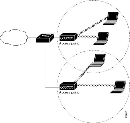
An access point connected directly to a wired LAN provides a connection point for wireless users. If more than one access point is connected to the LAN, users can roam from one area of a facility to another without losing their connection to the network. As users move out of range of one access point, they automatically connect to the network (associate) through another access point. The roaming process is seamless and transparent to the user. Figure 1-1 shows access points acting as root units on a wired LAN.
Figure 1-1 Access Points as Root Units on a Wired LAN

Repeater Access Point
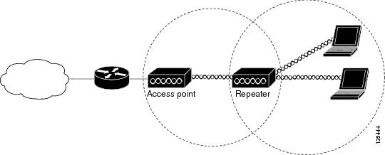
An access point can be configured as a stand-alone repeater to extend the range of your infrastructure or to overcome an obstacle that blocks radio communication. The repeater forwards traffic between wireless users and the wired LAN by sending packets to either another repeater or to an access point connected to the wired LAN. The data is sent through the route that provides the best performance for the client. Figure 1-2 shows an access point acting as a repeater. Consult the “Configuring a Repeater Access Point” for instructions on setting up an access point as a repeater.

Note![]() Non-Cisco client devices might have difficulty communicating with repeater access points.
Non-Cisco client devices might have difficulty communicating with repeater access points.
Figure 1-2 Access Point as Repeater

Bridges
Access points can be configured as root or non-root bridges. In this role, an access point establishes a wireless link with a non-root bridge. Traffic is passed over the link to the wired LAN. Access points in root and non-root bridge roles can be configured to accept associations from clients. Figure 1-3 shows an access point configured as a root bridge with clients. Figure 1-4 shows two access points configured as a root and non-root bridge, both accepting client associations. Consult the “Configuring the Role in Radio Network” section for instructions on setting up an access point as a bridge.
When wireless bridges are used in a point-to-multipoint configuration the throughput is reduced depending on the number of non-root bridges that associate with the root bridge. With a link data rate at 54 Mbps, the maximum throughput is about 25 Mbps in a point-to-point link. The addition of three bridges to form a point-to-multipoint network reduces the throughput to about 12.5 Mbps.
Figure 1-3 Access Point as a Root Bridge with Clients

Figure 1-4 Access Points as Root and Non-root Bridges with Clients

Workgroup Bridge
You can configure access points as workgroup bridges. In workgroup bridge mode, the unit associates to another access point as a client and provides a network connection for the devices connected to its Ethernet port. For example, if you need to provide wireless connectivity for a group of network printers, you can connect the printers to a hub or to a switch, connect the hub or switch to the access point Ethernet port, and configure the access point as a workgroup bridge. The workgroup bridge associates to an access point on your network.
If your access point has multiple radios, either radio can function in workgroup bridge mode..
Figure 1-5 shows an access point configured as a workgroup bridge. Consult the “Understanding Workgroup Bridge Mode” section and the “Configuring Workgroup Bridge Mode” section for information on configuring your access point as a workgroup bridge.
Figure 1-5 Access Point as a Workgroup Bridge

Central Unit in an All-Wireless Network
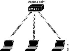
In an all-wireless network, an access point acts as a stand-alone root unit. The access point is not attached to a wired LAN; it functions as a hub linking all stations together. The access point serves as the focal point for communications, increasing the communication range of wireless users. Figure 1-6 shows an access point in an all-wireless network.
Figure 1-6 Access Point as Central Unit in All-Wireless Network

 Feedback