Cisco Aironet 14-dBi Vertically Polarized Sector Antenna (AIR-ANT2414S-R)
Available Languages
Table of Contents
Cisco Aironet 14-dBi Vertically Polarized Sector Antenna (AIR-ANT2414S-R)
Obtaining Documentation and Submitting a Service Request
Cisco Aironet 14-dBi Vertically Polarized Sector Antenna (AIR-ANT2414S-R)
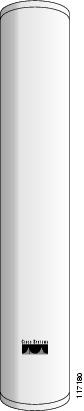
This describes the AIR-ANT2414S-R 14-dBi vertically polarized sector antenna, and provides specifications and mounting and aligning instructions. The antenna operates in the 2.4 GHz frequency range and is designed for use in bridging environments. The antenna is designed for outdoor use and can be mounted on 1.5 in. (3.8 cm) to 2.5 in. (6.3 cm) diameter masts.

System Requirements
This antenna is designed for use with Cisco Aironet access points and bridges but can be used with any 2.4 GHz Cisco Aironet radio device that utilizes an RP-TNC connector.

Note![]() Note: To meet regulatory restrictions, if you are using this antenna with a Cisco Aironet 1300 Series Wireless Bridge, the antenna must be professionally installed. The network administration or other IT professional responsible for installing and configuring the unit is a suitable professional installer. Following installation, access to the unit should be password protected by the network administrator to maintain regulatory compliance.
Note: To meet regulatory restrictions, if you are using this antenna with a Cisco Aironet 1300 Series Wireless Bridge, the antenna must be professionally installed. The network administration or other IT professional responsible for installing and configuring the unit is a suitable professional installer. Following installation, access to the unit should be password protected by the network administrator to maintain regulatory compliance.
Safety Precautions

Warning![]() This warning symbol means danger. You are in a situation that could cause bodily injury. Before you work on any equipment, be aware of the hazards involved with electrical circuitry and be familiar with standard practices for preventing accidents.
This warning symbol means danger. You are in a situation that could cause bodily injury. Before you work on any equipment, be aware of the hazards involved with electrical circuitry and be familiar with standard practices for preventing accidents.
Warning![]() Do not work on the system or connect or disconnect cables during periods of lightning activity.
Do not work on the system or connect or disconnect cables during periods of lightning activity.
Warning![]() This equipment must be grounded. Never defeat the ground conductor or operate the equipment in the absence of a suitably installed ground conductor. Contact the appropriate electrical inspection authority or an electrician if you are uncertain that suitable grounding is available.
This equipment must be grounded. Never defeat the ground conductor or operate the equipment in the absence of a suitably installed ground conductor. Contact the appropriate electrical inspection authority or an electrician if you are uncertain that suitable grounding is available.
Warning![]() Do not locate the antenna near overhead power lines or other electric light or power circuits, or where it can come into contact with such circuits. When installing the antenna, take extreme care not to come into contact with such circuits, as they may cause serious injury or death. For proper installation and grounding of the antenna, please refer to national and local codes (e.g. U.S.:NFPA 70, National Electrical Code, Article 810, in Canada: Canadian Electrical Code, Section 54).
Do not locate the antenna near overhead power lines or other electric light or power circuits, or where it can come into contact with such circuits. When installing the antenna, take extreme care not to come into contact with such circuits, as they may cause serious injury or death. For proper installation and grounding of the antenna, please refer to national and local codes (e.g. U.S.:NFPA 70, National Electrical Code, Article 810, in Canada: Canadian Electrical Code, Section 54).
Each year hundreds of people are killed or injured when attempting to install an antenna. In many of these cases, the victim was aware of the danger of electrocution, but did not take adequate steps to avoid the hazard.
For your safety and to help you achieve a good installation, please read and follow these safety precautions. They may save your life!
1.![]() If you are installing an antenna for the first time, for your own safety as well as others, seek professional assistance. Your Cisco sales representative can explain which mounting method to use for the size and type antenna you are about to install.
If you are installing an antenna for the first time, for your own safety as well as others, seek professional assistance. Your Cisco sales representative can explain which mounting method to use for the size and type antenna you are about to install.
2.![]() Select your installation site with safety, as well as performance in mind. Remember: electric power lines and phone lines look alike. For your safety, assume that any overhead line can kill you.
Select your installation site with safety, as well as performance in mind. Remember: electric power lines and phone lines look alike. For your safety, assume that any overhead line can kill you.
3.![]() Call your electric power company. Tell them your plans and ask them to come look at your proposed installation. This is a small inconvenience considering your life is at stake.
Call your electric power company. Tell them your plans and ask them to come look at your proposed installation. This is a small inconvenience considering your life is at stake.
4.![]() Plan your installation carefully and completely before you begin. Successful raising of a mast or tower is largely a matter of coordination. Each person should be assigned to a specific task, and should know what to do and when to do it. One person should be in charge of the operation to issue instructions and watch for signs of trouble.
Plan your installation carefully and completely before you begin. Successful raising of a mast or tower is largely a matter of coordination. Each person should be assigned to a specific task, and should know what to do and when to do it. One person should be in charge of the operation to issue instructions and watch for signs of trouble.
5.![]() When installing your antenna, remember:
When installing your antenna, remember:
b.![]() Do not work on a wet or windy day.
Do not work on a wet or windy day.
c.![]() Dress properly—shoes with rubber soles and heels, rubber gloves, long sleeved shirt or jacket.
Dress properly—shoes with rubber soles and heels, rubber gloves, long sleeved shirt or jacket.
6.![]() If the assembly starts to drop, get away from it and let it fall. Remember, the antenna, mast, cable, and metal guy wires are all excellent conductors of electrical current. Even the slightest touch of any of these parts to a power line complete an electrical path through the antenna and the installer: You!
If the assembly starts to drop, get away from it and let it fall. Remember, the antenna, mast, cable, and metal guy wires are all excellent conductors of electrical current. Even the slightest touch of any of these parts to a power line complete an electrical path through the antenna and the installer: You!
7.![]() If any part of the antenna system should come in contact with a power line, do not touch it or try to remove it yourself. Call your local power company. They will remove it safely.
If any part of the antenna system should come in contact with a power line, do not touch it or try to remove it yourself. Call your local power company. They will remove it safely.
8.![]() If an accident should occur with the power lines call for qualified emergency help immediately.
If an accident should occur with the power lines call for qualified emergency help immediately.
Installation Notes
The antenna is designed to be mounted on a mast but can be mounted on most flat vertical surfaces. If you mount the antenna on a vertical surface using the mounting hardware provided, you can adjust the antenna’s elevation but not its azimuth. Therefore, the surface on which you mount the antenna must be oriented in the direction of the bridge link.
Choosing a Mounting Location
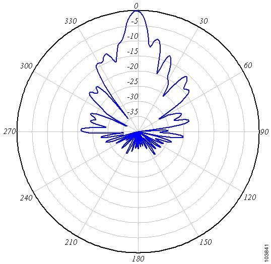
The antenna is designed to create a directional broadcast pattern. To achieve this pattern, mount the antenna clear of any obstructions to the sides of the radiating element. If the mounting location is on the side of a building or tower, the antenna pattern is degraded on the building or tower side.
Site Selection
Before attempting to install your antenna, determine where you can best place the antenna for safety and performance.
To determine a safe distance from wires, power lines, and trees:
1.![]() Measure the height of your antenna.
Measure the height of your antenna.
2.![]() Add this length to the length of your tower or mast and then double this total for the minimum recommended safe distance.
Add this length to the length of your tower or mast and then double this total for the minimum recommended safe distance.

Generally, the higher an antenna is above the ground, the better it performs. Good practice is to install your antenna about 5 to 10 ft (1.5 to 3 m) above the roof line and away from all power lines and obstructions. If possible, find a mounting place directly above your wireless device so that the lead-in cable can be as short as possible.
Hardware, Tools, and Fasteners Required
A mast mounting installation kit is shipped with the antenna and consists of the following hardware:
- Upper mounting bracket (adjustable)
- Lower mounting bracket (fixed)
- Mast mount clamps
- Four 4.0-in. (10.1 cm) ¼-20 hex head bolts with flat washers, split lock washers, and hex nuts
- Four ¾-in. (1.9 cm) ¼-20 hex head bolts with flat washers, split lock washers, and hex nuts
- Four ¼-20 hex nuts with split lock washers
You will need two 7/16-in. deep well sockets or wrenches to install the antenna. Mounting Bracket Assembly shows the mounting bracket assembly.
Installation Process
The following sections contain procedures for installing the antenna on a mast. Your installation may vary. The process consists of the following processes:
- Assembling the mounting brackets
- Attaching the mounting brackets to the antenna
- Mounting the antenna
- Aligning the antenna
- Grounding the antenna
Before you begin, refer to Mounting Bracket Assembly and Antenna Mounting Details to become familiar with the installation.
Assembling the Mounting Brackets
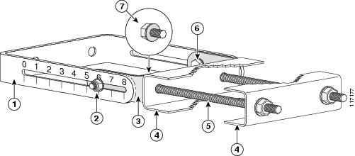
Two mounting brackets are provided; one is adjustable and the other is not. Mounting Bracket Assembly shows the adjustable bracket. The assembly process is the same for both brackets.
To assemble the mounting brackets:
1.![]() Position the mast mount clamp plate inside the antenna bracket.
Position the mast mount clamp plate inside the antenna bracket.
2.![]() Insert two ¼-20x ¾-in. hex head bolts into the holes in the mast mount clamp plate facing outward as shown in Mounting Bracket Assembly.
Insert two ¼-20x ¾-in. hex head bolts into the holes in the mast mount clamp plate facing outward as shown in Mounting Bracket Assembly.
3.![]() Place a flat washer and split lock washer on each hex head bolt.
Place a flat washer and split lock washer on each hex head bolt.
4.![]() Start a ¼-20 hex nut on each hex head bolt and tighten hand tight.
Start a ¼-20 hex nut on each hex head bolt and tighten hand tight.
5.![]() Place a flat washer on two 4-inch ¼-20 hex head bolts.
Place a flat washer on two 4-inch ¼-20 hex head bolts.
6.![]() Insert the bolts into the holes facing outward in the mast mount clamp plate.
Insert the bolts into the holes facing outward in the mast mount clamp plate.
7.![]() Install two mast mount clamps on the 4-inch ¼-20 hex head bolts as shown in Mounting Bracket Assembly.
Install two mast mount clamps on the 4-inch ¼-20 hex head bolts as shown in Mounting Bracket Assembly.
8.![]() Install a ¼-20 split lock washer and hex head nut on each bolt and tighten hand tight.
Install a ¼-20 split lock washer and hex head nut on each bolt and tighten hand tight.
9.![]() Go to Step 1 and assemble the second mounting bracket.
Go to Step 1 and assemble the second mounting bracket.
Figure 1 Mounting Bracket Assembly
Attaching the Mounting Brackets to the Antenna
The antenna has studs onto which you attach the installed mounting brackets to it. The adjustable bracket is installed on the top set of studs.
To attach the mounting brackets to the antenna:
1.![]() Position the antenna so that the arrow on the orientation label is pointed up. The arrow points to the top of the antenna so that it can be installed correctly.
Position the antenna so that the arrow on the orientation label is pointed up. The arrow points to the top of the antenna so that it can be installed correctly.
Note![]() The orientation label is located on the back panel of the antenna.
The orientation label is located on the back panel of the antenna.
2.![]() Attach the adjustable mounting bracket to the top set of mounting studs.
Attach the adjustable mounting bracket to the top set of mounting studs.
3.![]() Install two split lock washers and hex nuts on the studs. Use a 7/16-in. socket or wrench to tighten the nuts. Do not overtighten.
Install two split lock washers and hex nuts on the studs. Use a 7/16-in. socket or wrench to tighten the nuts. Do not overtighten.
4.![]() Attach the non-adjustable mounting bracket on the bottom set of mounting studs.
Attach the non-adjustable mounting bracket on the bottom set of mounting studs.
5.![]() Install two split lock washers and hex nuts on the studs and tighten as described in Step 3.
Install two split lock washers and hex nuts on the studs and tighten as described in Step 3.
6.![]() Use an appropriate socket or wrench to tighten the mounting bracket fasteners except the mast mount clamp fasteners.
Use an appropriate socket or wrench to tighten the mounting bracket fasteners except the mast mount clamp fasteners.
a.![]() Use a 7/16-in socket or wrench to capture the hex head bolt while you tighten the nuts.
Use a 7/16-in socket or wrench to capture the hex head bolt while you tighten the nuts.
b.![]() Do not complete tighten the nuts. Tighten them just enough so the bracket remains positioned but can be moved if necessary.
Do not complete tighten the nuts. Tighten them just enough so the bracket remains positioned but can be moved if necessary.
Mounting the Antenna
Antenna Mounting Details shows the side and rear view of a typical mast installation. Note that the adjustable bracket is in the top position. Depending on how your mast is configured, you may need to remove one of the mast mount clamps in order to mount the antenna.
Figure 2 Antenna Mounting Details

Note: Ensure that you follow all appropriate safety precautions for your installation.
To mount the antenna on the mast:
1.![]() Position the antenna on the mast so that the inside mast mount clamps are making good contact with the mast.
Position the antenna on the mast so that the inside mast mount clamps are making good contact with the mast.
2.![]() If you removed the outside mast mount clamp on the top bracket, reinstall it now. Ensure to retain the ¼-20 flat washers and split lock washers on the hex head bolts and start a ¼-20 hex nut on each bolt.
If you removed the outside mast mount clamp on the top bracket, reinstall it now. Ensure to retain the ¼-20 flat washers and split lock washers on the hex head bolts and start a ¼-20 hex nut on each bolt.
3.![]() Use a 7/16-in. deep well socket or wrench to tighten the nuts. Tighten the nuts enough so that the antenna will not slip down the mast (Mast Mount Clamp Detail).
Use a 7/16-in. deep well socket or wrench to tighten the nuts. Tighten the nuts enough so that the antenna will not slip down the mast (Mast Mount Clamp Detail).
Figure 3 Mast Mount Clamp Detail

4.![]() If you removed the outside mast mount clamp on the bottom bracket, reinstall it now. Ensure to retain the ¼-20 flat washers and split lock washers on the hex head bolts and start a ¼-20 hex nut on each bolt.
If you removed the outside mast mount clamp on the bottom bracket, reinstall it now. Ensure to retain the ¼-20 flat washers and split lock washers on the hex head bolts and start a ¼-20 hex nut on each bolt.
5.![]() Use a 7/16-in. deep well socket or wrench to tighten the nuts. Do not completely tighten the nuts.
Use a 7/16-in. deep well socket or wrench to tighten the nuts. Do not completely tighten the nuts.
6.![]() Rotate the antenna so that it points in the direction of the link you intend to establish.
Rotate the antenna so that it points in the direction of the link you intend to establish.
Aligning the Antenna
The antenna must be properly aligned if it is to be effective and efficient. If you are using this antenna with the Cisco Aironet 1300 Series Wireless Bridge, a detailed alignment procedure is contained in the Cisco Aironet 1300 Series Bridge Mounting Instructions, which is available on Cisco.com. The antenna must also be professionally installed if it is to be used with the 1300 series bridge.
Note: Polarization for the antennas you are aligning must be the same.
The goal when positioning a directional antenna is to align the local antenna for maximum received signal strength using the LED indications. The LEDs are convenient and easy to use. Normally, you observe a single large peak as you pan the antenna across the signal path. Think of the receive signal as a target (see Signal Strength Target).
Figure 4 Signal Strength Target

The target consists of concentric rings, with the strongest signal at the center and a progressively weaker signal at the outer rings. As you scan across the signal, you should observe the strong signal level when the antenna is properly aligned. If a vertical adjustment is required, look for the strong signal level as you tilt the antenna through its range.
Positioning the Antenna Using LED Indications
You can position the integrated antenna or a directional external antenna using the LEDs only after the bridge successfully associates with the remote bridge. In installation mode, the Install LED is continuous amber or green when the bridge has successfully associated. For the first 20 seconds following association, the bridge reads the received signal strength indication (RSSI) levels from the received packets and records the maximum value. After 20 seconds, the Ethernet, status, and radio LEDs on the bridge indicate relative RSSI readings (see Install Mode RSSI Display) compared to the maximum recorded during the initial 20 seconds.
When you are using LEDs to maximize the signal, adjust the antenna until as many LEDs as possible are on and the rest are blinking as fast as possible. With all three LEDS on, the signal is good enough to support the maximum data rate.
To position the antenna using the LED indicators:
1.![]() Verify that the Install LED is either continuous amber or green.
Verify that the Install LED is either continuous amber or green.
2.![]() Slowly pan the bridge to the left and right of the signal path, and watch for peaks in signal strength. Be sure to swing the antenna in an arc of 45 degrees to each side to ensure that the passes through the strongest signal level.
Slowly pan the bridge to the left and right of the signal path, and watch for peaks in signal strength. Be sure to swing the antenna in an arc of 45 degrees to each side to ensure that the passes through the strongest signal level.
3.![]() Return the bridge to the position where the signal is strongest.
Return the bridge to the position where the signal is strongest.
4.![]() Secure the horizontal adjustment by tightening the hex head bolts on the antenna bracket. Tighten the nuts wrench tight. Do not overtighten.
Secure the horizontal adjustment by tightening the hex head bolts on the antenna bracket. Tighten the nuts wrench tight. Do not overtighten.
5.![]() Slowly tilt the antenna, and watch for a peak in signal strength. Use the full vertical adjustment range of the mounting brackets.
Slowly tilt the antenna, and watch for a peak in signal strength. Use the full vertical adjustment range of the mounting brackets.
6.![]() Return the bridge to the position where the signal is strongest, normally where all signal strength LEDs are on. If you are unable to turn on all LEDs, simply maximize the signal.
Return the bridge to the position where the signal is strongest, normally where all signal strength LEDs are on. If you are unable to turn on all LEDs, simply maximize the signal.
7.![]() Secure the vertical adjustment by tightening the nuts that secure the adjustable antenna bracket to the mast mount clamp plate wrench tight. Do not overtighten.
Secure the vertical adjustment by tightening the nuts that secure the adjustable antenna bracket to the mast mount clamp plate wrench tight. Do not overtighten.
Grounding the Antenna
To ground the antenna in accordance with national electrical code instructions:
1.![]() Use No. 10 AWG copper or No. 8 or larger copper-clad steel or bronze wire as ground wires for both mast and lead-in. Securely clamp the wire to the bottom of the mast.
Use No. 10 AWG copper or No. 8 or larger copper-clad steel or bronze wire as ground wires for both mast and lead-in. Securely clamp the wire to the bottom of the mast.
2.![]() Secure the lead-in wire to an antenna discharge unit and the mast ground wire to the building with stand-off insulators spaced from 4 ft (1.2 m) to 8 ft (2.4 m) apart.
Secure the lead-in wire to an antenna discharge unit and the mast ground wire to the building with stand-off insulators spaced from 4 ft (1.2 m) to 8 ft (2.4 m) apart.
3.![]() Mount the antenna discharge unit as close as possible to where the lead-in wire enters the building.
Mount the antenna discharge unit as close as possible to where the lead-in wire enters the building.
4.![]() Drill a hole in the building’s wall as close as possible to the equipment to which you will connect the lead-in cable.
Drill a hole in the building’s wall as close as possible to the equipment to which you will connect the lead-in cable.
5.![]() Pull the cable through the hole and form a drip loop close to where it enters the building.
Pull the cable through the hole and form a drip loop close to where it enters the building.
6.![]() Thoroughly waterproof the lead-in area.
Thoroughly waterproof the lead-in area.
Suggested Cable
Cisco recommends a high-quality, low-loss cable for use with the antenna.
Note![]() Coaxial cable loses efficiency as the frequency increases, resulting in signal loss. The cable should be kept as short as possible because cable length also determines the amount of signal loss (the longer the run, the greater the loss).
Coaxial cable loses efficiency as the frequency increases, resulting in signal loss. The cable should be kept as short as possible because cable length also determines the amount of signal loss (the longer the run, the greater the loss).
The antenna terminates with a RP-TNC plug after a short, 5-ft (1.5-m) cable. The mating connector to the antenna is an appropriate RP-TNC jack. The connector on the opposite end will vary according to the type of equipment used.
After the cable is attached to the antenna, make sure that the connections are sealed (if outdoors) to prevent moisture and other weathering elements from affecting performance. Cisco recommends using a coax seal (such as CoaxSeal) for outdoor connections. Silicon sealant or electrical tape are not recommended for sealing outdoor connections.
Obtaining Documentation and Submitting a Service Request
For information on obtaining documentation, using the Cisco Bug Search Tool (BST), submitting a service request, and gathering additional information, see What’s New in Cisco Product Documentation at: http://www.cisco.com/c/en/us/td/docs/general/whatsnew/whatsnew.html.
Subscribe to What’s New in Cisco Product Documentation, which lists all new and revised Cisco technical documentation as an RSS feed and delivers content directly to your desktop using a reader application. The RSS feeds are a free service.
THE SPECIFICATIONS AND INFORMATION REGARDING THE PRODUCTS IN THIS MANUAL ARE SUBJECT TO CHANGE WITHOUT NOTICE. ALL STATEMENTS, INFORMATION, AND RECOMMENDATIONS IN THIS MANUAL ARE BELIEVED TO BE ACCURATE BUT ARE PRESENTED WITHOUT WARRANTY OF ANY KIND, EXPRESS OR IMPLIED. USERS MUST TAKE FULL RESPONSIBILITY FOR THEIR APPLICATION OF ANY PRODUCTS.
THE SOFTWARE LICENSE AND LIMITED WARRANTY FOR THE ACCOMPANYING PRODUCT ARE SET FORTH IN THE INFORMATION PACKET THAT SHIPPED WITH THE PRODUCT AND ARE INCORPORATED HEREIN BY THIS REFERENCE. IF YOU ARE UNABLE TO LOCATE THE SOFTWARE LICENSE OR LIMITED WARRANTY, CONTACT YOUR CISCO REPRESENTATIVE FOR A COPY.
The following information is for FCC compliance of Class A devices: This equipment has been tested and found to comply with the limits for a Class A digital device, pursuant to part 15 of the FCC rules. These limits are designed to provide reasonable protection against harmful interference when the equipment is operated in a commercial environment. This equipment generates, uses, and can radiate radio-frequency energy and, if not installed and used in accordance with the instruction manual, may cause harmful interference to radio communications. Operation of this equipment in a residential area is likely to cause harmful interference, in which case users will be required to correct the interference at their own expense.
The following information is for FCC compliance of Class B devices: This equipment has been tested and found to comply with the limits for a Class B digital device, pursuant to part 15 of the FCC rules. These limits are designed to provide reasonable protection against harmful interference in a residential installation. This equipment generates, uses and can radiate radio frequency energy and, if not installed and used in accordance with the instructions, may cause harmful interference to radio communications. However, there is no guarantee that interference will not occur in a particular installation. If the equipment causes interference to radio or television reception, which can be determined by turning the equipment off and on, users are encouraged to try to correct the interference by using one or more of the following measures:
- Reorient or relocate the receiving antenna.
- Increase the separation between the equipment and receiver.
- Connect the equipment into an outlet on a circuit different from that to which the receiver is connected.
- Consult the dealer or an experienced radio/TV technician for help.
Modifications to this product not authorized by Cisco could void the FCC approval and negate your authority to operate the product.
The Cisco implementation of TCP header compression is an adaptation of a program developed by the University of California, Berkeley (UCB) as part of UCB’s public domain version of the UNIX operating system. All rights reserved. Copyright © 1981, Regents of the University of California.
NOTWITHSTANDING ANY OTHER WARRANTY HEREIN, ALL DOCUMENT FILES AND SOFTWARE OF THESE SUPPLIERS ARE PROVIDED “AS IS” WITH ALL FAULTS. CISCO AND THE ABOVE-NAMED SUPPLIERS DISCLAIM ALL WARRANTIES, EXPRESSED OR IMPLIED, INCLUDING, WITHOUT LIMITATION, THOSE OF MERCHANTABILITY, FITNESS FOR A PARTICULAR PURPOSE AND NONINFRINGEMENT OR ARISING FROM A COURSE OF DEALING, USAGE, OR TRADE PRACTICE.
IN NO EVENT SHALL CISCO OR ITS SUPPLIERS BE LIABLE FOR ANY INDIRECT, SPECIAL, CONSEQUENTIAL, OR INCIDENTAL DAMAGES, INCLUDING, WITHOUT LIMITATION, LOST PROFITS OR LOSS OR DAMAGE TO DATA ARISING OUT OF THE USE OR INABILITY TO USE THIS MANUAL, EVEN IF CISCO OR ITS SUPPLIERS HAVE BEEN ADVISED OF THE POSSIBILITY OF SUCH DAMAGES.
Any Internet Protocol (IP) addresses and phone numbers used in this document are not intended to be actual addresses and phone numbers. Any examples, command display output, network topology diagrams, and other figures included in the document are shown for illustrative purposes only. Any use of actual IP addresses or phone numbers in illustrative content is unintentional and coincidental.
All printed copies and duplicate soft copies are considered un-Controlled copies and the original on-line version should be referred to for latest version.
Cisco has more than 200 offices worldwide. Addresses, phone numbers, and fax numbers are listed on the Cisco website at www.cisco.com/go/offices.
 Feedback
Contact Cisco
- Open a Support Case

- (Requires a Cisco Service Contract)